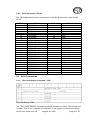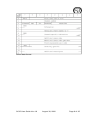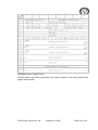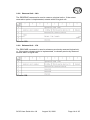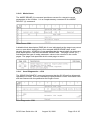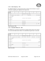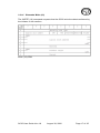
1
SC35 Mastodon 3.5” Solid State SCSI Drive User Guide 153205-001 Revision 4.8 July 30, 2002 Memtech SSD Corporation 7628 Las Positas Road Livermore, CA 94550 (800)445-5511 www.memtech.com Table Of Contents 1. HIGHLIGHTS 3 2. INTRODUCTION 3 GENERAL DESCRIPTION 4 3. 3.1 3.2 4. 5. 19 INSTALLATION 20 20 20 21 21 22 Switch Locations SCSI ID Selection Write Protection Termination Jumper Definitions Memory Size 22 23 23 23 23 23 TROUBLE SHOOTING GUIDE 7.1 7.2 7.3 7.4 8. Default Configuration Hardware Installation Procedure Power and Cable Attachments Software Installation Procedure JUMPER CONFIGURATION 6.1 6.2 6.3 6.4 6.5 6.6 7. 4 5 GENERAL SPECIFICATIONS 5.1 5.2 5.3 5.4 6. SCSI Interface SCSI Commands APPENDIX 8.1 8.2 8.3 24 Error Blink Codes Warning Blink Codes – Red LED on steady at power-upUnit does not respond to SCSI commands - 25 Contact Information SCSI specification information Limited Lifetime Warranty SC35 User Guide Ver 4.8 24 24 24 24 August 30, 2002 25 25 25 Page 2 of 25 1. HIGHLIGHTS • • • • • • • • • • • • • • • • 27648 Mbyte uncompressed capacity Full -40oC to +85oC operating temp range Active Remap™ Wear Leveling Technology Unmatched SCSI-II compatibility On-board active termination 5 volt, low power operation Completely solid state - no moving parts 500G operating shock 10G operating vibration Rugged, 3.5” half height drive formfactor Single-ended 50 pin SCSI interface 0.7 millisecond random access time 1.5 Mbyte/sec sustained Read throughput 650 Kbyte/sec sustained Write throughput 10 year guaranteed data integrity NO installable device drivers 2. INTRODUCTION The SC35 series is a line of 100% compatible SCSI-II solid state drives in a 3.5-inch half-height format. It is completely solid state, with no moving parts. This accounts for the unit’s exceptional ruggedness and wide operating temperature range. Sector Erasable NAND E2PROM (Flash) in 128 Mbit to 1 Gbit configurations are used to provide up to 27648 Mbytes of nonvolatile, solid state storage in an extremely small, rugged form factor. The drive is 100% SCSI compatible and requires no special drivers to operate. It is essentially a drop in replacement for standard rotating media. The SC35 can be used in applications where operating conditions are harsh and when reliability is critical. A 100% CMOS logic design minimizes power consumption, and the +5 volt only power requirement simplifies system supply needs, as +12 volts is not necessary. An on-board microprocessor implements all control functions, and oversees SCSI communications via a 53C90A SCSI-II processor. The microprocessor performs all power up diagnostics, data transfers, and error handling in the unit. The SC35 can sustain a 1.5 Mbyte per second read throughput and 650 Kbyte per second write throughput. The unit responds to all Direct-Access device commands, and as with all single-ended SCSI units, the SC35 may be placed up to 18 feet (6 m) from the host SCSI controller. Data integrity is maintained using Memtech’s proprietary Active Remap™ technology. The drive is available in capacities ranging from 128 Mbytes to 27648 Mbytes. Please contact the factory with your requirements. Disk compression utilities may be used to effectively double the usable capacity of the drive. Every drive is fully tested under environmental extremes, which guarantees data integrity under even the harshest conditions. SC35 User Guide Ver 4.8 August 30, 2002 Page 3 of 25 3. GENERAL DESCRIPTION 3.1 SCSI Interface An intelligent SCSI controller from NCR, the 53C90A, handles the SCSI interface for the SC35. The 53C90A is SCSI-I and SCSI II compliant, and automates much of the interface overhead. It has a 16 byte FIFO, a DMA interface, and numerous command and control registers. The SC35 employs the following attributes: 1. 2. 3. 4. 5. Single-ended drivers Termination power derived from cable Parity on the interface "Hard" RESET implemented No reservation queuing The SC35 has implemented all mandatory SCSI-I and SCSI- II commands and several optional commands to enhance functionality. The following is a list of commands and their equivalent hexadecimal representation. 1. 2. 3. 4. 5. 6. 7. 8. 9. 10. 11. 12. 13. 14. 15. 16. Test Unit Ready Rezero Unit Request Sense Format Unit Read Write Inquiry Reserve Unit Release Unit Mode Sense Send Diagnostics Read Capacity Extended Read Extended Write Erase Verify 00h 01h 03h 04h 08h 0Ah 12h 16h 17h 1Ah 1Dh 25h 28h 2Ah 2Ch 2Fh M O M M M O M M M O M M M O O O Notes: O = Optional M = Mandatory The implemented messages on the SC35 are as follows: 1. 2. 3. 4. 5. 6. 7. 8. 9. Command Complete Extended Message Init Detected Error Abort Message Reject NoOp Message Message Parity Error Bus Device Reset Identify SC35 User Guide Ver 4.8 00h 01h 05h 06h 07h 08h 09h 0Ch 80h August 30, 2002 Generated Both Received Received Generated Received Received Received Received Page 4 of 25 3.2 SCSI Connector The SC35 uses a 50-pin right angle 0.1 inch center connector mounted on the PCB to create both a power and signal connection to the host. Maximum cable length is 6 meters. The diagram below depicts connector orientation and location. 3.2.1 SCSI Connector Physical Orientation Pin #1 SC35 User Guide Ver 4.8 August 30, 2002 Page 5 of 25 3.2.2 SCSi Connector Pinout The following shows the pin connections for the SCSI connector used on the SC35. PIN 1 3 5 7 9 11 13 15 17 19 21 23 25 27 29 31 33 35 37 39 41 43 45 47 49 SIGNAL GROUND GROUND GROUND GROUND GROUND GROUND GROUND GROUND GROUND GROUND GROUND RSVD GROUND RSVD GROUND GROUND GROUND GROUND GROUND GROUND GROUND GROUND GROUND GROUND GROUND PIN 2 4 6 8 10 12 14 16 18 20 22 24 26 28 30 32 34 36 38 40 42 44 46 48 50 SIGNAL DB0 DB1 DB2 DB3 DB4 DB5 DB6 DB7 DBP GROUND GROUND RSVD TERMPWR RSVD GROUND ATN GROUND BSY ACK RST MSG SEL C/D REQ I/O 3.3 SCSI Commands 3.3.1 Test Unit Ready Command – 00h Test Unit Ready CDB The TEST UNIT READY command provides a means to check if the logical unit is ready. This is not a request for a self-test. If the logical unit would accept an SC35 User Guide Ver 4.8 August 30, 2002 Page 6 of 25 appropriate medium-access command without returning CHECK CONDITION status, this command shall return a GOOD status. If the logical unit cannot become operational or is in a state such that an initiator action is required to make the unit ready, the target shall return CHECK CONDITION status with a sense key of NOT READY. 3.3.2 Rezero Unit Command – 01h Rezero Unit CDB The REZERO UNIT command requests that the target set the logical unit to a specific state. This is implemented on the SC35 as a NOP command and has no effect other than to verify the CDB. SC35 User Guide Ver 4.8 August 30, 2002 Page 7 of 25 3.3.3 Request Sense Command – 03h Request Sense CDB The REQUEST SENSE command requests that the SC35 transfer sense data to the initiator. If the SC35 has no sense data available to return, it will return a sense key of NO SENSE and an additional sense code of NO ADDITIONAL SENSE INFORMATION. The sense data shall be preserved by the target for the initiator until retrieved by a REQUEST SENSE command or until the receipt of any other I/O process for the same I_T_x nexus. Sense data shall be cleared upon receipt of any subsequent I/O process (including REQUEST SENSE) to the same I_T_x nexus. The target shall return CHECK CONDITION status for a REQUEST SENSE command only to report exception conditions specific to the command itself. For example: a) A non-zero reserved bit is detected in the command descriptor block; b) An unrecovered parity error is detected on the data bus; c) A target malfunction prevents return of the sense data. If a recovered error occurs during the execution of the REQUEST SENSE command, the target shall return the sense data with GOOD status. If a target returns CHECK CONDITION status for a REQUEST SENSE command, the sense data may be invalid. The SC35 is capable of returning eighteen bytes of data in response to a REQUEST SENSE command. If the allocation length is eighteen or greater, and the SC35 returns less than eighteen bytes of data, the initiator should assume that the bytes not transferred would have been zeros had the target returned those bytes. Initiators can determine how much sense data was returned by examining the allocation length parameter in the command descriptor block and the additional sense length in the sense data. The sense data format for error codes 70h (current errors) and 71h (deferred errors) are defined below. For further details on the Request Sense command, please refer to the SCSI specification. SC35 User Guide Ver 4.8 August 30, 2002 Page 8 of 25 Sense data format SC35 User Guide Ver 4.8 August 30, 2002 Page 9 of 25 3.3.4 Format Unit Command – 04h The FORMAT UNIT command formats the medium into initiator addressable logical blocks per the initiator-defined options. In addition, the medium may be certified and control structures may be created for the management of the medium and defects. Format Unit CDB Only the simplest and mandatory forms of the FORMAT UNIT command (with no format data) are implemented on the SC35. This routine accomplishes medium formatting with little initiator control over defect management. The FORMAT UNIT command shall be rejected with RESERVATION CONFLICT status if the logical unit is reserved, or any extent reservation, from any initiator, is active in the specified logical unit. During the execution of the FORMAT UNIT command, the SC35 may perform a medium defect management algorithm. A FmtData bit of zero indicates that a DATA OUT phase shall not occur. The source of defect information is not specified. This is the only form of the command the SC35 supports. A complete list (CmpLst) bit of one indicates that the defect list sent by the initiator is a complete list of defects. The existing defect list is discarded by the SC35 and a new primary defect list is constructed. A CmpLst bit of zero indicates that the current defect list should be maintained. As a result a new primary is constructed that contains the existing list and any new defects the SC35 may add during the format operation. SC35 User Guide Ver 4.8 August 30, 2002 Page 10 of 25 3.3.5 Read (6) Command – 08h The READ (6) command requests that the SC35 transfer data to the initiator. The most recent data value written in the addressed logical block shall be returned. Read (6) CDB The logical block address field specifies the logical block at which the read operation shall begin. The transfer length field specifies the number of contiguous logical blocks of data to be transferred. A transfer length of zero indicates that 256 logical blocks shall be transferred. Any other value indicates the number of logical blocks that shall be transferred. 3.3.6 Write (6) Command – 0Ah The WRITE (6) command requests that the target write the data transferred by the initiator to the medium. Write (6) CDB The logical block address field specifies the logical block at which the write operation shall begin. The transfer length field specifies the number of contiguous logical blocks of data to transfer. A transfer length of zero indicates that 256 logical blocks shall be transferred. Any other value indicates the number of logical blocks that shall be transferred. SC35 User Guide Ver 4.8 August 30, 2002 Page 11 of 25 3.3.7 Inquiry Command – 12h The INQUIRY command requests that information regarding parameters of the SC35 be sent to the initiator. Inquiry CDB An enable vital product data (EVPD) bit of one specifies that the SC35 return the optional vital product data specified by the page code field. If any optional fields in the CDB are set that the SC35 does not support, it will return a CHECK CONDITION status with the sense key set to ILLEGAL REQUEST and an additional sense code of INVALID FIELD IN CDB. An EVPD bit of zero specifies that the SC35 return the standard INQUIRY data. If the page code field is not zero, the target shall return CHECK CONDITION status with the sense key set to ILLEGAL REQUEST and an additional sense code of INVALID FIELD IN CDB. The page code field specifies which page of vital product data information the SC35 return. The INQUIRY command shall return CHECK CONDITION status only when the target cannot return the requested INQUIRY data. The INQUIRY data should be returned even though the peripheral device may not be ready for other commands. If an INQUIRY command is received from an initiator with a pending unit attention condition, the SC35 will perform the INQUIRY command and not clear the unit attention condition. SC35 User Guide Ver 4.8 August 30, 2002 Page 12 of 25 Standard Inquiry Data Format Please refer to the SCSI specification for further details on the vital product data pages and formats. SC35 User Guide Ver 4.8 August 30, 2002 Page 13 of 25 3.3.8 Reserve Unit – 16h The RESERVE command is used to reserve a logical unit or, if the extent reservation option is implemented, extents within a logical unit. Reserve CDB 3.3.9 Release Unit – 17h The RELEASE command is used to release a previously reserved logical unit, or, if the extent release option is implemented, to release previously reserved extents within a logical unit. Release CDB SC35 User Guide Ver 4.8 August 30, 2002 Page 14 of 25 3.3.10 Mode Sense The MODE SENSE (6) command provides a means for a target to report parameters to the initiator. It is a complementary command to the MODE SELECT (6) command. Mode Sense CDB A disable block descriptors (DBD) bit of zero indicates that the target may return zero or more block descriptors in the returned MODE SENSE data, at the target’s discretion. A DBD bit of one specifies that the target shall not return any block descriptors in the returned MODE SENSE data. The page control (PC) field defines the type of mode parameter values to be returned in the mode pages. The page code specifies which mode page to return. 3.3.11 Send Diagnostics – 1Dh The SEND DIAGNOSTIC command requests that the SC35 perform diagnostic operations on itself. The only mandatory implementation of this command is the self-test feature with the parameter list length of zero. Send Diagnostics CDB SC35 User Guide Ver 4.8 August 30, 2002 Page 15 of 25 3.3.12 Read Capacity – 25h The READ CAPACITY command provides a means for the initiator to request information regarding the capacity of the logical unit. Read Capacity CDB 3.3.13 Extended Read (10) – 28h The READ (10) command requests that the target transfer data to the initiator. The most recent data value written in the addressed logical block is returned. Read (10) CDB SC35 User Guide Ver 4.8 August 30, 2002 Page 16 of 25 3.3.14 Extended Write (10) The WRITE (10) command requests that the SC35 write the data transferred by the initiator to the medium. Write (10) CDB SC35 User Guide Ver 4.8 August 30, 2002 Page 17 of 25 3.3.15 Erase Command Erase CDB The ERASE (10) command requests that the target erase the specified number of blocks starting at the specified logical block address on the medium. As used here, erased means the medium shall be erased. The previous data recorded on the medium, if any, shall not be recoverable. The Remap Table is retained, thus allowing write and read access to the memory. The erase all (ERA) bit set to one indicates that all blocks on the medium shall be erased. If the ERA bit is set to one and if the number of blocks is not zero, the SC35 will return CHECK CONDITION, and the sense key shall be set to ILLEGAL REQUEST, with an additional sense code of INVALID FIELD IN CDB. If the ERA bit is zero a transfer length of zero indicates that no blocks shall be erased. This condition is not considered an error and no data is erased. Any other value indicates the number of logical blocks that shall be erased. A note about the Erase Command – The erase command has been implemented as a security erase mechanism on the SC35. When executed with ERA set, a 768 Mbyte drive can be wiped clean in under 10 seconds. All storage locations on the drive are erased, including both user and system (protected) data areas. At the conclusion of the erase command, the existing Remap Table™ is restored to memory. If you wish to wipe the Remap Table™ information as well, please contact the factory for implementation instructions. SC35 User Guide Ver 4.8 August 30, 2002 Page 18 of 25 4. GENERAL SPECIFICATIONS Interface SCSI Compatibility SCSI Device Type Maximum Capacity Bytes/Block Bus Width Termination ANSI X3.131-1994 0 - Direct Access Device 27648 Mbytes 512 8 bits Active – on board Data Transfer Specifications Bus width Read Transfer Rate Write Transfer Rate Data Access time 1 byte (8 bits) 1.5 Mbyte/sec., sustained 650 Kbytes/sec sustained 0.7 msec Environmental Requirements Operating Ambient Temperature Commercial Extended Industrial Storage Temperature Humidity Airflow Requirements Ceiling 0oC to +70oC -20oC to +75oC -40 oC to +85 oC -55oC to +125oC Ambient 5% to 95% non-condensing none no limit Mechanical (Full Capacity) Length Width Max Height Drive Form Factor Mounting Considerations Max Weight 15.24cm (6.00 in.) 10.16cm (4.00 in.) 03.68cm (1.45 in.) 3.5" half height drive None (any orientation) 18.5 ounces (525 grams) Power Requirements Vcc Supply Vdd Supply Power Idle Power Active Power Max +5.00 volts +/- 5% Not Used 0.50 watts 0.90 watts 1.10 watts SC35 User Guide Ver 4.8 August 30, 2002 Page 19 of 25 5. INSTALLATION 5.1 Default Configuration The default jumper switch configuration is given below. Always power down the unit before changing the SCSI ID or write protect switches. Changing these settings with power applied may result in the changes not being recognized. New with this revision is the addition of a jumper block on the front of the drive. Please refer to the diagram below for the location of the block. Settings can be made from either the switch located near the power connector, or the jumper block. Setting either a switch on or placing a jumper on a block will result in that setting being enabled. See definitions below. DEFAULT JUMPER SWITCH CONFIGURATION a. SCSI ID: Device 0 ID0 - ON Switch pos. 1 on ID1 - ON Switch pos. 2 on ID2 - ON Switch pos. 3 on b. Writes: Enabled WP* - OFF Switch pos. 4 off c. Termination: Disabled E1 on E2 on E3 on E4 off E5 off 5.2 Hardware Installation Procedure 5.2.1 Verify that the drive is configured as required by the application. Many SCSI controllers require that the system disk be addressed as device 0 or 1 on the SCSI bus. If a different ID is required, refer to section 6 for proper switch settings. 5.2.2 Power off the computer system by throwing the main power switch. 5.2.3 Disconnect the AC power cord from the computer system. 5.2.4 Open the system to allow access to the drive bays and the card slots as required. 5.2.5 If a SCSI initiator is not already installed in the system or on the motherboard, then install that card. 5.2.6 Install the SC35 into a standard 3 1/2" drive bay, or using adapter hardware, place the unit into a 5 1/4" drive bay. Any mounting orientation is acceptable. 5.2.7 Attach the 50-pin flat ribbon connector from the SCSI initiator to the SC35. If multiple devices are to be attached to the SCSI bus, then remove any terminating resistors or disable active termination on those units not at the END of the cable. Only the two devices at the ends of the SCSI bus should have termination enabled. Failure to comply with this requirement may cause erroneous operation of the SCSI bus. SC35 User Guide Ver 4.8 August 30, 2002 Page 20 of 25 5.2.8 Make sure that pin one on the cable, on the SCSI controller and on the SC35 are correctly aligned. The SC35 uses a square pad on the connector to indicate pin one, and most cables are marked with a triangle on the connector or a stripe on the cable itself to indicate the first pin. 5.2.9 Attach the power cable from the system power supply to the SC35. This cable is keyed and cannot be inserted backwards. At this point, installation is complete. 5.2.10 Reattach the AC power cable to the system and power-up. 5.3 Power and Cable Attachments The following diagram depicts the SC35 as viewed from the connector (Back View). Pin 1 of the SCSI interface and the power connections are as labeled. Pin #1 V C C G G V N N D D D D VCC = +5.00 volts +/- 5% GND = 0 volts VDD = +12.00 volts (or no connection) Figure 1: Back view of SC35 5.4 Software Installation Procedure With the SC35 installed, the user can now treat the device as a standard Direct Access SCSI device. Standard implementation of the SC35 will include building a partition table with FDISK and high-level formatting. Low level formatting is not required, nor recommended. Refer to your system documentation for detailed instructions. SC35 User Guide Ver 4.8 August 30, 2002 Page 21 of 25 6. JUMPER CONFIGURATION 6.1 Switch Locations The following diagram shows the unit as viewed from the bottom, and shows the relative location of the switches and jumpers as described in the text below. E1 E2 E3 E4 E5 ERR WP ID2 ID1 ID0 ACT Figure 2: Bottom view of SC35 SC35 User Guide Ver 4.8 August 30, 2002 Page 22 of 25 6.2 SCSI ID Selection 6.2.1 The SC35 can use any of the 8 SCSI IDs available on the SCSI bus, although the highest priority device, SCSI ID 7, is usually reserved for the initiator. Switch selection for each SCSI ID is shown below. For a setting to be off, BOTH the switch and jumper must be off. ID2 or E3 ON ON ON ON OFF OFF OFF OFF ID1 or E2 ON ON OFF OFF ON ON OFF OFF ID0 or E1 ON OFF ON OFF ON OFF ON OFF SCSI ID SELECTED SCSI ID 0 SCSI ID 1 SCSI ID 2 SCSI ID 3 SCSI ID 4 SCSI ID 5 SCSI ID 6 SCSI ID 7 6.3 Write Protection The WP switch of jumper is used to write protect the SC35. When the host processor sends a write command, the condition of this switch is checked. If the switch is on writes are disabled, and an error message will be returned to the SCSI controller. Moving the switch to the off position will enable writes on the board, allowing full read/write access to the memory array. 6.4 Termination Unlike previous versions of the SC35, Memtech now employs active termination on SCSI drives. Termination is normally disabled on the drive. To enable termination, install the jumper located at E5. 6.5 Jumper Definitions Jumpers E6, E7 and E8 are used during initial testing at the factory and should NOT be installed under normal operating conditions. 6.6 Memory Size Memory size is determined when the SC35 is built and preformatted at the factory. With some SCSI adapter cards the memory size is displayed when the BIOS message is returned at power up. If that memory size changes, contact Memtech factory repair. Memory capacity can only be upgraded at the factory. SC35 User Guide Ver 4.8 August 30, 2002 Page 23 of 25 7. TROUBLE SHOOTING GUIDE The following is a list of possible error indicators or messages, what they indicate, and possible solutions to the source problem. If no solution is found, contact the factory for further assistance. 7.1 Error Blink Codes If the red LED issues a repeating blink code (accompanied by the drive not responding to SCSI commands), this indicates a hard error condition as listed in the table below. Contact the Memtech factory for repair service. Number of Blinks 2 3 4 5 6 7 Error ROM Firmware Checksum error ASIC initialization error SRAM Test failed Remap Table error SCSI controller error Flash/Data Path error 7.2 Warning Blink Codes – The red LED is also used to indicate a number of warning conditions. If a warning condition is encountered, the red LED will issue the number of blinks indicated below a single time, then continue the power-up procedure. Please note that the warning condition is also entered after each SCSI reset, so the blink code may be issued several times during power-up at irregular intervals. Again, contact the Memtech factory for service or repair. Number of Blinks 1 2 3 Error No Flash memory Invalid Remap Table Remap Table disabled (E7 shorted) 7.3 Red LED on steady at power-upThe red LED will come on when the remap table becomes full. One or more memory devices have exceeded their useful life. Contact Memtech repair department for repair or upgrade options. 7.4 Unit does not respond to SCSI commands If the unit passes power-up diagnostics, but does not respond to SCSI commands, there may be a SCSI ID contention among the SCSI bus units. Make sure that every SCSI ID used on the bus is different. See section 5 to find out how to change the SCSI ID of the unit. Note: Status and Sense Error Codes are available in the Reference Manual. SC35 User Guide Ver 4.8 August 30, 2002 Page 24 of 25 8. Appendix 8.1 Contact Information For Technical Support or Warranty Repair information, please contact Memtech at: 7628 Las Positas Road Livermore, CA 94550 U.S.A. Phone: (925) 294-8483 Fax: (925) 294-5920 Email: [email protected] 8.2 SCSI specification information Information regarding the SCSI-II specification may be obtained from the following locations: Global Engineering 15 Inverness Way East Englewood, Co. 80112-5704 Phone: (303) 792-2181 or (800) 854-7179 Fax: (303) 792-2192 8.3 Limited Lifetime Warranty Memtech SSD Corporation (Memtech) warrants your SC35 against defects in material and workmanship for the life of the drive. The warranty is void in the case of misuse, accident, alteration, improper installation, misapplication or the result of unauthorized service or repair. The implied warranties of merchantability and fitness for a particular purpose, and all other warranties, expressed or implied, except as set forth in this warranty, shall not apply to the products delivered. In no event shall Memtech be liable for any lost profits, lost savings or other incidental or consequential damages arising out of the use of, or inability to use, this product. BEFORE RETURNING PRODUCT, A RETURN MATERIAL AUTHORIZATION (RMA) MUST BE OBTAINED FROM MEMTECH. Product shall be returned to Memtech with shipping prepaid. If the product fails to conform and warranty repair is necessary, Memtech will reimburse customer for the transportation charges incurred. SC35 User Guide Ver 4.8 August 30, 2002 Page 25 of 25