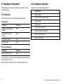
1
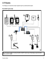
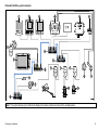
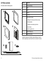
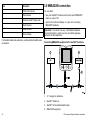
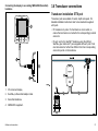
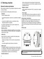
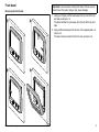
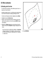
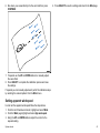
i7 0 In s t r u m e n t
d is p la y
Ins ta lla tion ins tructions
ENGLIS H
Docume nt numbe r: 87131-1
Da te : 11-2010
Trademark and patents notice
Autohelm, hsb2, RayTech Navigator, Sail Pilot, SeaTalk, SeaTalkNG, SeaTalkHS and Sportpilot are registered trademarks of Raymarine
UK Limited. RayTalk, Seahawk, Smartpilot, Pathfinder and Raymarine are registered trademarks of Raymarine Holdings Limited.
FLIR is a registered trademark of FLIR Systems, Inc. and/or its subsidiaries.
All other trademarks, trade names, or company names referenced herein are used for identification only and are the property of
their respective owners.
This product is protected by patents, design patents, patents pending, or design patents pending.
Fair Use Statement
You may print no more than three copies of this manual for your own use. You may not make any further copies or distribute or use the
manual in any other way including without limitation exploiting the manual commercially or giving or selling copies to third parties.
Copyright ©2011 Raymarine UK Ltd. All rights reserved.
ENGLISH
Document number: 87131-1
Date: 11-2010
Contents
Chapter 1 Important information............................. 7
3.3 SeaTalkng connections............................................... 24
TFT LCD Displays .......................................................... 7
3.4 SeaTalk connection ................................................... 25
Water ingress ................................................................. 7
Disclaimers .................................................................... 8
3.5 NMEA2000 connection .............................................. 26
EMC installation guidelines ............................................. 8
Suppression ferrites ........................................................ 8
Connections to other equipment ...................................... 9
Declaration of conformity................................................. 9
Product disposal ............................................................. 9
Warranty registration....................................................... 9
IMO and SOLAS............................................................. 9
Technical accuracy ......................................................... 9
Chapter 2 Planning the installation ........................ 11
2.1 Handbook information ............................................... 12
2.2 Installation checklist .................................................. 12
2.3 i70 Systems.............................................................. 13
2.4 System protocols ...................................................... 17
3.6 Transducer connections ............................................ 27
Chapter 4 Location and mounting .......................... 29
4.1 Selecting a location ................................................... 30
4.2 Mounting .................................................................. 31
Chapter 5 System checks ........................................ 35
5.1 Initial power on test ................................................... 36
5.2 Using the setup wizard .............................................. 37
5.3 Transducer calibration ............................................... 37
5.4 Depth calibration ....................................................... 38
5.5 Speed calibration ...................................................... 39
5.6 Wind calibration ........................................................ 42
5.7 Trim tab display calibration ........................................ 44
5.8 Setup menu .............................................................. 44
2.5 Pack contents ........................................................... 18
Chapter 6 Troubleshooting...................................... 59
2.6 Tools ........................................................................ 19
6.1 Troubleshooting ........................................................ 60
Chapter 3 Cables and connections......................... 21
3.1 General cabling guidance .......................................... 22
3.2 Connections overview ............................................... 23
6.2 Power up troubleshooting .......................................... 61
6.3 System data troubleshooting...................................... 62
6.4 Miscellaneous troubleshooting ................................... 63
5
Chapter 7 Technical support ................................... 65
7.1 Raymarine customer support ..................................... 66
7.2 Viewing product information ....................................... 66
Chapter 8 Technical specification........................... 67
8.1 Technical specification............................................... 68
Chapter 9 Options and accessories ....................... 69
9.1 SeaTalkng cables and accessories .............................. 70
9.2 Converters................................................................ 71
9.3 SeaTalk accessories.................................................. 71
9.4 Spares and accessories ............................................ 72
6
i70 Instrument display Installation instructions
Chapter 1: Important information
Warning: Product installation and
operation
This product must be installed and operated in
accordance with the instructions provided. Failure to
do so could result in personal injury, damage to your
vessel and/or poor product performance.
Caution: Cleaning
When cleaning this product:
• Do NOT wipe the display screen with a dry cloth, as
this could scratch the screen coating.
• Do NOT use abrasive, or acid or ammonia based
products.
• Do NOT use a jet wash.
Warning: Switch off power supply
Ensure the vessel’s power supply is switched OFF
before starting to install this product. Do NOT connect
or disconnect equipment with the power switched on,
unless instructed in this document.
Warning: Product grounding
Before applying power to this product, ensure it has
been correctly grounded, in accordance with the
instructions in this guide.
Caution: Power supply protection
When installing this product ensure the power source
is adequately protected by means of a suitably-rated
fuse or automatic circuit breaker.
Caution: Use the sun covers
To protect your product against the damaging effects
of ultra violet light, always fit the sun covers when the
product is not in use.
Important information
TFT LCD Displays
The colors of the display may seem to vary when viewed against
a colored background or in colored light. This is a perfectly normal
effect that can be seen with all color Liquid Crystal Displays (LCDs).
In common with all Thin Film Transistor (TFT) LCD units, the screen
may exhibit a few (less than 7) wrongly illuminated pixels. These
may appear as black pixels in a light area of the screen or as colored
pixels in black areas.
Water ingress
Water ingress disclaimer
Although the waterproof rating capacity of Raymarine products
exceeds that called for by the IPX6 standard, water intrusion
and subsequent equipment failure may occur if any Raymarine
equipment is subjected to commercial high pressure washing.
Raymarine will not warrant equipment subjected to high pressure
washing.
7
Disclaimers
Correct installation is required to ensure that EMC performance is
not compromised.
This product (including the electronic charts) is intended to be used
only as an aid to navigation. It is designed to facilitate use of official
government charts, not replace them. Only official government
charts and notices to mariners contain all the current information
needed for safe navigation, and the captain is responsible for their
prudent use. It is the user’s responsibility to use official government
charts, notices to mariners, caution and proper navigational skill
when operating this or any other Raymarine product. This product
supports electronic charts provided by third party data suppliers
which may be embedded or stored on memory card. Use of such
charts is subject to the supplier’s End-User Licence Agreement
included in the documentation for this product or supplied with the
memory card (as applicable).
For optimum EMC performance we recommend that wherever
possible:
Raymarine does not warrant that this product is error-free or that it
is compatible with products manufactured by any person or entity
other than Raymarine.
This product uses digital chart data, and electronic information from
the Global Positioning System (GPS) which may contain errors.
Raymarine does not warrant the accuracy of such information and
you are advised that errors in such information may cause the
product to malfunction. Raymarine is not responsible for damages
or injuries caused by your use or inability to use the product, by the
interaction of the product with products manufactured by others, or
by errors in chart data or information utilized by the product and
supplied by third parties.
EMC installation guidelines
Raymarine equipment and accessories conform to the appropriate
Electromagnetic Compatibility (EMC) regulations, to minimize
electromagnetic interference between equipment and minimize the
effect such interference could have on the performance of your
system
8
• Raymarine equipment and cables connected to it are:
– At least 1 m (3 ft) from any equipment transmitting or cables
carrying radio signals e.g. VHF radios, cables and antennas.
In the case of SSB radios, the distance should be increased
to 7 ft (2 m).
– More than 2 m (7 ft) from the path of a radar beam. A radar
beam can normally be assumed to spread 20 degrees above
and below the radiating element.
• The product is supplied from a separate battery from that used
for engine start. This is important to prevent erratic behavior
and data loss which can occur if the engine start does not have
a separate battery.
• Raymarine specified cables are used.
• Cables are not cut or extended, unless doing so is detailed in
the installation manual.
Note: Where constraints on the installation prevent any of
the above recommendations, always ensure the maximum
possible separation between different items of electrical
equipment, to provide the best conditions for EMC performance
throughout the installation
Suppression ferrites
Raymarine cables may be fitted with suppression ferrites. These
are important for correct EMC performance. If a ferrite has to be
removed for any purpose (e.g. installation or maintenance), it must
be replaced in the original position before the product is used.
i70 Instrument display Installation instructions
Use only ferrites of the correct type, supplied by Raymarine
authorized dealers.
Warranty registration
To register your Raymarine product ownership, please visit
www.raymarine.com and register online.
Connections to other equipment
Requirement for ferrites on non-Raymarine cables
If your Raymarine equipment is to be connected to other equipment
using a cable not supplied by Raymarine, a suppression ferrite
MUST always be attached to the cable near the Raymarine unit.
It is important that you register your product to receive full warranty
benefits. Your unit package includes a bar code label indicating the
serial number of the unit. You will need this serial number when
registering your product online. You should retain the label for future
reference.
IMO and SOLAS
Declaration of conformity
Raymarine Ltd. declares that this product is compliant with the
essential requirements of EMC directive 2004/108/EC.
The equipment described within this document is intended for use
on leisure marine boats and workboats not covered by International
Maritime Organization (IMO) and Safety of Life at Sea (SOLAS)
Carriage Regulations.
The original Declaration of Conformity certificate may be viewed on
the relevant product page at www.raymarine.com.
Technical accuracy
Product disposal
Dispose of this product in accordance with the WEEE Directive.
To the best of our knowledge, the information in this document was
correct at the time it was produced. However, Raymarine cannot
accept liability for any inaccuracies or omissions it may contain. In
addition, our policy of continuous product improvement may change
specifications without notice. As a result, Raymarine cannot accept
liability for any differences between the product and this document.
The Waste Electrical and Electronic Equipment (WEEE)
Directive requires the recycling of waste electrical and electronic
equipment. Whilst the WEEE Directive does not apply to some
Raymarine products, we support its policy and ask you to be aware
of how to dispose of this product.
Important information
9
10
i70 Instrument display Installation instructions
Chapter 2: Planning the installation
Chapter contents
•
2.1 Handbook information on page 12
•
2.2 Installation checklist on page 12
•
2.3 i70 Systems on page 13
•
2.4 System protocols on page 17
•
2.5 Pack contents on page 18
•
2.6 Tools on page 19
Planning the installation
11
2.1 Handbook information
2.2 Installation checklist
This handbook contains important information regarding the i70
instrument display.
Installation includes the following activities:
Installation Task
i70 Handbooks
1
Plan your system
The i70 Instrument has the following handbooks available:
2
Obtain all required equipment and tools
3
Site all equipment
i70 Handbooks
Description
Part number
4
Route all cables.
Installation and commissioning
instruction
87131
5
Drill cable and mounting holes.
6
Make all connections into equipment.
Operating instructions (quick
reference)
86141
7
Secure all equipment in place.
User reference handbook
81330
8
Power on test the system.
Mounting template
87130
Additional handbooks
Description
Part number
SeaTalkng reference manual
81300
The latest version of documents are available to download as PDF’s
from www.raymarine.com.
Please check the website to ensure you have the latest version.
12
i70 Instrument display Installation instructions
2.3 i70 Systems
The i70 display can be connected to a variety of equipment as part of your marine electronics system.
Basic SeaTalkng system example
1
3
2
4
AIS
12 V
500
5
6
7
7
7
9
10
8
D12052-1
Note: The i70 has the capability of connecting to SeaTalk or SeaTalkng networks however if data bridging is required a SeaTalk to
SeaTalkng converter is needed.
Planning the installation
13
Item
Description
1.
ST70 Instrument display.
2.
2 x i70 Instrument displays.
3.
AIS receiver/transceiver
4.
SeaTalkng GPS receiver
5.
SeaTalkng T-Piece connector
6.
SeaTalkng 5–way connectors
7.
Transducer pods
8.
Wind transducer
9.
Speed transducer
10.
Depth transducer
14
i70 Instrument display Installation instructions
Extended SeaTalkng system example
1
2
3
4
5
12 V
SMARTPILOT
6
AIS
500
7
8
9
8
11
10
11
11
12
14
13
15
16
17
18
8
D12053-1
Note: The system allows up to 3 instrument displays to be daisy chained as shown in the example above.
Planning the installation
15
Item
Description
1.
ST70 Instrument display
2.
p70r Pilot Controller
3.
i70 Instrument display
4.
SPX course computer (supplying 12V power to SeaTalkng network.)
5.
AIS receiver/transceiver
6.
SeaTalkng GPS receiver
7.
Man Over Board (connected via SeaTalk to SeaTalkng converter.)
8.
SeaTalkng 5–way connectors
9.
Multifunction display
10.
SeaTalk to SeaTalkng converter
11.
Transducer pods
12.
Fluxgate compass
13.
Rudder reference transducer
14.
Trim tab control
15.
Engine via devicenet spur
16.
Wind vane transducer
17.
Speed transducer
18.
Depth transducer
16
i70 Instrument display Installation instructions
2.4 System protocols
Your product can be connected to various products and systems to
share information and so improve the functionality of the overall
system. These connections may be made using a number of
different protocols. Fast and accurate data collection and transfer is
achieved by using a combination of the following data protocols:
•
SeaTalkng
• NMEA 2000
• SeaTalk
Note: You may find that your system does not use all of the
connection types or instrumentation described in this section.
was specifically intended to allow for a whole network of marine
electronics from any manufacturer to communicate on a common
bus via standardized message types and formats.
SeaTalk
SeaTalk is a protocol which enables compatible instruments to
connect to each other and share data.
The SeaTalk cable system is used to connect compatible
instruments and equipment. The cable carries power and data and
enables connection without the need for a central processor.
Additional instruments and functions can be added to a SeaTalk
system, simply by plugging them into the network. SeaTalk
equipment can also communicate with other non-SeaTalk equipment
via the NMEA 0183 standard, provided a suitable interface is used.
Seatalkng
SeaTalkng (Next Generation) is an enhanced protocol for connection
of compatible marine instruments and equipment. It replaces the
older SeaTalk and SeaTalk2 protocols.
SeaTalkng utilizes a single backbone to which compatible
instruments connect using a spur. Data and power are carried within
the backbone. Devices that have a low draw can be powered from
the network, although high current equipment will need to have a
separate power connection.
SeaTalkng is a proprietary extension to NMEA 2000 and the proven
CAN bus technology. Compatible NMEA 2000 and SeaTalk /
SeaTalk2 devices can also be connected using the appropriate
interfaces or adaptor cables as required.
NMEA 2000
NMEA 2000 offers significant improvements over NMEA 0183, most
notably in speed and connectivity. Up to 50 units can simultaneously
transmit and receive on a single physical bus at any one time,
with each node being physically addressable. The standard
Planning the installation
17
2.5 Pack contents
Number
Description
All models contain the following items:
1
i70 Instrument display
2
Bezel
3
Gasket
4
Suncover
5
4 x screws
6
Document pack, includes:
2
1
• Multilingual CD (including User Reference manual)
• Mounting template
• Installation and commissioning instructions
4
3
• Quick reference
• Warranty registration card
7
SeaTalkng Blanking plug
8
SeaTalkng Spur Cable
Unpack the display unit carefully to prevent damage. Save the
carton and packing in case the unit has to be returned for service.
6
5
7
8
D12054-1
18
i70 Instrument display Installation instructions
2.6 Tools
5.
File
Tools required for installation
6.
Adhesive tape
7.
Drill bit of appropriate size*
1
2
Note: *Drill bit size is dependent on the thickness and type of
material that the unit is to be mounted on.
3
4
5
6
7
D12055-1
1.
Power drill
2.
Jig saw
3.
Screwdriver
4.
Suitable size (10 mm to 30 mm) hole
cutter
Planning the installation
19
20
i70 Instrument display Installation instructions
Chapter 3: Cables and connections
Chapter contents
•
3.1 General cabling guidance on page 22
•
3.2 Connections overview on page 23
•
3.3 SeaTalkng connections on page 24
•
3.4 SeaTalk connection on page 25
•
3.5 NMEA2000 connection on page 26
•
3.6 Transducer connections on page 27
Cables and connections
21
3.1 General cabling guidance
Always route data cables as far away as possible from:
• other equipment and cables,
Cable types and length
• high current carrying ac and dc power lines,
It is important to use cables of the appropriate type and length
• Unless otherwise stated use only standard cables of the correct
type, supplied by Raymarine.
• Ensure that any non-Raymarine cables are of the correct quality
and gauge. For example, longer power cable runs may require
larger wire gauges to minimize voltage drop along the run.
• antennae.
Strain relief
Ensure adequate strain relief is provided. Protect connectors from
strain and ensure they will not pull out under extreme sea conditions.
Routing cables
Circuit isolation
Cables must be routed correctly, to maximize performance and
prolong cable life.
Appropriate circuit isolation is required for installations using both
AC and DC current:
• Do NOT bend cables excessively. Wherever possible, ensure a
minimum bend radius of 100 mm.
• Always use isolating transformers or a separate power-inverter
to run PC’s, processors, displays and other sensitive electronic
instruments or devices.
• Always use an isolating transformer with Weather FAX audio
cables.
Minimum bend
200 mm (8 in)
diameter
Minimum bend of cable
100 mm (4 in) radius
• Always use an isolated power supply when using a 3rd party
audio amplifier.
• Always use an RS232/NMEA converter with optical isolation on
the signal lines.
• Protect all cables from physical damage and exposure to heat.
Use trunking or conduit where possible. Do NOT run cables
through bilges or doorways, or close to moving or hot objects.
• Always make sure that PC’s or other sensitive electronic devices
have a dedicated power circuit.
• Secure cables in place using tie-wraps or lacing twine. Coil any
extra cable and tie it out of the way.
Cable shielding
• Where a cable passes through an exposed bulkhead or deckhead,
use a suitable watertight feed-through.
Ensure that all data cables are properly shielded that the cable
shielding is intact (e.g. hasn’t been scraped off by being squeezed
through a tight area).
• Do NOT run cables near to engines or fluorescent lights.
22
i70 Instrument display Installation instructions
3.2 Connections overview
3. Fully insert the cable connector.
4. Rotate locking collar clockwise (2 clicks) until it snaps into the
LOCKED position.
Cable connectors are on the rear of the product.
D12056-1
The unit has 2 x SeaTalkng connectors.
Connecting SeaTalkng cables
1. Rotate the locking collar on the back of the unit to the
UNLOCKED position.
2. Ensure the spur cable end connector is correctly oriented.
Cables and connections
23
3.3 SeaTalkng connections
SeaTalkng
The instrument display can connect as part of a
The display can use SeaTalkng to communicate with:
network.
• SeaTalkng instruments (e.g. ST70).
• Transducer pods (e.g. ST70 pods)
SeaTalkng system
1
2
3
Item
Description
1.
i70 Instrument display
2.
ST70 Instrument display
3.
Transducer pods
4.
Wind transducer
5.
Depth transducer
6.
Speed transducer
4
SeaTalkng cabling
SeaTalkng cables and connectors
SeaTalkng
12 V
3
5
3
6
Connection / Cable
Notes
Backbone cables (various lengths)
The main cable carrying data. Spurs
from the backbone are used to
connect SeaTalkng devices.
T-piece connectors
Used to make junctions in the
backbone to which devices can then
be connected.
Terminators
Required at either end of the
backbone.
Spur cables
Used to connect devices. Devices
may be daisy chained or connected
directly to the T-pieces
SeaTalkng 5–way connector
Used to branch, split, or make
additional connections in SeaTalkng
networks.
D12057-1
24
i70 Instrument display Installation instructions
SeaTalkng power
The SeaTalkng bus requires a 12 V power supply. This may be
provided from:
• Raymarine SPX course computer, or
3.4 SeaTalk connection
Connections to an existing SeaTalk system must be made using
either a SeaTalk to SeaTalkng adaptor cable or a SeaTalk to
SeaTalkng converter (not supplied).
• Other separate regulated 12 V supply.
Note: SeaTalkng does NOT supply power to multifunction displays
and other equipment with a dedicated power supply input.
5
1
2
3
4
6
7
9
8
12 V
D12058-1
Cables and connections
Item
Description
1.
i70 Instrument display
2.
ST6002 Pilot controller
3.
ST60+ Speed instrument
25
Item
Description
3.5 NMEA2000 connection
4.
ST60+ Wind instrument
You can either:
5.
Wind transducer
6.
SeaTalk to SeaTalkng Adaptor cable
• Use your SeaTalkng backbone and connect each NMEA2000
device on a spur, OR
7.
Depth transducer
8.
Speed transducer
9.
Course computer
For SeaTalk cables and extensions, use Raymarine SeaTalk cable
accessories.
• connect the instrument display on a spur into an existing
NMEA2000 backbone.
Important: You cannot have any 2 terminated backbones
connected together, unless you have an isolation gateway
between the two backbones.
Connecting NMEA2000 equipment to the SeaTalkng backbone
1
4
12V
NMEA2000
3
SeaTalkng
2
D12059-1
1. 12 V supply into backbone.
2. SeaTalkng backbone.
3. SeaTalkng to DeviceNet adaptor cable.
4. NMEA2000 equipment.
26
i70 Instrument display Installation instructions
Connecting the display to an existing NMEA2000 (DeviceNet)
backbone
3.6 Transducer connections
Transducer installation ST70 pod
Transducer pods are available for wind, depth and speed. For
detailed installation instructions refer to documentation supplied
with pods.
1
• Fit transducers to pods. Pod terminals are color-coded, so
ensure that each wire is connected to the correspondingly-colored
connector.
• Fit each pod to the SeaTalkng backbone using the 400mm
SeaTalkng spur cable and T piece supplied with each pod. Pods
must be located no further than 400mm from their corresponding
connection points on the backbone.
SeaTalkng
2
4
3
2
3
D12060-1
1. i70 instrument display
1
2. SeaTalkng to DeviceNet adaptor cable.
3. DeviceNet backbone.
4. NMEA2000 equipment.
D12061-1
Cables and connections
27
Item
Description
1.
Speed transducer
2.
Speed pod
3.
SeaTalkng T-Piece connector
28
i70 Instrument display Installation instructions
Chapter 4: Location and mounting
Chapter contents
•
4.1 Selecting a location on page 30
•
4.2 Mounting on page 31
Location and mounting
29
4.1 Selecting a location
General location requirements
When selecting a location for your display it is important to consider
a number of factors.
Key factors which can affect product performance are:
• Ventilation
To ensure adequate airflow:
– Ensure that equipment is mounted in a compartment of suitable
size.
– Ensure that ventilation holes are not obstructed. Allow
adequate separation of equipment.
Any specific requirements for each system component are
provided later in this chapter.
• Mounting surface.
Ensure equipment is adequately supported on a secure surface.
Do not mount units or cut holes in places which may damage the
structure of the vessel.
• Cable entry
Ensure the unit is mounted in a location which allows proper
routing and connection of cables:
Select a location that is far enough away from devices that
may cause interference, such as motors, generators and radio
transmitters/receivers.
• Magnetic compass
Select a location that is at least 3 ft (1 m) away from a magnetic
compass.
• Power supply
Select a location that is as close as possible to the boat’s DC
power source. This will help to keep cable runs to a minimum
Viewing angle considerations
As display contrast, color and night mode performance are all
affected by the viewing angle, Raymarine recommends you
temporarily power up the display when planning the installation, to
enable you to best judge which location gives the optimum viewing
angle.
Viewing angle
80°
80°
80°
– Minimum bend radius of 100 mm (3.94 in) unless otherwise
stated.
– Use cable supports to prevent stress on connectors.
• Water ingress
The display is suitable for mounting both above and below decks.
It is waterproof to IPX6 standard. Although the unit is waterproof,
it is good practice to locate it in a protected area away from
prolonged and direct exposure to rain and salt spray.
• Electrical interference
30
80°
D12062-1
Note: The angles are provided for a contrast ratio of equal to
or greater than 10.
i70 Instrument display Installation instructions
Unit dimensions
4.2 Mounting
I70 dimensions
The product is designed to be flush mounted.
Before mounting the unit, ensure that you have:
C
D
E
• Selected a suitable location.
• Identified the cable connections and route that the cable will take.
F
B
• Detached the front bezel.
G
A
D12063-1
Item
Description
A.
110 mm (4.33”)
B.
115 mm (4.52”)
C.
14 mm (0.55”)
D.
30 mm (1.18”)
E.
35 mm (1.38”)
F.
90 mm (3.54”)
G.
17 mm (0.67”)
Location and mounting
D12064-1
1. Check the selected location for the unit. A clear, flat area with
suitable clearance behind the panel, is required.
2. Fix the appropriate cutting template supplied with the product, to
the selected location, using masking or self-adhesive tape.
3. Using a suitable hole saw, make a pilot holes in each corner of
the cut-out area.
4. Using a suitable saw, cut along the inside edge of the cut-out line.
31
5. Ensure that the unit fits into the removed area and then file
around the cut edge until smooth.
6. Drill four holes as indicated on the template to accept the
securing screws.
7. Peel the backing off of the gasket, and place the adhesive side of
the gasket onto the display unit and press firmly onto the flange.
8. Connect cables to the unit.
9. Slide the unit into place and secure using screws provided.
Note: Drill, and tap size and tightening torque is dependent on
the material type and thickness the unit is to be mounted on.
32
i70 Instrument display Installation instructions
Front bezel
Important: Use care when removing the bezel. Do not use any
tools to lever the bezel, doing so may cause damage.
Removing the front bezel
1
2
3
4
1. Using your fingers pull the bezel away from the unit at the top
and side, as shown in 2.
The bezel will start to come away from the unit at the top and
side.
2. Now pull the bezel away from the unit on the opposite side, as
shown in 3.
The bezel will now come free from the unit, as shown in 4.
D12030-1
Location and mounting
33
34
i70 Instrument display Installation instructions
Chapter 5: System checks
Chapter contents
•
5.1 Initial power on test on page 36
•
5.2 Using the setup wizard on page 37
•
5.3 Transducer calibration on page 37
•
5.4 Depth calibration on page 38
•
5.5 Speed calibration on page 39
•
5.6 Wind calibration on page 42
•
5.7 Trim tab display calibration on page 44
•
5.8 Setup menu on page 44
System checks
35
5.1 Initial power on test
Powering the display on
Turning on the display
1. Press and hold the LEFT SOFT button for one second until the
Raymarine logo appears.
If the unit is being switched on for the first time or after a factory
reset the setup wizard will be launched.
Instrument controls
Control layout and functions.
Note: The Raymarine logo is not displayed if the unit is in ’sleep
mode’, the unit may appear off but still has power.
Powering the display off
1. From any favorite page press and hold the LEFT SOFT button.
After 1 second a power down pop up will appear.
2. Continue to hold the LEFT SOFT button for a further 3 seconds
to complete the power off
1
2
3
4
D12065-1
Item
Description
1.
LEFT SOFT BUTTON Power,
brightness, cancel, back
2.
UP ARROW Up navigation, Adjust Up
3.
DOWN ARROW Down navigation,
Adjust Down
4.
RIGHT SOFT BUTTON Menu, select,
OK, Save
36
i70 Instrument display Installation instructions
5.2 Using the setup wizard
5.3 Transducer calibration
First Install Setup Wizard
Setting up transducers
The setup wizard will take you through: language, and vessel type
selection, you will then see the welcome screen.
1. Highlight the required language using the UP and DOWN buttons
and then press SELECT.
2. Highlight the required vessel type using the UP and DOWN
buttons and then press SELECT.
The welcome screen shall now be displayed and your choices
have been saved.
3. Press the OK button to complete the setup.
You will now be taken to page 1 of the pre-defined favorites
pages which were determined by the vessel type selection.
The Transducer setup menu is used to calibrate the transducers and
sensors which are the source of much of the instrument data.
1. From the main menu select Set up and press the SELECT
button.
2. Select Transducer setup and press the CONTINUE button.
The i70 will search for transducers connected to the system and
display the results of the search as a list.
3. Highlight the transducer you wish to setup.
4. Press the SELECT button to proceed and setup the parameters
for that transducer.
Note: Language and vessel type selection may be skipped if the
settings are already available on the system.
System checks
37
5.4 Depth calibration
Setting the depth offset
Depth Offset
Depths are measured from the transducer to the sea bed, but you
can apply an offset value to the depth data, so that the displayed
depth reading represents the depth to the sea bed from either the
keel or the waterline.
Before attempting to set a waterline or keel offset, find out the
vertical separation between the transducer and either the waterline
or the bottom of the keel on your vessel, as appropriate. Then use
the depth instrument to set the appropriate offset value.
1. From the relevant conventional or smart transducer page
highlight and select Depth offset,
2. Highlight and select Depth from.
You will now set the position that depth shall be monitored from
on the vessel.
3. Highlight and select from the following choices:
• Keel
• Transducer
• Waterline
After selecting you will be returned to the Depth Offset page.
4. Highlight and select Offset.
5. Use the UP and DOWN buttons to adjust the offset to the
required value.
6. Press SAVE to save the offset value.
Note: Incorrect depth offset may lead to vessel running aground.
1
2
3
D9343--2
1
Waterline offset
2
Transducer / Zero offset
3
Keel offset
If an offset is not applied, displayed depth readings represent the
distance from the transducer to the sea bed.
38
i70 Instrument display Installation instructions
5.5 Speed calibration
Speed calibration involves aligning the log speed (Speed Through
Water) to the Speed over ground (SOG), under calm tide conditions.
The object of speed calibration is to ensure that the speed readings
at the instruments are true indications of the vessel speed, ideally
over the speed range of the vessel, i.e. from stationary to top speed.
In order to take into account the changes in water-flow
characteristics across the hull, for different speeds, it is advisable
to carry out speed calibration at as many speeds as possible. This
is particularly important for planing vessels.
Conventional Speed transducers have a maximum of five calibration
speeds, and smart transducers (e.g. DST800) have up to eight.
The correct calibration at each speed is achieved by applying a
calibration factor to the indicated speed reading.
In order to achieve accurate results, speed calibration must be
carried out in calm conditions with zero tide and zero current.
Calibrating speed (conventional transducers)
If you do not have a GPS connected to your system to obtain SOG
data from please proceed to the Calibrating speed manually section.
• You will need an accurate speed over ground (SOG) value, e.g.
determined from a GPS connected into your system.
• You will need to be underway, with sufficient space to maneuver
unhindered.
• Conditions should be calm with zero tide and zero current.
Note: It is important that there is no tide. The affect of tidal
current would be to prevent an accurate speed calibration.
1. From the Transducers found page highlight and select Speed.
2. Highlight and select Speed Calibration.
You will see 5 calibration speeds provided by the system
3. Calibrate each speed setting as follows, starting with the lowest:
System checks
i. Highlight and select the required calibration speed.
ii. Adjust your vessel speed until the SOG is at the desired
calibration speed.
iii. Adjust the calibration factor using the UP and DOWN buttons,
until the SOG and Speed reading are the same.
iv. When complete press SAVE to save the settings and return
to the Speed Calibration menu.
4. Repeat this for each calibration speed valid for your vessel.
Speeds which fall outside your vessel’s capability need not be
calibrated.
Calibrating speed (smart transducers)
A DST (Depth, Speed, Temperature) smart transducer is calibrated
to a set of 6 default speeds. These provide acceptable transducer
performance in most circumstances. However you can insert and
delete different calibration speeds, up to a maximum of 8, to provide
a range of speed values to best suit the way your vessel will be used.
• You will need an accurate Speed over ground (SOG) value, e.g.
determined from a GPS connected into your SeaTalkng system.
• You will need to be underway, with sufficient space to maneuver
unhindered.
• Conditions should be calm water with a slack tide.
Note: It is important that there is no tide. The affect of tidal
current would be to prevent an accurate speed calibration.
You can set up to 8 calibration points across the full speed range
for your vessel.
1. From the relevant conventional or smart transducer page
Highlight and select Speed Calibration.
The screen will display the list of speeds to which the transducer
is calibrated
39
2. Highlight and select each calibration speed to display the
calibration options menu, which will show the following options:
• Add using SOG — To add a speed value to the list of
calibration speeds.
• Add — To add a speed value to the list of calibration speeds
without using SOG.
• Delete point — To remove a speed value from the list of
calibration speeds.
• Edit — To edit a speed value in the list of calibration speeds.
• Reset — To reset the calibration to its factory default.
3. Add using SOG.
When adding a point you will see the following:
i.
Use the UP and DOWN buttons to adjust the current speed
value.
ii. Press SELECT to confirm change and return to the list of
calibration speeds.
7. Reset
i. In order to reset the DST to factory default settings press
the YES key.
ii. To return to the previous screen without resetting press the
NO.
Note: Resetting to factory defaults will remove any saved custom
settings.
8. When you have completed the speed calibration, press BACK to
return the relevant transducer page
• Current vessel speed over ground (SOG).
• DST Frequency (provided for information only).
i.
Adjust your vessel speed until the SOG is at the desired
calibration speed.
ii. Press OK to confirm the calibration speed entry.
iii. Repeat this for each calibration speed appropriate for your
vessel.
4. Add
i. Use the UP and DOWN buttons to set the paddlewheel
frequency at which to add a calibration point.
ii. Press NEXT.
iii. Use the UP and DOWN buttons to set the correct vessel
speed at the paddlewheel frequency chosen.
iv. Press OK.
5. Delete point
i. Press YES to confirm and delete the selected speed.
ii. Press NO to ignore any changes and return to the list of
calibration speeds.
6. Edit.
40
Calibrating speed manually
You only need to carry out a manual speed calibration if SOG data
is not available. If you have successfully calibrated your system
using SOG data, ignore this manual procedure.
1. From the Transducers found page highlight and select the
relevant conventional or smart transducer.
2. Highlight and select Speed Calibration.
You will see various calibration speeds provided by the system
(up to 5 for conventional transducers and up to 8 for smart
transducers).
3. You will need to calibrate each calibration speed, starting with
the lowest, highlight the calibration speed and press SELECT.
4. In calm conditions with zero tide and zero current, run your
vessel at a steady speed, approximately that of the selected
calibration speed, over a measured distance, making a note of:
• The current speed value.
• The time it takes to cover the measured distance.
i70 Instrument display Installation instructions
5. Calculate the actual speed over the measured distance
(distance/time).
6. If the calculated speed is:
• The same as the current speed value, (noted during the
calibration run) then the calibration is correct at this speed,
so proceed to step 8 below.
4. Use the UP and DOWN buttons to match the displayed
temperature at the instrument to that measured by the
thermometer.
5. Press SAVE to save the setting.
• Not the same as the indicated speed:
– Calculate a new, corrected calibration factor, as follows:
new calibration factor =
actual speed x old calibration factor
indicated speed
– Use the UP and DOWN buttons to change the calibration
factor to the new calculated value.
7. Repeat steps 4 to 6, until the current speed values displayed
during the calibration run is the same as the calculated speed.
8. Press SAVE to save calibration factor and return to the speed
calibration page.
9. Repeat steps 3 to 8 for all calibration speeds.
Calibrating water temperature
You can calibrate the water temperature reading. This is done by
matching the temperature displayed by the instrument to a separate
reading taken with a thermometer.
You will need an suitable thermometer to measure the water
temperature.
With the list of transducers available displayed, from the Transducer
Setup menu.
1. Select the relevant conventional or smart transducer.
2. Select Current Temperature option.
3. Use a suitable thermometer to measure the water temperature.
System checks
41
5.6 Wind calibration
Calibrating wind direction
• You will need to be underway, with sufficient space to turn in a
large slow circle unhindered.
• Conditions should be calm (i.e. a slight sea) and a steady breeze.
Try to ensure the vessel is not rolling or pitching too much.
1. From the list of transducers found, highlight and select Wind.
2. Highlight and select Calibrate Vane.
3. Keep the vessel speed below 2kts and observing the screen,
start to turn the vessel in a circle, then press START to begin
the calibration.
4. Observe the Calibrate vane screen and continue to turn the
vessel in circles until a Complete message is displayed on the
screen.
• If your rate of turn is too fast during calibration, a slow down
message is displayed. If this happens, reduce your rate of
turn this can be achieved by slowing down and / or steering
in a wider circle.
42
D12067-1
5. Press CONTINUE.
i70 Instrument display Installation instructions
6. Now steer your vessel directly into the wind and then press
CONTINUE.
4. Press SELECT to save the settings and return to the Wind page.
D12068-1
7. If required use the UP and DOWN buttons to manually adjust
the vane offset.
8. Press SELECT to complete the calibration process and save
the settings.
If required you can manually adjust each part of the calibration steps
by selecting the relevant options from the Wind menu.
Setting apparent wind speed
In order set the apparent wind speed follow the steps below:
1. From the list of transducers found, highlight and select Wind.
2. From the Wind page highlight and select App wind speed.
3. Using the UP and DOWN buttons adjust the control to the
required setting.
System checks
43
5.7 Trim tab display calibration
5.8 Setup menu
Calibrating trim tabs display position
The setup menu provides a range of tools and settings to configure
the instrument display.
The i70 can display, on screen the position of your vessel’s trim
tabs, in order for this function to show correct position the trim tab
display must be calibrated as shown in the steps below:
1. From the Transducers found page highlight and select Trim
Tabs.
2. Using the vessel’s trim tab control unit move the trim tabs all
the way up.
3. Once both trim tabs are fully up press CONTINUE.
4. Using the vessel’s trim tab control unit move the trim tabs all
the way down.
5. Once both trim tabs are fully down press CONTINUE.
6. Press OK to return to the Transducer set up menu.
Menu item
Description
Options
Transducer setup
Set up and calibrate
transducers as detailed
in Transducer calibration
section above.
• Depth
• Speed
• Wind
• DST800
• DT800
• Trim tabs
User preferences
Set user preferences
such as: Time & Date,
Units of measurement,
Language, Vessel type,
Vessel details, and
Variation.
• Time & date
• Units
• Language
• Vessel type
• Vessel details
• Variation
•
System set up
44
Set system network
groups, display and
system color and
brightness, Multiple
data sources and about
system setup
• Network group
• Brightness / color
group
• Multiple data sources
• About system setup
i70 Instrument display Installation instructions
Menu item
Description
Options
Simulator
Enables or disables
simulator mode,
which allows you to
practice operating your
instrument display
without any data from
any other external unit.
• On
Delete user settings and
Restore unit to factory
default settings.
• Yes
Information About the
display and system and
key beep on / off setting
• About display
Factory reset
Diagnostics
• Off
• No
• About system
• Key beep
System checks
45
Transducer setup menu
The Transducer setup menu provides the functions to enable setup and calibrate connected transducers.
Menu item
Description
Options
Depth
Enables setup and calibration of depth transducers
and provides the following options:
Details displays can supply information about the
installed transducer or interface such as Serial No.
and Software version etc.
Depth offset allows you to set the offset distance so
that the displayed depth reading represents the depth
to the sea bed from either the keel or the waterline.
• Details
• Depth offset
• Depth from:
– Keel
– Transducer
– Water line
• Offset:
– 0 to 99 ft, m
• About depth offset
Speed
Enables setup and calibration of speed transducers
and provides the following options:
• Details
Details displays can supply information about the
installed transducer or interface such as Serial No.
and Software version etc.
Speed calibration:
• Speed calibration speed should be calibrated
at each of the speed points shown under speed
calibration.
• speed settings are determined by the calibration
points stored either in the transducer or the
interface unit.
• Calibrate water temperature
Calibrate water temperature:
• xxx ºC or ºF
46
i70 Instrument display Installation instructions
Menu item
Description
Options
Wind
Enables setup and calibration of wind transducers
and provides the following options:
• Calibrate vane
Details displays information about the installed
transducer, Serial No. and Software version etc.
Calibrate vane- follow the on screen instructions to
calibrate the wind vane.
App wind speed:
• App wind speed calibration
• xx kts
Enables setup and calibration of DST (Depth, Speed,
and Temperature) smart transducers and provides
the following options:
• Depth offset
DST800 details displays information about the
installed transducer, Serial No. and Software version
etc.
Depth offset allows you to set the offset distance so
that the displayed depth reading represents the depth
to the sea bed from either the keel or the waterline.
• Speed calibration
• Depth from:
• Wind detail
DST800
• DST800 details
• Temperature offset
– Water line
– Keel
– Transducer
• Offset:
– 0 to 99 ft
• About depth offset
Speed calibration:
• Add — adds a new speed setting using current
SOG reading.
• Edit — edits a speed setting in 0.1 kt increments.
• Delete — deletes the selected speed setting.
• Reset — resets speed calibration to default
settings.
System checks
47
Menu item
Description
Options
Temperature offset:
• xxx ºC or ºF
DT800
• Depth offset
DT800 details displays information about the
installed transducer, Serial No. and Software version
etc.
Depth offset allows you to set the offset distance so
that the displayed depth reading represents the depth
to the sea bed from either the keel or the waterline.
• Temperature offset
• Depth from:
Enables setup and calibration of DT (Depth, and
Temperature) smart transducers and provides the
following options:
• DT800 details
– Water line
– Keel
– Transducer
• Offset:
– 0 to 99 ft, m
• About depth offset
Temperature offset:
• xxx ºC or ºF
Trim tabs
Provides on screen instruction on how to setup and
calibrate trim tab display position:
• Trim tabs up
Trim tabs up
• Click CONTINUE to confirm tabs fully up.
• Click CONTINUE to confirm tabs fully down.
• Trim tabs down
48
i70 Instrument display Installation instructions
User preference menu
The User preference menu enables users to customize user settings as detailed in the table below:
Menu item
Description
Options
Time & date
These options enable you to customize the date
and time format to your requirements. You can
also specify a local time offset from Universal Time
Constant (UTC), to compensate for any time zone
difference.
Date format:
• mm/dd/yy
• dd/mm/yy
Time format:
• 12hr
• 24hr
Time offset:
• –13 to +13 hours
Units
Enables you to specify the units used for the following
key measurements:
• Speed
• Distance
• Depth
• Wind speed
• Temperature
• Flow rate
• Heading
• Pressure
• Volume
• Barometric
System checks
Speed:
• kts — knots.
• mph — miles per hour.
• km/h — Kilometres per hour.
Distance:
• nm — Nautical miles.
• sm — Statute miles.
• km — Kilometres.
Depth:
• ft — Feet
• m — Metres
• fa — Fathoms
49
Menu item
Description
Options
Wind speed:
• kts — knots.
• m/s — metres per second.
Temperature:
• ºC — degrees centigrade.
• ºF — degrees fahrenheit.
Flow rate
• UK Gal/H — UK gallons per hour.
• US Gal/H — US gallons per hour.
• LPH — Litres per hour.
Heading:
• Mag — magnetic.
• True
Pressure
• PSI — pounds per square inch.
• Bar — bar.
• kPa — Kilo pascals.
Volume:
• UK Gallons
• US Gallons
• ltr — litre.
50
i70 Instrument display Installation instructions
Menu item
Description
Options
Language
Determines the language that will be used for all
on-screen text, labels, menus and options.
• Chinese
• Croatian
• Danish
• Dutch
• English — UK
• English — US
• Finnish
• French
• German
• Greek
• Italian
• Japanese
• Korean
• Norwegian
• Polish
• Portuguese (Brazilian)
• Russian
• Spanish
• Swedish
• Turkish
System checks
51
Menu item
Description
Options
Vessel type
Determines the default setup of the unit and favorite
pages
• Race sail
• Sail cruiser
• Catamaran
• Workboat
• RIB
• Outboard speed boat
• Inboard speed boat
• Power cruiser 1
• Power cruiser 2
• Power cruiser 3
• Sport fishing
• Pro fishing
Vessel details
Enable you to specify the following:
Number of engines:
• Number of engines
• 1—5
• Number of batteries
Number of batteries
• Number of fuel tanks
• 1—5
Number of fuel tanks
• 1—5
Variation
Enables you to turn on and off magnetic variation,
specify slave source or adjust manually.
• Variation mode
• Variation range
52
Variation mode:
• On
• Off
• Slave
i70 Instrument display Installation instructions
Menu item
Description
Options
Variation range:
• -30º — +30º
System checks
53
System setup menu
The System setup menu enables users to customize user settings as detailed in the table below:
Menu item
Description
Options
Network group
This allows you to add multiple units together in a
group so that when the color scheme or brightness is
changed on one unit the changes are applied to all
units in the group.
Pre-defined groups
• None
• Helm 1
• Helm 2
• Cockpit
• Flybridge
• Mast
Undefined
• Group-1 — Group-5
Brightness / color group
This enables you to synchronize the displays
brightness and color to be the same as the other units
in the same network group.
Sync brightness / color
• This display
• This group
54
i70 Instrument display Installation instructions
Menu item
Description
Options
Multiple data sources
This allows you to view and select preferred data
sources.
Select data source
• Select data source
• Data source found
• Data source details
• GPS position
• Heading
• Depth
• Speed
• Wind
Data source found
• model name — serial number
Port ID
Data source details
• Device name
• Serial No.
• Port ID
• Status or No data
About system setup
System checks
System set-up provides the option to add instruments
or pilot head to a group. Once in a group, tasks like
changing brightness and color can be done from
a single device. Multiple Data source allows you
to view & manage which Data source is used on
your pilot head. Data types include: GPS Position,
Heading, Depth, Speed & Wind.
55
Diagnostics
You can access diagnostics details from the Setup > Diagnostics menu option and can view information relating to:
Menu item
Description
Options
About display
Allows you to view information about the instrument
display you are using:
• Software version
• Hardware version
• Bootloader version
• Temperature
• Volts
• Max. volts
• Current
• Max. current
• Run time
• Deviation (If available)
About system
Allows you to view information about products on the
system you are using:
• Model number
• Serial number
• Software version
• Hardware version
• Volts
56
i70 Instrument display Installation instructions
Menu item
Description
Options
Key beep
Enables you to turn on and off the audible beeps
when keys are pressed
• On
The product has a built in self test which can help
to diagnose faults.
• Memory test
Self test
• Off
• Button test
• Display test
• Buzzer test
• Illumination test
System checks
57
58
i70 Instrument display Installation instructions
Chapter 6: Troubleshooting
Chapter contents
•
6.1 Troubleshooting on page 60
•
6.2 Power up troubleshooting on page 61
•
6.3 System data troubleshooting on page 62
•
6.4 Miscellaneous troubleshooting on page 63
Troubleshooting
59
6.1 Troubleshooting
The troubleshooting information provides possible causes and
corrective action required for common problems associated with
marine electronics installations.
All Raymarine products are, prior to packing and shipping, subjected
to comprehensive test and quality assurance programs. However,
if you experience problems with the operation of your product this
section will help you to diagnose and correct problems in order to
restore normal operation.
If after referring to this section you are still having problems with your
unit, please contact Raymarine Technical Support for further advice.
60
i70 Instrument display Installation instructions
6.2 Power up troubleshooting
Problems at power up and their possible causes and solutions are described here.
Problem
Possible causes
Possible solutions
The system (or part of it) does not start up.
Power supply problem.
Check relevant fuses and breakers.
Check that the power supply cable is sound and that all connections are
tight and free from corrosion.
Check that the power source is of the correct voltage and sufficient current.
Troubleshooting
61
6.3 System data troubleshooting
Aspects of the installation can cause problems with the data shared between connected equipment. Such problems, their possible
causes and solutions are described here.
Problem
Possible causes
Possible solutions
Instrument, engine or other system data is
unavailable at all displays.
Data is not being received at the display.
Check the data bus (e.g. SeaTalkng) wiring and connections.
Check the overall integrity of the data bus (e.g. SeaTalkng) wiring.
If available refer to the reference guide for the data bus. (e.g. SeaTalkng
reference manual)
Data source (e.g ST70 instrument or
engine interface) is not operating.
Check the source of the missing data (e.g. ST70 instrument or engine
interface).
Check the power to the SeaTalk bus.
Refer to the manufacturer’s handbook for the equipment in question.
Instrument or other system data is missing
from some but not all displays.
Software mismatch between equipment
may prevent communication.
Contact Raymarine technical support.
SeaTalkhs network problem
Check that all required equipment is connected to the SeaTalkhs switch.
Check the status of the SeaTalkhs Switch.
Check that SeaTalkhs cables are free from damage.
Software mismatch between equipment
may prevent communication.
62
Contact Raymarine technical support
i70 Instrument display Installation instructions
6.4 Miscellaneous troubleshooting
Miscellaneous problems and their possible causes and solutions are described here.
Problem
Possible causes
Possible solutions
Display behaves erratically:
Intermittent problem with power to the
display.
Check relevant fuses and breakers.
• Frequent unexpected resets.
• System crashes or other erratic
behavior.
Check that the power supply cable is sound and that all connections are
tight and free from corrosion.
Check that the power source is of the correct voltage and sufficient current.
Buttons trapped by front bezel.
Ensure that the front bezel is fitted correctly and that all buttons are free
to operate correctly.
Software mismatch on system (upgrade
required).
Go to www.raymarine.com and click on support for the latest software
downloads.
Corrupt data / other unknown issue.
Perform a factory reset. This option can be found within Menu > System
Setup > Settings and Data Reset .
Important: This will result in the loss of any settings and data (such
as waypoints) stored on the display. Please save any important data to a
CF card before resetting.
Troubleshooting
63
64
i70 Instrument display Installation instructions
Chapter 7: Technical support
Chapter contents
•
7.1 Raymarine customer support on page 66
•
7.2 Viewing product information on page 66
Technical support
65
7.1 Raymarine customer support
7.2 Viewing product information
Raymarine provides a comprehensive customer support service.
You can contact customer support through the Raymarine website,
telephone and email. If you are unable to resolve a problem, please
use any of these facilities to obtain additional help.
1. From the main menu scroll to Set Up and press the SELECT key.
2. From the Set Up menu scroll to Diagnostics and press the
SELECT key.
3. Select About system.
A range of information is displayed, including the software
version and Serial number.
Web support
Please visit the customer support area of our website at:
www.raymarine.com
This contains Frequently Asked Questions, servicing information,
e-mail access to the Raymarine Technical Support Department and
details of worldwide Raymarine agents.
Telephone and email support
In the USA:
• Tel: +1 603 881 5200 extension 2444
• Email: [email protected]
In the UK, Europe, the Middle East, or Far East:
• Tel: +44 (0)23 9271 4713
• Email: [email protected]
Product information
If you need to request service, please have the following information
to hand:
• Product name.
• Product identity.
• Serial number.
• Software application version.
You can obtain this product information using the menus within your
product.
66
i70 Instrument display Installation instructions
Chapter 8: Technical specification
Chapter contents
•
8.1 Technical specification on page 68
Technical specification
67
8.1 Technical specification
Nominal supply voltage
12 or 24 V dc
Operating voltage range
10.7 to 32 V dc
Current
132 mA
Power consumption
1.6 W
LEN (Refer to the SeaTalkng reference
manual for further information.)
3
Environmental
Operating temperature: -25°C to 55°C
(-13°F to 131°F)
Storage temperature range: -30°C to
70°C (-22°F to 158°F)
Relative humidity: max: 93%
Water proof to IPX6
Display screen
TFT LCD display, 16bit color
(64k colors) Resolution: 320x240
Brightness: 700 cd/m2
Data connections
2 x SeaTalkng ports
(fulling compliant with NMEA2000 &
SeaTalk specifications).
Conformance
• Europe 2004/108/EC
• Australia and New Zealand C-Tick,
compliance level 2
68
i70 Instrument display Installation instructions
Chapter 9: Options and accessories
Chapter contents
•
9.1 SeaTalkng cables and accessories on page 70
•
9.2 Converters on page 71
•
9.3 SeaTalk accessories on page 71
•
9.4 Spares and accessories on page 72
Options and accessories
69
9.1 SeaTalkng cables and accessories
Description
Part No
SeaTalkng cables and accessories for use with compatible products.
SeaTalkng 5 m (16.4 ft)
backbone
A06036
Description
Part No
Notes
A25062
Includes:
SeaTalkng 20 m (65.6 ft)
backbone
A06037
Backbone Kit
• 2 x 5 m (16.4 ft)
Backbone cable
SeaTalkng to bare ends
1 m (3.3 ft) spur
A06043
•
SeaTalkng to bare ends
3 m (9.8 ft) spur
A06044
SeaTalkng to SeaTalk2
0.4 m (1.3 ft) spur
A06048
SeaTalkng Power cable
A06049
1 x 20 m (65.6 ft)
Backbone cable
• 4 x T-piece
•
2 x Backbone
terminator
• 1 x Power cable
Notes
SeaTalkng Terminator
A06031
SeaTalkng 0.4 m (1.3 ft)
spur
A06038
SeaTalkng T-piece
A06028
Provides 1 x spur
connection
SeaTalkng 1 m (3.3 ft)
spur
A06039
SeaTalkng 5–way
connector
A06064
Provides 3 x spur
connections
SeaTalkng 3 m (9.8 ft)
spur
A06040
SeaTalk1 to SeaTalkng
converter
E22158
SeaTalkng 5 m (16.4 ft)
spur
A06041
SeaTalkng Inline
terminator
A80001
SeaTalkng 0.4 m (1.3 ft)
backbone
A06033
SeaTalkng Blanking plug
A06032
SeaTalkng 1 m (3.3 ft)
backbone
A06034
SeaTalkng 3 m (9.8 ft)
backbone
A06035
70
i70 Instrument display Installation instructions
9.2 Converters
9.3 SeaTalk accessories
Part number
Description
E22158
SeaTalk to SeaTalkng Converter
Options and accessories
SeaTalk cables and accessories for use with compatible products.
Description
Part No
NMEA / SeaTalk
converter
E85001
3 m (9.8 ft) SeaTalk
extension cable
D285
5 m (16.4 ft) SeaTalk
extension cable
D286
9 m (29.5 ft) SeaTalk
extension cable
D287
12 m (39.4 ft) SeaTalk
extension cable
E25051
20 m (65.6 ft) SeaTalk
extension cable
D288
Notes
71
9.4 Spares and accessories
Part number
Description
R22168
Spare bezel
R22169
Sun cover
72
i70 Instrument display Installation instructions
Owner notes:
Owner notes:
www.ra ym a rin e .c o m