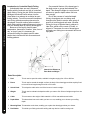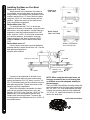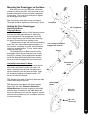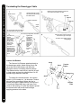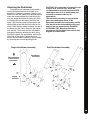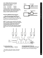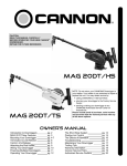
1
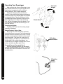
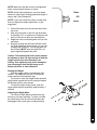
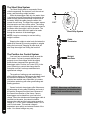
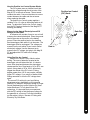
CAUTION:
READ THIS MANUAL CAREFULLY
BEFORE OPERATING YOUR NEW CANNON®
DOWNRIGGER.
RETAIN FOR FUTURE REFERENCE.
MAG 20DT/HS
MAG 20DT/ts
NOTE: Do not return your CANNON® Downrigger to
your retailer. Your retailer is not authorized to repair or
replace this unit. You may obtain service by:
• calling CANNON® at 1-800-227-6433;
• returning your downrigger to the Factory Service
Center;
• sending or taking your downrigger to any
CANNON® Authorized Service Center on
enclosed list.
Please include proof of purchase, serial number
and purchase date for warranty service with any
of the above options.
OWNER’S MANUAL
Introduction to Downriggers
MAG 20 DT New Features
Mounting Your Downrigger
Terminator & Line Release
Cannon Uni-Release
Attaching the Rod Holder
Wiring Your Downrigger
Powering Multiple Downriggers
Operating Your Downrigger
pg. 2
pg. 3
pg. 4-7
pg. 8
pg. 8
pg. 9
pg. 10
pg. 11
pg. 12
The Short Stop System
Positive Ion Control
The Effects of Blowback
Troubleshooting
Maintaining Your Downrigger
Trolling Tips
Warranty Information
Cannon Service Policy
Authorized Service Centers
pg. 14
pg. 14
pg. 16
pg. 17
pg. 17
pg. 18
pg. 19
pg. 19
See List
Introduction to downriggers
Introduction to Controlled Depth Fishing
Undoubtedly there are many fishermen
familiar with the methods and use of controlled
depth fishing. During the mid 1960's the state of
Michigan introduced Pacific salmon into the
Great lakes in an attempt to revitalize its sport
fishing industry. From this successful transplant,
new fishing techniques and equipment were
developed. One such method was controlled
depth fishing which enabled fishermen to place a
lure at a desired depth by utilizing downriggers.
Because of the varying factors (water
temperature, thermocline, weather, tides, time of
day, or time of year) it is necessary for
successful fishing to maintain specific water
depths that coincide with fish movements and
feeding patterns.
One essential feature of the downrigger is
the depth meter or gauge that indicates lure
depth. This allows the angler to control as well
as return to specific depths where fish have
been caught.
Due to the success of controlled depth
fishing, downriggers are now being used
throughout the world to catch a wide variety of
species in both fresh and salt water. Whether
fishing for blues off Rhode Island, walleyes in
Lake Erie, sailfish off the coast of Florida, or
stripers in Tennessee, the use of downriggers
will make your fishing more successful and more
enjoyable.
Attach Line Release to
Rear Hook on Weight
Parts Description
1. Reel
This is used to spool the cable, available in lengths ranging from 150 to 400 feet.
2. Boom
This is used to extend the weight out from the body of the downrigger and has a pulley fixed
to its end. Boom lengths range from 24 to 53 inches.
3. Swivel Head
This relays the cable at the end of the boom to lower the weight.
4. Weight
This is used to maintain the depth at which you want to fish. Sizes of weights range from 4 to
20 lbs.
5. Cable
This connects to the weight. Cable material is 150 lb. test stainless steel cable.
6. Depth Meter
This determines how much cable you have run out, enabling you to choose your trolling
depth.
7. Mounting Base This attaches to the boat, enabling you to place the downrigger where you choose.
8. Rod Holder
2
This holds your fishing rods while trolling and may also be used for storing rods.
Magnum Power
The Mag 20 DT/HS and Mag 20 DT/TS feature
improved tolling weight capacity, retrieval rate,
and quality. The Mag 20 DTs can now
accommodate trolling weights up to 20lbs. The
newly improved Mag 20 DTs also feature a high
retrieval rate up to 250 feet per minute.
Mag 20 DT/TS Features
The Mag 20 DT/TS (Tournament Series) has an
improved appearance featuring a sleek metallicwhite finish. An extremely durable stainless steel
spool allows for you to outfit your downrigger with
monofilament or “super line”, eliminating the fishspooking vibration and harmonics of conventional
downrigger cables. With a heavy-duty, brushed
stainless steel telescopic boom, adjustable rod
holder, and an Off-Shore Release included, the
Mag 20 DT/TS is designed specifically for
tournament level fishing.
Battery Alarm
The Mag 20 DT will now beep every two
seconds if the battery voltage drops below 9 volts.
Remote Operation with CannonLink
Your Mag 20 DT has the ability to be operated
remotely. Utilizing Humminbird Fishing systems
featuring CannonLink, you can control up to 6
Mag 20 DT/HSs and/or Mag 20 DT/TSs
simultaneously. CannonLink gives you the ability
to cycle downriggers up and down, bottom track,
change depth, monitor speed and temp* (with
Cannon Speed & Temp Sensor), and adjust
Positive Ion Control from your Humminbird Fishing
System (Matrix™, 700, and 900 Series).
CannonLink Details
The Mag 20DTs connect to the Humminbird
unit with the #019095 Mag 20 Master Cable. This
cable has an eight-pin plug on one end and a fivepin plug on the other. The eight-pin plugs into the
fish finder communication port. Additional Mag 20
DTs are connected to each other in a chain with
the #019634 Mag 20 Remote Cable. The last
downrigger in the chain must be terminated with
the #609198 Endcap plug that comes with the
Mag 20 Master Cable. This plug completes the
loop allowing the fish finder to get depth and mode
information from the Mag 20 DTs. Additional
information can be found with the Humminbird fish
finder.
NEW FEATURES
Mag 20 DT New Features
The details of CannonLink are described in full
in your Humminbird owner’s manual. Any one or
all Mag 20 DTs can perform these features with
CannonLink only from Cannon:
•
Set PIC voltage in 1/10ths of volts
•
Go to depth (feet or meters)
•
Adjustable descent and retrieve speeds
•
Cycle mode; includes upper depth, lower
depth and time at depth
•
Bottom-contour following mode, includes wave
height, distance above the bottom
•
All up (brings all the weights to the surface
immediately)
•
Park height (allows you to set individual
heights to park the ball above the water)
•
Disconnect alarm sounds if the remote cable
is accidentally unplugged
The Mag 20DTs communicate through an
optically isolated NMEA 0183 standard interface.
Each unit is both a listener and a talker to the next
unit in the chain. The endcap plug sends the last
talker’s broadcast back to the first listener/talker,
which is usually the fish finder. Only two sentence
headers are used: the standard NMEA
‘$SDDBT’ (SONAR Data Depth Below
Transducer) for bottom following, and
‘$PCMAG’ (Proprietary Cannon MAG) for system
control. Several features have been included in
the remote interface that would allow the electromechanical system to be used for other types of
applications.
*Note: The CannonLink system outputs data from only one single
Speed & Temp Sensor Fish.
3
MOUNTING & SETUP
Downrigger Mounting on Boats
A downrigger should be mounted where ever it
is easy to operate and observe. You want to be
able to see your fishing rod and to react quickly.
So, choosing a good spot to mount your
downrigger on your boat is 99% of the job.
Due to the great variety of boats available,
mounting your downrigger can be a dilemma.
Having proper mounting accessories is essential.
Cannon has a complete line of mounting
accessories to conveniently mount your
downriggers on any boat.
Mounting Accessories
Deck Plates are necessary when extra
strength must be added to the base material of
the boat and for attaching the downrigger to other
mounting accessories.
Gimbal Mounts are designed to fit mediumsized flush mounted rod holders built into the
gunwale of many larger fishing boats and
cruisers. Only sturdy, high quality rod holders
should be used for this temporary mounting
system. Gimbal mounts are available in 9” or 12”
post lengths.
Arrows
Indicate
Mounting
Locations
Deck Plate
Gimbal Mount
Clamp Mounts can be mounted at the
junction of two rail sections with the aid of two ¼”
pieces of plywood. They will protect your rail from
any marks from the clamp and provide a non-slip
surface.
Clamp Mount
4
You can also use these for mounting to a
very narrow side gunwale. There is a plate
provided for back-up with bolts and washers. If
the gunwale compartment is foamed in, then
wellnuts should be used. It is also recommended
to install two additional flat head screws through
the top plate for stabilization (you will need to
drill and countersink).
Side/Rail on T-Section
MOUNTING & SETUP
Side Rail Mounting
Side/Rail mounts can be mounted to a
welded T section. They can also be used at the
two rail section butt joint. In both installations it is
recommended to use a non-slip material, such
as rubber or a thin wood sheet, between metal
surfaces.
Side/Rail on Gunwale
NOTE: In no case should this mount be used on
fiberglass ¼" thick or less unless it is foamed in.
Pedestal Mounting
Pedestals are used wherever additional height is
needed for ease of operation or to clear
obstructions, such as handrails.
Caution: When using a pedestal mount or
side/rail mount, do not extend the telescopic
boom on your Mag 20 DT. The increased
leverage will cause excessive strain and
possible failure of the mount.
Pedestal for Additional Height
5
MOUNTING & SETUP
Installing the Base on Your Boat
Decks up to 7/16" thick
Where access to the underside of the deck is
not available, the mounting base can be mounted
using wellnuts. Use the base as a template to mark
locations and drill four 1/2" holes. Mount the base
using four 1/4-20 x 4" truss head screws and four
wellnuts. Tighten the screws so the wellnuts are
firmly compressed as pictured.
Decks thicker than 7/16"
For decks thicker than 7/16", or where the
underside of the deck is accessible, mount the base
with screws, nuts, and washers. Use the base as a
template to mark the locations and drill four 9/32"
holes. Use four 1/4-20 x 4" truss head screws and
four each flat washers, lock washers, and nuts.
Fasten the base to the deck as pictured. NOTE:
Wellnuts cannot be used on decks thicker than
7/16".
Decks thinner than 1/4"
Use a Cannon deck plate to prevent deflection
and add stability to decks thinner than 1/4". Use the
deck plate as a template to
mark the hole locations.
Deck up to 7/16" Thick
Decks up to
7/16" Thick
Base
Wellnuts
Decks Thicker
Than 7/16" Thick
Base
Washer, Lock Washer,
and 1/4-20 Hex Nut
Screws
Deck Plate
Deck Thicker Than 7/16”
Wellnut
If access to the underside of the deck is not
available, the deck plate can be mounted using
screws and wellnuts. Drill 1/2" holes. Use four 1/420 x 2" flat head screws and four wellnuts to mount
deck plate as pictured. Tighten the screws so the
wellnuts are firmly compressed.
Where the underside is accessible, the deck
plate can be mounted using screws, nuts, and
washers. Drill 9/32" holes. Use four 1/4-20 x 2" flat
head screws, nuts and washers (flat and lock).
Fasten plate to deck as pictured. To secure the
mounting base to the deckplate use four 1/4-20 x 2"
truss head screws.
6
Washers, Lock
Washers, Screws,
& Nuts
NOTE: When using the telescopic boom, we
strongly recommend the use of a deck plate
on all boats to provide adequate stability for
the downrigger.
The Low-Profile Swivel Base mounting follows the
same procedure as for the deck plate except that
four 1/4”-20 x 2 1/2" truss head screws are used
to fasten the mounting base and four additional
1/4”-20 x 2 1/2" truss head screws fix the swivel
base to the boat deck.
Low-Profile Swivel Base
Slide body over the lip of the base, with boom
outboard or facing the stern. Lift Lock Knob to hold
threaded shaft clear of base until body completely
covers base. Turn Lock Knob clockwise to tighten
the downrigger to the base.
Tip: Periodically check base to ensure integrity.
The base should be replaced at least every 5 years.
Lock Knob
Setting Up Your Downrigger
Attaching the Boom
Telescopic Boom
The intermediate section of the telescopic boom
must be extended approximately 5" before the
boom locking screw can engage the hole in the
boom. Slip the boom end into the frame and align
the holes. Secure with boom locking screw.
To adjust boom length, with the boom extending
away from you, rotate clamps approximately 1/4
turn counter - clockwise to unlock, and slide boom
section to desired position. To lock, rotate clamp
clock-wise until tight.
The Standard 24 Inch Boom inserts into the
downrigger frame. Be sure that the boom is held
securely by seating it firmly against the shoulder
inside the fame and fastening the boom locking
screw such that it engages the hole in the boom.
3/4"-Long Boom
The Locking Screw Must
Engage Hole in Boom
Clamps
Standard 24"
Boom
Assemble Swivel Head To Boom
Insert the telescopic boom-end into the boomalign holes and fasten in place with a #8 x 5/8
screw. Spread the swivel head side plates and
slip the assembly over the boom end axle. Snap
the assembly together and install two #4 x 1/2"
screws into the swivel head.
TIP: Adjusting the angle of the boom head can help
control cable wrap on the reel.
TIP: Whenever downriggers with boom lengths
beyond 24" are used, Cannon's Retro-Ease
Weight Retriever will make bringing in the weight
safe and easy. It attaches to the cable below the
boom end allowing you to pull the weight to yourself
without having to lean way out or collapse the boom
to reach the weight.
MOUNTING & SETUP
Mounting the Downrigger on the Base
Swivel Head
Boom
#8 x 5/8"
Screw (1)
#4 x 1/2"
Screws (2)
7
TERMINATOR & LINE RELEASE
Terminating the Downrigger Cable
Rubber Cushion
Cable
Examine the top of the terminator and note the
order shown in the detail to run cable.
Unwind about 2 feet of cable
and thread the cable through
the rubber cushion.
CABLE IN
CABLE IN
Attach to terminator.
CABLE OUT
Snap &
Swivel
Tip: A set of pliers with wire cutters is
recommended for this part of setup.
TIP: Use only straight cable, not kinked.
Lead cable into
HOLE A.
Pull six inches of
cable through.
Thread cable
through swivel,
then up into
bottom of the
terminator.
Lead cable out of
HOLE B and into
HOLE C. Push the
cable until its end
touches the inside
of the terminator
hook.
HOLE A
Slide the cushion over the top of the
terminator and give it a test pull.
Tighten cable
by squeezing
terminator
until it snaps
shut. Then
pull at top and
bottom until
drawn tight.
Make sure
that the
cable
threads the
hook.
The cable is set to attach a Cannon
Trolling Weight.
Swivel
Cannon Uni-Release
Close
The Cannon Uni-Release attaches directly to
the downrigger weight. Attach fishing line to the
clip at the end of the release, and then click
through a series of increasing tension settings.
The release can be used with any test line on salt
or fresh water and may be adjusted from 2 to 22
pounds of grip tension on the line.
To change line release tension, turn tension
knob to (+) to increase or (-) to decrease. Tension
also may vary according to where the line is
placed in the grips. Higher tension is on the line if
it is set back toward the hinge, and lower if set
closer to the opening. To open the release, spread
the release arms with thumb and forefinger
applying pressure to the sides.
8
Open
Tension
Adjust
Fishing Line
Open
Gripper
Pads
The positive lock rod holder incorporates a
locking disk that allows the rod holder to be
aligned in 15 degree increments. Slide the rod
holder tube into the clamp to the desired position
within the recommended area (see below). Be
sure the angled shoulders are facing up. Place
the locking disk into the mating recess of the
frame. Slip the clamp arms in place where the
obround tab on the disk fits into the slot on the
clamp. Slide the star washer between the arm of
the clamp and the frame. Place the flat washer
onto the bolt. Then insert the bolt with washer
through the clamp by entering the disk, going
through the frame, the star washer, and out the
other side of the clamp. Tighten the nut to
secure the rod holder. Reposition the rod holder
by loosening the nut and adjusting the tilt.
Single Rod Holder Assembly
Recommended
Area to Clamp
Rod Holder
CAUTION: This rod holder is intended for use
of up to 30 lb. test line only, and is not
recommended for use with any tackle IGFA
rated higher than 30 lb. A safety strap (not
included) is recommended for all
applications.
The rod holder assembly is not warranted
when used with tackle above 30 lbs.
Equipment placed in the rod holders and the
loss thereof is the responsibility of the user
and is in no way warranted by JOHNSON
OUTDOORS, INC. Mounting must be in
accordance with the above instructions and
diagram to be warranted.
ATTACHING THE ROD HOLDER
Attaching the Rod Holder
Dual Rod Holder Assembly
Star Washer
Placement
Angled
Shoulder
9
WIRING YOUR DOWNRIGGER
Wiring Your Downrigger
Your Boat's Electrical Condition
It is important to make sure that your boat is
properly set up before installing your Mag 20 DT
with Positive Ion Control (PIC). Whenever a boat
is in water, various submerged parts interact to
create weak electrical currents. These weak
electrical currents must be controlled to extend
the life of the boat's metal parts and ensure a
good fish catching environment.
Check the zinc sacrificial anodes on your boat
and on the outboard/outdrive. If they are more
than 50% dissolved they should be replaced. Any
coating of slime or growth should be cleaned off.
All metal parts including the hull (if metal) must be
interconnected by a grounding wire. This includes
motor shafts, outdrives, and through hull fittings.
If your boat and zincs are set up correctly, the
voltage on the stainless steel downrigger wire of
your Mag 20 DT should be positive when in
contact with the water. The following tips can be
useful:
•
•
•
•
•
10
Use Cannon vinyl coated lead weights. Lead,
if not pure, can produce negative charges.
Use the trolling weight insulators supplied with
your downrigger. This insulates your weight
from the positive charge on the cable. This will
also ensure that the trolling weight will stop at
water level when retrieved.
The cable on your downrigger should be
replaced every 2 years. Etching of the cable
can weaken it physically and electrically.
In saltwater, make sure the sacrificial zincs
are replaced when half dissolved. This
ensures that the boat will run with a neutral or
slightly positive charge. Clean zincs on a
regular basis with a non-corrosive brush.
Always make sure the boat is properly
grounded to the water. This will help ensure
proper PIC voltage on the cable and that the
Short Stop will function properly.
Note: You must unplug the Mag 20 DT to check
the natural voltage on the reel cable.
Electrical Specifications & Wiring
Instructions
The Mag 20 DT is rated at 25 amps (full load),
12 volts DC and is protected by a 30 amp manual
reset circuit breaker (located under motor housing).
Be sure to measure the battery voltage of your boat.
WARNING! - DO NOT RUN THIS DOWNRIGGER
ON A 24 VOLT BATTERY SYSTEM. THIS WILL
DAMAGE THE UNIT AND VOID YOUR
WARRANTY.
Connecting to the Battery:
It is strongly recommended that a fuse or
manual-reset circuit breaker be installed at the
battery on the positive lead of the power cable or
that you connect the downrigger to a battery
selector switch. (See Fuse and Wire Specifications)
Connect the positive lead (RED) to the (+) post on
your battery or the downrigger will not operate. Use
the new quick disconnect plug to remove the
downrigger without touching the battery.
NOTE: It is strongly recommended to power your
Mag 20 DT with a Deep-Cycle marine battery. Only
run a Mag 20 DT from a Starter battery if is
recharged by an alternator while trolling with the
outboard motor.
Tip: Control degradation of the power cables and
limit corrosion by using Cannon Ox-Not antioxidant gel on all connections.
Battery
Battery
Fuse Holder
Circuit Breaker
Red ( - )
Powering Multiple Downriggers
When operating multiple Mag 20 DTs, run a
maximum of 2 downriggers per dedicated
battery. The advanced features of the Mag 20 DT
can keep the unit working virtually all the time. (See
below for the recommended wiring setup.)
WIRING YOUR DOWNRIGGER
FUSE / BREAKER SPECIFICATIONS:
30 Amp, 32 Volt, waterproof, fast blow.
WIRE SPECIFICATIONS:
0-15 ft.
(0-5 meters)
10 gauge
15-25 ft. (5-8 meters)
8 gauge
25-30 ft. (8-9 meters)
6 gauge
CAUTION: When using wire longer than that
provided with your unit, follow the above chart.
When running more than 30 feet from the
battery, contact a qualified electrician.
NOTE: To ensure proper operation of your Mag
20 DT, ground its battery to your boat’s electrical
system’s ground. Malfunctions with the PIC,
communication between units, or loss of
operation result from faulty grounding. Always
check to see if your boat is properly grounded
first.
Red
(+)
Black ( – )
Typical Operating Time*:
1 Mag 20 DT per battery – 24 hours.
2 Mag 20 DTs per battery – 10 hours.
Connect
Multiple
Batteries in
Parallel
FOR MAXIMUM PERFORMANCE:
Use Minn Kota Group 27 or 31 sized, Deep-Cycle
marine batteries. For extended battery life, add a
Minn Kota on-board, DC alternator charger.
*Time based on lab results using a 15lb weight
and Deep-Cycle batteries. Actual run time will
vary.
11
OPERATING YOUR DOWNRIGGER
Operating Your Downrigger
After mounting the Cannon downrigger to your
boat, release some line from your rod and reel so
that the lure is anywhere from 5 to 100 feet
behind the boat. Tthis is called drop back.
Attach the fishing line firmly into the line
release. Press and hold the toggle switch down to
lower the weight to the desired depth as indicated
on the depth meter. Place the fishing rod in the
rod holder and reel up the slack so that your rod
has a slight bend in it. When a fish strikes the
lure, the line will separate from the release. Then
you will be free to fight the fish and bring it in on
your rod and reel.
To Lower
Weight
Clutch Knob
Lowering the Weight
The Mag 20 DT can lower the trolling weight
manually or powered.
Manual Descent: Fast or Slow
By turning the clutch knob gently clockwise
(toward the boom), you can let your trolling weight
descend as fast or as slowly as you wish. Turning
the knob counterclockwise (away from the boom)
stops the weight. This gives you control to let it
plunge rapidly or sink slowly to a predetermined
trolling depth. With multiple downriggers, you
could start all your weights creeping down, one at
a time, and then stop them each in turn.
3-Position
Motor Switch
Powered Descent: One speed fits all
Hold the toggle switch down until the weight
reaches the desired depth and release. The motor
will stop when switch is released or moved to the
neutral position.
3-Position
Motor
Switch
12
NOTE: Actual fishing depth may vary from depth
shown on meter due to trolling speed and weight of
cannon ball. (See "Blowback")
NOTE: If your reel continues to slip no matter how
hard you tighten the brake adjust knob, try this
suggestion.
Raise
Off
Lower
1. Unwind the cable from the reel and remove the
set screw.
2. Align set screw hole in reel with reel shaft hole
by inserting 3/16" or smaller rod. Rotate the reel
until you feel the rod drop into the shaft hole.
3. Replace the set screw and tighten until you feel
resistance.
4. By gently rocking the reel back and forth while
you finish tightening the set screw, you can feel
it engage the shaft hole. The half dog point on
the set screw MUST enter the shaft hole, not
just be tightened against the shaft.
OPERATING YOUR DOWNRIGGER
NOTE: Make sure that the clutch is well tightened
when using powered descent or ascent.
Caution: The brake adjust knob (clutch) should
be adjusted so that it is tight enough to hold the
weight and the lure at the speed you are
trolling. Over tightening may cause damage to
your downrigger when weight hangs up on
bottom structure or other obstacles.
Raising the Weight
Push the toggle switch up momentarily and
release. The weight will rise until it reaches the
surface and then automatically stop.
If you want to raise the weight farther push the
toggle switch up and hold until the weight reaches
the desired position, then release.
To stop the weight during ascent, push the
toggle switch down momentarily (approximately 1
second).
Adjusting the Depth Meter
The Cannon Depth Meter provides non-slip
accuracy, plus easy resetting. To reset, just slide
the meter away from the reel until the gears are
disengaged. Spin meter gear to change setting.
Depth Meter
13
THE SHORT STOP SYSTEM
The Short Stop System
The Short Stop system is composed of three
critical components: the electronic unit, the reel set
screw, and the trolling weight insulator.
While the downrigger cable is in the water, there
is a minute electrical current that flows between the
cable and the grounded metal boat components in
the water. When the cable clears the water, this
current flow will stop. The Short Stop system senses
this interruption and turns off the motor. The trolling
weight insulator is used to break the cable contact to
the water while the weight is still in the water. The
reel set screw allows the circuit path to be made
through the structure of the downrigger.
NOTE: It may be necessary to use two trolling
weight insulators.
Stopping the weight at water level eliminates the
cable strain caused by bouncing weights or weights
hitting the boom end. Stopping at water level will
also keep the weight from hitting the boat hull.
The Positive Ion Control System
Your boat has an electrical charge around the
hull in water. If a boat is properly bonded and
properly zinced, that charge should be slightly
positive when measured from ground to the
downrigger cable. Positive Ion Control (PIC) is the
use of electricity to control that charge and its
fluctuation so that it is always maintained at a
specified set voltage.
1/16"
Short Stop System
Cable
Terminator
Weight
Insulator
The practice of setting up and maintaining a
slight positive charge on fishing gear has been used
by commercial fishermen for many years. This
practice has enabled some fisherman to increase
yield when used along with other good fishing and
boating practices.
14
Cannon’s electric downriggers offer fishermen a
big advantage in being able to stabilize and control
the positive charge around their boat. Because of
the Lexan® construction of the frame, Cannon
downriggers are insulated from your boat’s hull
charge. When the stainless steel downrigger cable is
lowered into the water, the natural ionization
between the cable and the boat creates a positive
charge of 0.7 to 0.9 volts in saltwater and 0.3 to 0.6
volts in fresh water. This natural voltage is
dependent upon salinity and mineral content of the
water. Your actual voltage may vary.
NOTICE: Short stop and Positive Ion
Control features do not function when
spooled with monofilament or super
lines.
Measuring the Natural Electrolysis and PIC
Voltage on Your Boat
A voltmeter with a scale of zero to one volt will
measure the natural electrolysis. Place the ground
lead of the meter on the motor or the battery
ground. Place the positive lead on the stainless
steel downrigger cable while it is in the water. The
downrigger must be unplugged. The voltage you
measure on the volt meter is your boat’s natural
electrolysis voltage. Use the same set up to
measure the PIC voltage; just plug in the Mag 20
DT and adjust the PIC knob to the voltage
desired.
Positive Ion Control
(PIC) Knob
Data Out
POSITIVE ION CONTROL
How the Positive Ion Control System Works
The PIC system uses an internal circuit that
passes the voltage through the drive train of the
Mag 20 DT to the reel set screw. The set screw
contacts the cable. Care must be taken to ensure
contact between the cable and the set screw
when replacing the cable.
The positive Ion Control system applies a
variable 0.2 to 1.2 volts on the trolling cable at all
times. To adjust the Positive Ion Control, simply
turn the PIC knob on the back of the Mag 20 DT
housing (see below).
Data In
Using Positive Ion Control
Positive Ion Control is very effective when
trolling. The zone of attraction created at the
downrigger wire will attract the fish. It is best to
use a short drop back between the downrigger
release and the lure. Drop backs of 10 to 20 ft. are
typical. A drop back of 50 to 100 ft. will entirely
negate the effects of the PIC circuit. Fishing
depths greater than 125 ft. may require a slightly
higher PIC voltage. If you return to shallow water
fishing remember to turn the PIC voltage down
again.
The correct PIC setting for your best fishing
advantage varies, depending on fish type and
location. For example, the proper setting for Puget
Sound Steelhead may not be effective for Great
Lakes Steelhead. To fully benefit from PIC
technology, it is important that you experiment
with the PIC setting to find the proper voltage for
the gamefish in your area. For more information
on this subject, refer to “Secrets of Fishing with
Electricity” by Ollie Rode.
15
Simply stated, blowback is what happens to
the downrigger weight when you pull it through the
water behind your boat. As your speed increases,
so does the horizontal distance between the
weight and your downrigger. The faster you go,
the farther the weight is behind you. The farther
the weight is behind you, the shallower the weight
is.
The following charts provide you with
blowback information for three sizes of Cannon
downrigger weights pulled at three different
speeds with no lures attached and with no current.
Current drag, water salinity and the use of nonCannon products will affect your actual trolling
depth.
As an example, the first chart shows that if you
are trolling at 4 MPH with an 8 pound weight and
you have 100 FT. of cable in the water with no
current; the downrigger ball is actually at a depth
of about 80 FT.
8-Lb. Weight at 2, 4, and 6 MPH
2 MPH
Actual Depth of Weight (ft.)
Blowback
Blowback Charts
Blowback
4 MPH
6 MPH
Amount of Cable in Water (ft.)
10-Lb. Weight at 2, 4, and 6 MPH
2 MPH
ActualDepth of Weight (ft.)
4 MPH
6 MPH
Amount of Cable in Water (ft.)
12-Lb. Weight at 2, 4, and 6 MPH
2 MPH
Actual Depth of Weight (ft.)
16
4 MPH
6 MPH
Amount of Cable in Water (ft.)
PROBLEM:
Up or down will not work.
SOLUTION:
Check the battery cable polarity then check
the battery voltage. A properly connected and
charged battery is important for safety and for
proper operation of the downrigger.
PROBLEM:
The Mag 20 DT/HS \ Mag 20 DT/TS fails to
continue running after toggle switch is pushed
up and held momentarily, while cable is still in
water, or is having problems with the PIC
voltage.
SOLUTION:
Make sure your boat is properly bonded. A
boat that is properly bonded has an electrical
path from the negative battery terminal to all
metal parts on the boat that contact water.
Additionally, in saltwater the boat must be
properly zinced to show a natural electrolysis
voltage of 0.7 to 0.9 volts. The voltage supply
to your downrigger must also be bonded to
the boat.
Maintaining Your Downrigger
Periodically, lightly grease the thrust bearing
and bearing race found behind the clutch knob.
Replace the cable at least every two years.
There are no other user serviceable parts on
the Mag 20 DTs. Your warranty will be void if
the seal on your unit is broken. For repairs or
servicing your downrigger refer to the
Warranty Information section of this booklet.
TROUBLESHOOTING & MAINTAINING
Trouble Shooting
PROBLEM:
Clutch slips
SOLUTION:
The set screw in the reel may have come
loose off the shaft. Follow the instructions
below:
1) Unwind the cable from the reel.
2) Remove the set screw.
3) Align the set screw hole in the reel with the
hole in the reel shaft by inserting a 3/16" or
smaller rod and rotating the reel until you feel
it drop into the shaft hole.
4) Replace the set screw and tighten until you
feel resistance.
5) By gently rocking the reel back and forth while
tightening the set screw, you can feel it
engage in the shaft hole. The half dog point
on the set screw must enter the hole in the
shaft; not just be tightened against the reel
shaft.
6) The set screw should be about 1/16" above
the top of the hole when it is properly seated
(not so for TS models). The contact between
the stainless steel cable and the set screw is
important for proper operation of the Positive
Ion Control system.
17
TROLLING TIPS
Ten Good Trolling Tips
1) Test your lures over the boat side before
sending them down and back. Do this to make
sure the lure wiggles and wobbles properly
without going belly up or wandering off. Some
lures can be adjusted, fine tuned actually, to
impart maximum action. For example, a slight
bend in the tail of a spoon or twist of the hook eye
in the nose of a plug can make a noticeable
difference in how the lure performs.
Also, when running two or more lures, make sure
the offerings are compatible. Lures that run out of
harmony with each other are bound to tangle and
that means wasted time to straighten out the
mess. Testing them first will avoid the problem.
2) Consider different sizes, shapes, and colors
of lures. No one has ever figured out with
precision what makes a fish strike or snub a lure.
There is no doubt, that matching the forage
(minnows, crayfish, etc.) in color, shape, action,
and size can help trigger those strikes from
hungry fish. On the other hand, if fish such as
bluegills, small mouth bass or Coho salmon are
protecting spawning beds, they may attack
whatever is threatening. So, bright colors in lures
may out produce bland colors.
3) Vary trolling speeds. Goosing the engine
now and then or slowing to a crawl every so often
will change the action of the lures and may get
fish to strike them.
4) Vary trolling patterns and lead lengths. The
amount of line you let out often determines how
deep the lure will run and, to some extent, what
degree of action it will impart. For starters,
consider running lures about ten feet behind
downrigger weights. If flat line trolling, put them
back about fifty feet, then experiment depending
on what the fish do.
Trolling patterns affect lure action too, that is
why some anglers like to wheel a lazy S course.
On turns, outside lures will speed up momentarily
while inside lures hang for a moment or two. Fish
may nail lures that change speeds. Also, zigzag
patterns allow for more water coverage, plus it
keeps lures out of propeller boil, an important
consideration for browns and other wary species.
18
5) Locate fish on a vertical plane. Place lures
in areas where fish might be. Skilled fishermen
call these areas the “strike zones”. They include
the edges of the week beds, structure along
bottom, drop-offs, preferred temperature of the
target species, and the thermocline. Remember
that fish occupy certain areas for certain reasons
(sources of food, protective cover, preferred
temperatures, etc.).
6) Consider special knots and swivels. A
good ball bearing swivel will all but eliminate line
twist and will aid in getting maximum performance
from a lure. Many anglers add the tiny swivels to
split rings already on the lure itself. On the other
hand, a swivel may dampen the action of a
sensitive lure, such as a Rapala. Some fisherman
tie tiny improved cinch or loop knots. Loop knots
in particular may enhance up and down and side
to side action of lures. Any good fishing manual
will explain how to tie these and other knots.
7) Consider releases for flatline trolling. A
good tip is to secure a piece of downrigger cable
or heavy monofilament to the water ski hook or
handle below the transom of most boats. To the
other end of the mono or cable, add a pinch-rrelease. After letting out your lure to the desire
distance, put the rod in its holder, then bend the
tip and secure the fishing line in the release.
8) Add a weed guard. Having trouble with
weeds hanging up lures? Consider tying a threeinch piece of monofilament a foot above the lure.
Leaves, smaller weeds and other debris may
catch here momentarily then fall off to the side of
the lure without tangling. Weedless lures are
another smart consideration. Downrigger cables
are effective weed catchers when trolling for pike,
muskies, or bass in weed-infested lakes.
9) Add a stinger hook. When fish short strike,
slap at lures without becoming hooked, adding a
stinger hook can solve the problem. Simply tie a
treble hook to one end of a four inch piece of
monofilament and then tie the extra hook to the
last gang of hooks on your lure. The stinger hook,
which trails the lure, provides extra insurance.
10) Keep hooks sharp. Some of the best
fishermen sharpen all hooks after every fish
caught. Hooks get dull through both use and
misuse, and probably more fish are lost to dull
points than anything else.
Johnson Outdoors Inc. warrants to the original purchaser that if the
accompanying product (see exclusions below) proves to be defective
in material or workmanship within the following warranty periods,
Johnson Outdoors Inc. will, at its option, either repair or replace same
without charge (but no cash refunds will be made):
1) The boom, motor, and reels, plus all Lexan®* parts, including
but not limited to frames and bases, will be free from defects in
materials and workmanship, subject to normal wear and tear,
for the original purchaser's lifetime.
2) All other items will have 1-year limited warranties from the
date of original retail purchase, except THE FOLLOWING
ITEMS THAT HAVE NO WARRANTY WHATSOEVER: boot
covers, clothing, Dacron line, rubber bands, swivel lock pin,
weights, and wire cable.
This limited warranty may be enforced only by the original
purchaser; all subsequent purchasers acquire the product "as
is" without any benefit of this limited warranty. Repair or
replacement of the product as set forth in this limited warranty
shall be the original purchaser’s sole and exclusive remedy
and Johnson Outdoors Inc.’s sole and exclusive liability for
breach of this warranty.
EXCLUSIONS
This warranty does not apply in the following circumstances:
•
When the product has been connected, installed, combined,
altered, adjusted, serviced, repaired, or handled in a manner
other than according to the instructions furnished with the
product
•
When the motor housing is opened by anyone other than
Cannon® Authorized service repair personnel.
•
When any defect, problem, loss, or damage has resulted from
any accident, misuse, negligence, carelessness, or abnormal
use, or from any failure to provide reasonable and necessary
maintenance in accordance with the instructions of the owner's
manual
LIMITATION AND EXCLUSION OF IMPLIED WARRANTIES AND
CERTAIN DAMAGES
THERE ARE NO EXPRESS WARRANTIES OTHER THAN
THESE LIMITED WARRANTIES. JOHNSON OUTDOORS INC.
DISCLAIMS LIABILITY FOR INCIDENTAL AND CONSEQUENTIAL
DAMAGES, AND IN NO EVENT SHALL ANY IMPLIED
WARRANTIES (EXCEPT ON THE BOOM, MOTOR, REELS, AND
ALL LEXAN®* PARTS), INCLUDING ANY IMPLIED WARRANTY OF
MERCHANTABILITY OR FITNESS FOR PARTICULAR PURPOSE,
EXTEND BEYOND ONE YEAR FROM THE DATE OF PURCHASE
(AND IN THE CASE OF THE BOOT COVERS, CLOTHING, DACRON
LINE, RUBBER BANDS, SWIVEL LOCK PIN, WEIGHTS, AND WIRE
CABLE, JOHNSON OUTDOORS INC. DISCLAIMS ALL IMPLIED
WARRANTIES). THIS WRITING CONSTITUTES THE ENTIRE
AGREEMENT OF THE PARTIES WITH RESPECT TO THE
SUBJECT MATTER HEREOF; NO WAIVER OR AMENDMENT
SHALL BE VALID UNLESS IN WRITING SIGNED BY JOHNSON
OUTDOORS INC.
Some states do not allow limitations on how long an implied warranty
lasts or the exclusion or limitation of consequential damages, so the
above limitation or exclusion may not apply to you. This warranty gives
you specific legal rights, and you may also have other rights that vary
from state to state.
CANNON® SERVICE POLICY
AFTER THE APPLICABLE WARRANTY PERIOD
After the applicable warranty period, or, if one of the above
exclusions applies, Cannon® products will be repaired for a charge of
parts plus labor. All factory repairs, after the applicable warranty
period, carry a 90-Day Limited Warranty, subject to the exclusions and
limitations stated above.
TO ENFORCE WARRANTY OR TO
OBTAIN REPAIRS AFTER WARRANTY
To obtain warranty service in the U.S., the downrigger or part
believed to be defective and the proof of original purchase (including
the date of purchase) must be presented to a Cannon® Authorized
Service Center or to Cannon®’s factory service center in Mankato,
MN. Except as noted below, any charges incurred for service calls,
transportation or shipping/freight to/from the Cannon® Authorized
Service Center or Cannon®’s factory, labor to haul out, remove, reinstall or re-rig products for warranty service, or any similar items are
the sole and exclusive responsibility of the purchaser. Downriggers
purchased outside of the U.S. (or parts of such downriggers) must be
returned prepaid with proof of purchase (including the date of
purchase and serial number) to any Authorized Cannon® Service
Center in the country of purchase. Warranty service can be arranged
by contacting a Cannon® Authorized Service Center listed on the
enclosed sheet, or by contacting the factory at 1-800-227-6433 or Fax
1-800-527-4464. If the necessary repairs are covered by the warranty,
we will pay the return shipping charges to any destination within the
United States.
DO NOT return your Cannon® downrigger or parts to your retailer.
Your retailer is not authorized to repair or replace them.
LIMITED WARRANTY & SERVICE POLICY
CANNON® LIMITED WARRANTY
Major parts, such as the motor and main frame, must be returned
to Johnson Outdoors Inc. in Mankato, Minnesota, or a Cannon®
Authorized Service Center, for repair or replacement. To reduce
shipping costs, we suggest removal of loose parts such as the boom
and rod holders. Small parts that can be easily removed such as the
handle and/or the counter, may be removed from the downrigger and
returned for repair or replacement.
Retain your sales receipt! Proof of purchase must accompany
product when returned.
Return Address:
Johnson Outdoors Inc.
Cannon Division
121 Power Drive
Mankato, MN 56001
FOR YOUR INFORMATION:
Serial No.
Date Purchased
Store Where Purchased
RETAIN THIS SECTION FOR YOUR RECORDS
* Lexan is a registered trademark of General Electric.
19
ENVIRONMENTAL COMPLIANCE STATEMENT:
It is the intention of Johnson Outdoors Inc. to be a responsible corporate citizen, operating in compliance with known and applicable
environmental regulations, and a good neighbor in the communities where we make or sell our products.
WEEE Directive:
EU Directive 2002/96/EC “Waste of Electrical and Electronic Equipment Directive (WEEE)” impacts most distributors, sellers, and manufacturers of consumer electronics in the European Union. The WEEE Directive requires the producer of consumer electronics to take responsibility
for the management of waste from their products to achieve environmentally responsible disposal during the product life cycle.
WEEE compliance may not be required in your location for electrical & electronic equipment (EEE), nor may it be required for EEE designed and intended as fixed or temporary installation in transportation vehicles such as automobiles, aircraft, and boats. In some European Union
member states, these vehicles are considered outside of the scope of the Directive, and EEE for those applications can be considered excluded
from the WEEE Directive requirement.
This symbol (WEEE wheelie bin) on product indicates the product must not be disposed of with other household refuse.
It must be disposed of and collected for recycling and recovery of waste EEE.
Johnson Outdoors Inc. will mark all EEE products in accordance with the WEEE Directive. It is our goal to comply in the collection, treatment, recovery, and environmentally sound disposal of those products; however, these requirement do vary within European Union member states. For more information about where you should dispose of your waste equipment for recycling and
recovery and/or your European Union member state requirements, please contact your dealer or distributor from which your product was purchased.
To download product manuals or purchase Cannon products from an authorized dealer, please visit our web page at
www.cannondownriggers.com
Johnson Outdoors, Inc. / Cannon Division
121 Power Drive, Mankato, MN 56001
1-800-227-6433
© 2008 Johnson Outdoors, Inc. All rights reserved.
All CANNON Downriggers are covered by US Pat.D-269, 992. Copyright 2006 Johnson Outdoors, Inc. All rights reserved.
Conforms to 89/336/EEC (EMC) under standards EN 55022A, EN 50082-2 since 1996 LN V9677264
WARNING: This product contains chemical(s) known to the state of California to cause cancer and/or reproductive toxicity.
20
Form No. 3397101 Rev D