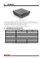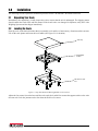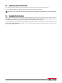
1
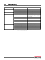
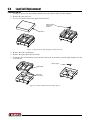
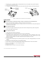
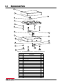
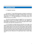
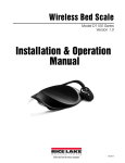
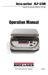
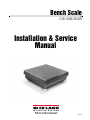
Bench Scale CW-90B/90XB Installation & Service Manual 155605 Contents 1.0 Introduction.................................................................................................................................. 1 1.1 CW-90B/90XB Bench Scale Specifications . . . . . . . . . . . . . . . . . . . . . . . . . . . . . . . . . . . . . . . . . . 1 1.2 Safety . . . . . . . . . . . . . . . . . . . . . . . . . . . . . . . . . . . . . . . . . . . . . . . . . . . . . . . . . . . . . . . . . . . . . . . . 2 2.0 Installation ................................................................................................................................... 3 2.1 2.2 2.3 2.4 Unpacking Your Scale. . . . . . . . . . . . . . . . . . . . . . . . . . . . . . . . . . . . . . . . . . . . . . . . . . . . . . . . . . . Leveling the Scale . . . . . . . . . . . . . . . . . . . . . . . . . . . . . . . . . . . . . . . . . . . . . . . . . . . . . . . . . . . . . . Connecting the Load Cell Cable . . . . . . . . . . . . . . . . . . . . . . . . . . . . . . . . . . . . . . . . . . . . . . . . . . . Grounding the Scale Base . . . . . . . . . . . . . . . . . . . . . . . . . . . . . . . . . . . . . . . . . . . . . . . . . . . . . . . 3 3 4 4 3.0 Calibration ................................................................................................................................... 5 4.0 Troubleshooting ........................................................................................................................... 6 5.0 Load Cell Replacement................................................................................................................ 7 6.0 Replacement Parts ..................................................................................................................... 9 CW-90B/90XB Bench Scale Limited Warranty ...................................................................................... 10 Technical training seminars are available through Rice Lake Weighing Systems. Course descriptions and dates can be viewed at www.ricelake.com/training or obtained by calling 715-234-9171 and asking for the training department. © Rice Lake Weighing Systems. All rights reserved. Printed in United States of America. Specifications subject to change without notice. Rice Lake Weighing Systems is an ISO 9001 registered company. November 19, 2014 i Rice Lake continually offers web-based video training on a growing selection of product-related topics at no cost. Visit www.ricelake.com/webinars. ii CW90B/90XB Bench Scale Installation Manual 1.0 Introduction This manual provides reference information to install and wire the CW-90B/90XB bench scale which is shown in Figure 1-1. Figure 1-1. CW-90B/90XB Bench Scale The CW-90B and CW-90XB are both NTEP-certified and available in a 10" x 10" (254 mm x 254 mm) and 12" x 12" (304 mm x 304 mm) platform with capacities from 5 to 100 lb (2.5 to 50 kg). The light capacity scales are constructed with 304 stainless steel to withstand many years of rugged use. The CW-90B comes with an aluminum environmentally sealed load cell. The CW-90XB comes with a stainless steel and hermetically sealed IP69K load cell. 1.1 CW-90B/90XB Bench Scale Specifications Table 1-1 lists the CW-90B and CW-90XB model specifications. CW-90B Load Cell Aluminum environmentally sealed Overload Protection 5 point, independently adjusted Cable Length 34 inch or 10 ft (3 m) - 6 wire shielded Output Impendance 350 Maximum Overload 180 to 200% depending on capacity Compensated Temperature Range 14°F to 104°F (-10°C to +40°C) CW-90XB IP69K Stainless steel Dimensions/Capacities Size Capacity Height 10" x 10"/254 mm x 254 mm 5, 10, and 25 lb/2.5, 5, and 12.5 kg 4.25"/108 mm 12" x 12"/304 mm x 304 mm 25, 50, and 100 lb/12.5, 25, and 50 kg 4.25"/108 mm Table 1-1. 10" x 10" and 12" x 12" CW-90 Models Introduction 1 1.2 Safety Safety Symbol Definitions: Indicates a potentially hazardous situation that, if not avoided could result in death or serious injury, and WARNING includes hazards that are exposed when guards are removed. Indicates information about procedures that, if not observed, could result in damage to equipment or Important corruption to and loss of data. General Safety Do not operate or work on this equipment unless you have read and understand the instructions and warnings in this manual. Failure to follow the instructions or heed the warnings could result in injury or death. Contact any Rice Lake Weighing Systems dealer for replacement manuals. Proper care is your responsibility. WARNING Failure to heed may result in serious injury or death. DO NOT allow minors (children) or inexperienced persons to operate this unit. DO NOT operate without all shields and guards in place. DO NOT jump on the scale. DO NOT use for purposes other then weight taking. DO NOT place fingers into slots or possible pinch points. DO NOT use any load bearing component that is worn beyond 5% of the original dimension. DO NOT use this product if any of the components are cracked. DO NOT exceed the rated load limit of the unit. DO NOT make alterations or modifications to the unit. DO NOT remove or obscure warning labels. Keep hands, feet and loose clothing away from moving parts. 2 CW90B/90XB Bench Scale Installation Manual 2.0 Installation The following sections explain the installation procedure for the CW-90B and CW-90XB bench scales. 2.1 Unpacking Your Scale Immediately after unpacking, visually inspect the scale to ensure that the unit is undamaged. The shipping carton should contain the bench scale and this manual. If the bench scale was damaged in shipment, notify Rice Lake Weighing Systems and the shipper immediately. 2.2 Leveling the Scale Place the scale in the desired location that is reasonably level and free of unnecessary vibrations and air currents. Lift off the scale platter and locate the level bubble (See Figure 2-1 for location). Scale top Level bubble location Jam nuts on scale feet Figure 2-1. Top Plate Removed Showing Bubble Level Location Adjust the four corner feet on the base until the scale reads level and all feet contact the support surface so the scale does not rock. Lock the jam nuts on the feet when the final level is correct. Installation 3 2.3 Connecting the Load Cell Cable The CW-90B and CW-90XB come with a standard 10 foot or 34 inch color-coded load cell cable. See your indicator manual to determine the proper load cell cable input connectors. Important Do not cut the load cell cable. The load cell cable is temperature compensated for an exact cable length. 2.4 Grounding the Scale Base Scale bases can build up static electricity during weighing operations. If powerful enough, this charge can travel through the load cell cable to the indicator. To prevent this, all bench scales attached to indicators by just a load cell cable should be adequately grounded to discharge static and transient electrical surges. A chassis ground screw is located on the bottom of the platform. Item 7 in Figure 6-1 is an 8-32 NCx3/16 screw used to facilitate grounding. Use a ground wire of at least 18 gauge copper to connect this screw to the same earth ground as the attached indicator. 4 CW90B/90XB Bench Scale Installation Manual 3.0 Calibration Note See your indicator manual for specific indicator calibration procedures. It is recommended that the scale be “exercised” by loading it with test weights. Do this two or three times before calibrating to make sure that the scale is seated. To calibrate the CW-90B/90XB scale, place test weights on the scale platform equal to 70 - 100% of the scale’s capacity. If several weights are used, distribute them evenly around the platform. Calibration 5 4.0 Troubleshooting Symptom No display Display stays at zero Erratic weight display Consistently low weights Probable Cause Power disconnected Connect power Cable cut or disconnected Repair cable Signal leads incorrectly wired at indicator Connect according to indicator manual Incorrect load cell cable connections Connect according to manual Faulty indicator Service the indicator Vibration near the scale Remove the source of vibration, or adjust the digital averaging of the indicator to minimize the erratic display Scale is not level Level the scale Water damage to the load cell or load cell cable Replace the load cell Faulty indicator Service the indicator Loose load cell screws Tighten the correct torque Faulty load cell Test and replace if necessary Indicator is not properly adjusted to zero Zero the indicator correctly Scale deck cover is binding Obtain adequate clearance Overload stops set too high Reset overload stops correctly Indicator not calibrated for scale Calibrate Faulty load cell Test and replace if necessary Table 4-1. Troubleshooting Guide 6 Remedy CW90B/90XB Bench Scale Installation Manual 5.0 Load Cell Replacement Removing a Load Cell 1. Unplug AC power from the indicator and disconnect the load cell cable from the indicator. 2. Remove the scale top cover. 3. Use a 1/2" wrench to remove the upper load cell screws. Upper load cell screws and washers Top Cover Figure 5-1. Remove Scale Top and Upper Load Cell Screws 4. Remove the scale’s spider plate. 5. Remove the upper spacer and set it aside. 6. Loosen the four overload stop screws and turn each screw in one turn to provide ample clearance for the new load cell. Upper spacer Spider Plate Overload stop screws Figure 5-2. Remove Spider Plate and Upper Spacer Load Cell Replacement 7 7. Turn the scale over and back off the overload protection screw one complete turn to provide clearance. 8. Remove the lower load cell screws. 9. Carefully turn the base plate upright to remove the load cell and cable from the scale. Discard load cell. Bottom load cell screws and washers Overload protection screw Load Cell Load cell shim Bottom View Figure 5-3. Remove Lower Load Cell Screws and Load Cell Installing a Load Cell Note Reference figures in “Removing a Load Cell,” on page 7, reversing steps, when reinstalling load cell. 1. Retrieve the bottom shim and align it, with the new load cell, to the scale base. 2. Holding the load cell and shim in place, carefully turn the scale over and secure to base plate using lower load cell screws and washers. Note Torque bolts to 200 in-lbs. 3. Turn the scale upright. Position the spacer plate on the load cell, then place the top frame into position. 4. Screw in the upper load cell screws. Note Torque bolts to 200 in-lbs. 5. Connect the load cell cable to the indicator. 6. Recalibrate the scale as described in Section 3.0 on page 5 of this manual. 7. Adjust the load cell overload protection screws on the bottom of the scale by loading the scale to 125% capacity. Place this weight on the top cover, centered on the platform. Use a hex wrench to screw in the load cell overload protection screw until it touches the load cell, the back off 1/6 turn. 8. Recheck calibration. 9. To reset corner overload stop screws, load the top spider over one corner with approximately 30% of scale capacity. 10. Adjust the screw under that corner to just touch the top frame. 11. Place a drop of a non-permanent, high-strength locking compound such as Loctite® on the thread. 12. Back screw off slightly so it is not touching the top frame. 13. Repeat for each corner. 14. Replace the top cover and re-level the scale if necessary. Loctite is a registered trademark of Henkel Corporation, U.S.A. 8 CW90B/90XB Bench Scale Installation Manual 6.0 Replacement Parts 1 12 13 11 2 3 4 5 10 6 15 8 12 7 11 3 9 Figure 6-1. CW-90B/90XB Bench Scale Assembly Parts Illustration Item No. Description Qty. 1 Top Cover 1 2 Spider Plate 1 3 Nut, 1/4-20NC 8 4 Screw Cap, 1/4 -20NC, Hex Head 4 5 Load Cell 1 6 Base Plate 1 7 Screw, 8-32NC x 3/16 1 8 Label Roll, 4.00" x .25" 1 9 Foot, 1/4 - 20NC 4 10 Load Cell Shim 1 11 Regular Lock Washer 4 12 Hex Screw Cap, 1/4 - 20NC x 1" 2 13 Bubble Level 1 14 Screw Cap, 1/4 - 20NC x 3/4" 2 15 Load Cell Shim 1 Replacement Parts 9 CW-90B/90XB Bench Scale Limited Warranty Rice Lake Weighing Systems (RLWS) warrants that all RLWS equipment and systems properly installed by a Distributor or Original Equipment Manufacturer (OEM) will operate per written specifications as confirmed by the Distributor/OEM and accepted by RLWS. All systems and components are warranted against defects in materials and workmanship for two years for the CW-90B and three years for the CW-90XB. RLWS warrants that the equipment sold hereunder will conform to the current written specifications authorized by RLWS. RLWS warrants the equipment against faulty workmanship and defective materials. If any equipment fails to conform to these warranties, RLWS will, at its option, repair or replace such goods returned within the warranty period subject to the following conditions: • Upon discovery by Buyer of such nonconformity, RLWS will be given prompt written notice with a detailed explanation of the alleged deficiencies. • Individual electronic components returned to RLWS for warranty purposes must be packaged to prevent electrostatic discharge (ESD) damage in shipment. Packaging requirements are listed in a publication, Protecting Your Components From Static Damage in Shipment, available from RLWS Equipment Return Department. • Examination of such equipment by RLWS confirms that the nonconformity actually exists, and was not caused by accident, misuse, neglect, alteration, improper installation, improper repair or improper testing; RLWS shall be the sole judge of all alleged non-conformities. • Such equipment has not been modified, altered, or changed by any person other than RLWS or its duly authorized repair agents. • RLWS will have a reasonable time to repair or replace the defective equipment. Buyer is responsible for shipping charges both ways. • In no event will RLWS be responsible for travel time or on-location repairs, including assembly or disassembly of equipment, nor will RLWS be liable for the cost of any repairs made by others. THESE WARRANTIES EXCLUDE ALL OTHER WARRANTIES , EXPRESSED OR IMPLIED , INCLUDING WITHOUT LIMITATION WARRANTIES OF MERCHANTABILITY OR FITNESS FOR A PARTICULAR PURPOSE. NEITHER RLWS NOR DISTRIBUTOR WILL, IN ANY EVENT, BE LIABLE FOR INCIDENTAL OR CONSEQUENTIAL DAMAGES. RLWS AND BUYER AGREE THAT RLWS’S SOLE AND EXCLUSIVE LIABILITY HEREUNDER IS LIMITED TO REPAIR OR REPLACEMENT OF SUCH GOODS. IN ACCEPTING THIS WARRANTY, THE BUYER WAIVES ANY AND ALL OTHER CLAIMS TO WARRANTY. SHOULD THE SELLER BE OTHER THAN RLWS, THE BUYER AGREES TO LOOK ONLY TO THE SELLER FOR WARRANTY CLAIMS. NO TERMS, CONDITIONS, UNDERSTANDING, OR AGREEMENTS PURPORTING TO MODIFY THE TERMS OF THIS WARRANTY SHALL HAVE ANY LEGAL EFFECT UNLESS MADE IN WRITING AND SIGNED BY A CORPORATE OFFICER OF RLWS AND THE BUYER. © Rice Lake Weighing Systems, Inc. Rice Lake, WI USA. All Rights Reserved. RICE LAKE WEIGHING SYSTEMS • 230 WEST COLEMAN STREET • RICE LAKE, WISCONSIN 54868 • USA 10 CW90B/90XB Bench Scale Installation Manual 230 W. Coleman St. • Rice Lake, WI 54868 • USA U.S. 800-472-6703 • Canada/Mexico 800-321-6703 • International 715-234-9171 • Europe +31 (0)26 472 1319 www.ricelake.com www.ricelake.mx www.ricelake.eu www.ricelake.co.in m.ricelake.com © Rice Lake Weighing Systems 2014 PN 155605