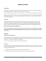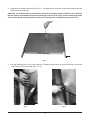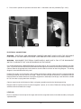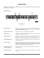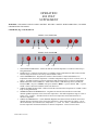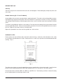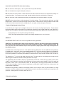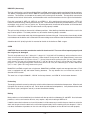
1
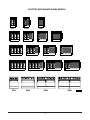
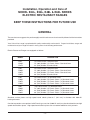
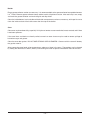
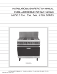
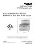
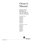
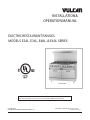
INSTALLATION &
OPERATION MANUAL
ELECTRIC RESTAURANT RANGES
MODELS E24L, E36L, E48L, & E60L SERIES
Model E48L
For additional information on Vulcan-Hart or to locate an authorized parts
and service provider in your area, visit our website at www.vulcanhart.com
VULCAN-HART
DIVISION OF ITW FOOD EQUIPMENT GROUP, LLC
P.O. BOX 696, LOUISVILLE, KY 40201-0696
TEL. (502) 778-2791
FORM 30968 Rev. B (04-08)
The following models have been discontinued and are no longer available:
E24SL
E24FL
E36XL
E48L
E48SL
E48FL
–2–
E48XL
E60SL
TABLE OF CONTENTS
ELECTRIC RESTAURANT RANGE MODELS . . . . . . . . . . . . . . . . . . . . . . . . . . . . . . . . . . . . . . . . . . . . . . . . . 4
GENERAL . . . . . . . . . . . . . . . . . . . . . . . . . . . . . . . . . . . . . . . . . . . . . . . . . . . . . . . . . . . . . . . . . . . . . . . . . . . . . . 5
INSTALLATION . . . . . . . . . . . . . . . . . . . . . . . . . . . . . . . . . . . . . . . . . . . . . . . . . . . . . . . . . . . . . . . . . . . . . . . . . 6
Unpacking . . . . . . . . . . . . . . . . . . . . . . . . . . . . . . . . . . . . . . . . . . . . . . . . . . . . . . . . . . . . . . . . . . . . . . . 6
Location . . . . . . . . . . . . . . . . . . . . . . . . . . . . . . . . . . . . . . . . . . . . . . . . . . . . . . . . . . . . . . . . . . . . . . . . . 6
Installation Codes and Standards . . . . . . . . . . . . . . . . . . . . . . . . . . . . . . . . . . . . . . . . . . . . . . . . . . . . 6
Assembly . . . . . . . . . . . . . . . . . . . . . . . . . . . . . . . . . . . . . . . . . . . . . . . . . . . . . . . . . . . . . . . . . . . . . . . . 6
Electrical Connections . . . . . . . . . . . . . . . . . . . . . . . . . . . . . . . . . . . . . . . . . . . . . . . . . . . . . . . . . . . . . 8
Leveling . . . . . . . . . . . . . . . . . . . . . . . . . . . . . . . . . . . . . . . . . . . . . . . . . . . . . . . . . . . . . . . . . . . . . . . . . 8
OPERATION . . . . . . . . . . . . . . . . . . . . . . . . . . . . . . . . . . . . . . . . . . . . . . . . . . . . . . . . . . . . . . . . . . . . . . . . . . . 9
Controls . . . . . . . . . . . . . . . . . . . . . . . . . . . . . . . . . . . . . . . . . . . . . . . . . . . . . . . . . . . . . . . . . . . . . . . . . 9
Before First Use . . . . . . . . . . . . . . . . . . . . . . . . . . . . . . . . . . . . . . . . . . . . . . . . . . . . . . . . . . . . . . . . . 10
Surface Plates . . . . . . . . . . . . . . . . . . . . . . . . . . . . . . . . . . . . . . . . . . . . . . . . . . . . . . . . . . . . . . . . . . . 10
Griddle . . . . . . . . . . . . . . . . . . . . . . . . . . . . . . . . . . . . . . . . . . . . . . . . . . . . . . . . . . . . . . . . . . . . . . . . . 11
Broiler (Accessory) . . . . . . . . . . . . . . . . . . . . . . . . . . . . . . . . . . . . . . . . . . . . . . . . . . . . . . . . . . . . . . . 12
Oven . . . . . . . . . . . . . . . . . . . . . . . . . . . . . . . . . . . . . . . . . . . . . . . . . . . . . . . . . . . . . . . . . . . . . . . . . . 12
Power Outage . . . . . . . . . . . . . . . . . . . . . . . . . . . . . . . . . . . . . . . . . . . . . . . . . . . . . . . . . . . . . . . . . . . 13
Cleaning . . . . . . . . . . . . . . . . . . . . . . . . . . . . . . . . . . . . . . . . . . . . . . . . . . . . . . . . . . . . . . . . . . . . . . . . 13
MAINTENANCE . . . . . . . . . . . . . . . . . . . . . . . . . . . . . . . . . . . . . . . . . . . . . . . . . . . . . . . . . . . . . . . . . . . . . . . . 15
Service and Parts Information . . . . . . . . . . . . . . . . . . . . . . . . . . . . . . . . . . . . . . . . . . . . . . . . . . . . . . 15
–3–
ELECTRIC RESTAURANT RANGE MODELS
E24L
E24SL
E24FL
E36SL
E36L
E48SL
E48L
E36XL
E48FL
E60SL
E60L
E24L
E36FL
E36L
E60FL
E48L
–4–
E48XL
E60XL
E60L
PL-51578
Installation, Operation and Care of
MODEL E24L, E36L, E48L & E60L SERIES
ELECTRIC RESTAURANT RANGES
KEEP THESE INSTRUCTIONS FOR FUTURE USE
GENERAL
The manufacturer suggests that you thoroughly read this entire manual and carefully follow all of the instructions
provided.
Your Vulcan-Hart range is produced with quality workmanship and material. Proper installation, usage and
maintenance of your range will result in many years of satisfactory performance.
Electric Restaurant Ranges are equipped as follows:
MODEL
DESCRIPTION
E24L
E24SL
E24FL
(4) French Plates / Standard Oven
12" (305) Griddle / (2) French Plates / Standard Oven
24" (610) Griddle / Standard Oven
E36L
E36SL
E36FL
E36XL
(6) French Plates / Standard Oven
12" (305) Griddle / (4) French Plates / Standard Oven
24" (610) Griddle / (2) French Plates / Standard Oven
36" (914) Griddle / Standard Oven
E48L
E48SL
E48FL
E48XL
(8) French Plates / (2) Standard Ovens
12" (305) Griddle / (6) French Plates / (2) Standard Ovens
24" (610) Griddle / (4) French Plates / (2) Standard Ovens
36" (914) Griddle / (2) French Plates / (2) Standard Ovens
E60L
E60SL
E60FL
E60XL
(10) French Plates / (2) Standard Ovens
12" (305) Griddle / (8) French Plates / (2) Standard Ovens
24" (610) Griddle / (6) French Plates / (2) Standard Ovens
36" (914) Griddle / (4) French Plates / (2) Standard Ovens
Standard surface plates are high speed round tubular plates 91/2" (241 mm) in diameter with 2000 W.
heating elements.
One hot top section or two optional solid French-type cast iron (2000 W. each) may be substituted for two high
speed round tubular plates. High-speed round tubular plates are not recommended for stock pot work.
–5–
INSTALLATION
UNPACKING
Immediately after unpacking, check for possible shipping damage. If the range is found to be damaged, save
the packaging material and contact the carrier within 15 days of delivery.
Remove all shipping wire, wood blocking, and accessories. Uncrate the high shelf, backguards and/or broiler.
Before installing, verify that the electrical service agrees with the specifications on the rating plate located behind
the kick panel on the left side. If the supply and equipment requirements do not agree, contact your dealer or
Vulcan-Hart immediately.
LOCATION
The installation location must allow adequate clearance for servicing and proper operation. A minimum front
clearance of 40" (1016 mm) is required. 0" sides and rear clearance from combustible and non-combustible
construction is required except when hot top sections are incorporated. Ranges incorporating hot top sections
require a 0" sides and rear clearance form non-combustible construction and 6" from combustible construction.
INSTALLATION CODES AND STANDARDS
Your Vulcan range must be installed in accordance with state and local codes, or in the absence of local codes,
with National Electrical Code ANSI/NFPA-70 (latest edition) available from The National Fire Protection
Association, Batterymarch Park, Quincy, MA 02269. In Canada refer to Canadian electrical code C22.1 Part 1
(latest edition).
ASSEMBLY
Model ESB Broiler/Backguard
In E36L and E60L Series, slide the legs of the broiler inside the channels provided in the back of the range (in
E60L Series, the broiler is mounted between the center and the right-hand channel), until the two holes on each
side line up. Fasten with the bolts and nuts provided.
In a similar way, mount the backguard to the left side of the broiler.
High Shelf
The high shelf for this range is shipped knocked down and is included in the range crate. The splasher back and
heat shield are bolted together and shipped attached to the rear of the range. The hardware required to assemble
the shelf is packed in the oven.
1. Remove the splasher back and heat shield from the rear of the range.
2. Remove the heat shield from the splasher back by removing two sheet metal screws.
–6–
3. Assemble heat shield to splasher back (Fig. 1). Top edge of heat shield must be placed inside the rear top
flange of the splasher back.
CAUTION: It is essential that the heat shield in the back of the high shelf be installed in such a way that
the bent section at the bottom be inward, touching the rear wall of the range, thereby allowing the stack
action of the double wall back splasher to draw air through the area below the top surface units.
PL-40459
Fig. 1
4. With top cooking plates in their normal position, assemble splasher back to range and fasten in place with
1
/4-20 screws and nuts provided (Fig's. 2 & 3) .
PL-40461
PL-40460
Fig. 2
Fig. 3
–7–
5. Place shelf in position on splasher and fasten with 1/ 4-20 screws and nuts provided (Fig's. 4 & 5) .
PL-40463
PL-40462
Fig. 4
Fig. 5
ELECTRICAL CONNECTIONS
WARNING: ELECTRICAL AND GROUNDING CONNECTIONS MUST COMPLY WITH THE APPLICABLE
PORTIONS OF THE NATIONAL ELECTRICAL CODE AND/OR OTHER LOCAL ELECTRICAL CODES.
WARNING: DISCONNECT ELECTRICAL POWER SUPPLY AND PLACE A TAG AT THE DISCONNECT
SWITCH TO INDICATE THAT YOU ARE WORKING ON THE CIRCUIT.
On ranges equipped with a Model ESB Broiler, bring the leads A1, A2, B1 and B2 (on 240 volt models, the leads
are X, Y, N) which are connected to the broiler down and through the burner box to the switch panel compartment.
Connect them to the appropriate circuit breaker or terminal block as shown on the wiring diagram. The wiring
diagram is located behind the kick panel.
Position the range in its final location. Bring conduit containing the proper supply wire to the range through the
knockout located on the left side of the range. Select the size and type of field wire in accordance with the
National Electrical Code suitable for carrying the equipment's rated amps and voltage. Use field wires suitable
for 75°C on units carrying more than 80 amps.
Connect supply leads to field terminal block and green grounding lead to the labeled ground lug.
Ranges wired for 3-phase service may be changed to 1-phase, or vice versa. Refer to the wiring diagram and
schematic decal attached to the range.
LEVELING
Place a carpenter's level on top of the range and level the range front-to-back and side-to-side by turning the
adjustable feet.
–8–
OPERATION
WARNING: THE RANGE AND ITS PARTS ARE HOT. BE VERY CAREFUL WHEN OPERATING, CLEANING
OR SERVICING THE RANGE.
CONTROLS (Fig. 6)
Oven
Indicator
Light
Element
Control
Knobs
Oven
Thermostat
Oven
Infinite
Switch
Element
Indicator
Light
PL-40464-1
Model E36L Shown
Fig. 6
Element Controls
— Infinite load switches that control and maintain heat to the surface plates.
The controls are arranged in pairs; the left knob controls the front plate and
the right knob controls the rear plate.
Element Indicator Lights
— When lit, indicate heat is being supplied to the element.
Hot Top Switch
— (Not shown.) A 4-heat switch (HI, MED HI, MED LO, LO) controls and
maintains heat to the hot top section.
Griddle Thermostat
— (Not shown.) Regulates the amount of heat needed to maintain the set
temperature. Each 12" (305 mm) section of the griddle has its own
thermostat with a temperature range of 150°F (65°C) to 550°F (288°C).
Griddle Indicator Light
— (Not shown.) Will be lit until the selected temperature is reached or when it
is being maintained.
Oven Thermostat
— Regulates the amount of heat needed to control and maintain oven
temperature around the desired set temperature. The temperature range is
from 150°F (65°C) to 550°F (288°C). Turn dial counterclockwise to increase
temperature and clockwise to decrease temperature.
Infinite Switch for Oven
Top Heating Element
— Provides directional heat control. Adjust as needed for the amount of
top heat required.
Oven Indicator Light
— Will be lit until the selected temperature is reached or when it is being
maintained.
–9–
OPERATION
480 VOLT
SUPPLEMENT
WARNING: THE RANGE AND IT’S PARTS ARE HOT. BE VERY CAREFUL WHEN OPERATING, CLEANING
OR SERVICING THE RANGE.
CONTROLS (Fig. 6A & 6B) 480 volt
MODEL E36L SHOWN 6A
1
2
3
4
4
MODEL E36X SHOWN 6B
5
1.
2.
3.
4.
5.
6.
7.
6
5
6
OVEN INDICATOR LIGHT – Will be lit until the selected temperature is reached or when temp. is
being maintained.
PANEL PLUG – Fills hole in panel where oven Infinite switch would mount on 208 & 240 volt units.
480 Volt ranges do not have an oven top element infinite control.
OVEN THERMOSTAT – Regulates the amount of heat needed to control and maintain oven
temperature at the selected set temperature. Selectable temperature range is 150°F. to 550°F. (65°C. to
288°C.) Turn dial clockwise to increase temperature and counterclockwise to decrease temperature.
FRENCH PLATE 3 HEAT SWITCH – Each switch controls a 2000 Watt top surface (round) unit.
Positions OFF = No power. HIGH = Full power 2000 W. MED = ½ power 1000 W. LO = ¼ power
500 W. Select as desired to maintain surface unit heat level.
SURFACE INDICATOR LIGHT - Will be lit until the selected surface temperature is reached or when
temp. is being maintained.
GRIDDLE SURFACE THERMOSTAT – Regulates the amount of heat needed to control and
maintain griddle temperature at the selected set temperature. Selectable temperature range is 150°F. to
550°F. (65°C. to 288°C.) Turn dial clockwise to increase temperature and counterclockwise to
decrease temperature.
SURFACE THERMOSTAT – (NOT SHOWN) Regulates the amount of heat needed to control and
maintain hot top temperature at the selected set temperature. Select temperature by setting “1 to 10”
dial for minimum (1) to maximum (10) temperature. (1 ≈ 350°F. 10≈ 750°F.) Turn dial clockwise to
increase temperature and counterclockwise to decrease temperature. Also uses item 5 above.
F30968-S REV B (04-08)
9A
BEFORE FIRST USE
Cleaning
Clean the range and all accessories with water and a mild detergent. Rinse thoroughly and wipe dry with a soft
clean cloth.
Griddle Seasoning (SL, FL and XL Models)
A new griddle surface must be seasoned to do a good cooking job. The metal surface of the griddle is porous.
Food tends to get trapped in these pores and stick; therefore, it is important to "season" or "fill up" these pores
with cooking oil before cooking. Seasoning gives the surface a slick, hard finish from which the food will release
easily.
To season, heat griddle top section at a low setting. Pour one ounce of cooking oil per square foot of surface
over the griddle top section. With an insulated cloth, spread the oil over the entire griddle surface to create a
thin film. Wipe off any excess oil with an insulated cloth.
Repeat this procedure 2 to 3 times until the griddle has a slick surface.
SURFACE PLATES
French plates are most efficient when used with utensils having a maximum inside diameter of 10" (254)
or a minimum inside diameter of 9" (229). Stock pots of 9, 12 and 16 qt. capacities are recommended for bulk
cooking. (Fig. 7)
Fig. 7
The solid surface plates are rated for 2000 Watts and are controlled by an infinite heat switch. A solid surface
plate will reach cooking temperature from room temperature in 5 to 7 minutes at a HI switch setting.
Each control knob is marked HI, MED, LO, MED-LO, and VERY-LO. The HI setting is full heat. Use the HI setting
to start cooking quickly and to bring water to a boil.
– 10 –
Some DO'S and DO NOT'S of Surface Cooking
DO use utensils to fit the tops (9" to 10" [229 to 254 mm] inside diameter).
DO use flat-bottomed, straight-sided pots and pans.
DO use covers for stock pot work. Water will boil much sooner and much less heat is required for cooking in a
covered container. Less water may be used, thereby retaining vitamins and minerals in the food.
DO turn off plates a few minutes before cooking is completed to use the heat stored in the plate.
DO NOT allow surface plates to idle unloaded at HI switch settings. The surface plates will reach very high
temperatures, and this can cause the casting to warp or dome. Plates idled at a setting of MED-LO and turned
to HI when loaded, will perform bulk cooking jobs just as rapidly, without damage to the plates.
* Optional High-Speed Surface Plates
If so ordered, your range may be equipped with one or more heavy duty high-speed plates. These optional
high-speed tubular-type surface plates are available for use with fry pans and stock pots up to 10" (254 mm) in
diameter or 16 qt. capacity. While the surface plate cooking information above applies, there are some differences:
High-speed plates are for quick heating and cooking.
Heavy duty high-speed plates will preheat to cooking temperatures in 2 to 5 minutes.
GRIDDLE
See BEFORE FIRST USE in this manual for griddle seasoning procedure.
CAUTION: This griddle plate is steel, but the surface is relatively soft and can be scored or dented by
the careless use of a spatula or scraper. Be careful not to dent, scratch, or gouge the plate surface. Do
not try to knock off loose food that may be on the spatula by tapping the corner edge of the spatula on
the griddle surface.
All models with a suffix of SL have a 12" x 24" (305 x 610 mm) griddle which has one 3400 W. heating element.
All models with a suffix of FL have a large double griddle (24" x 24" [610 x 610 mm]) which has two 3400 W.
heating elements. Models E36XL, E48XL and E60XL have a 36" griddle with three 3400 W. heating elements.
Each heating element is individually controlled by a thermostat with a range of 150°F to 550°F (66°C to 288°C).
The griddle has a 7/8" (22 mm) high edge around 3 sides. The right side has a drip edge for drainage into the
slide-out grease collector mounted on the right side of the range.
The griddle will preheat to 400°F (204°C) in approximately 10 minutes, or will come up to 400°F (204°C) from
a 300°F (149°C) setting in 3 minutes. During breakfast, you may set one control at 300°F (149°C) for eggs and
the other at 375°F (191°C) for pancakes, bacon, etc. During lunch, you might use the whole area at 350°F
(177°C) for hamburgers, or set one side for hamburgers and the other at 400°F (204°C) for minute steaks and
grilled cheese sandwiches.
Between serving periods, foods that take longer to cook, such as soup or stew, may be simmered in a large
container set on the griddle surface. If no grilled items are to be served, pans of food may be kept hot on the
griddle at a setting of 150°F to 250°F (66°C to 121°C).
* Discontinued Option
– 11 –
BROILER (Accessory)
The high-shelf broiler is available on Models E36L and E60L except those models supplied with hot top sections.
The broiler is equipped with 2 tubular 3000 W. heating elements independently controlled by two infinite heat
switches. The switches are located on the switch panel at the right of the broiler. The top switch controls the
element for the left half of the broiler, and the bottom switch controls the element for the right half of the broiler.
Each dial is marked HI, MED, LO, MED-LO, and VERY-LO. HI is used for quick searing of steaks. VERY-LO
is best suited for warming, melting cheese on pie, etc. The intermediate positions provide flexibility for a variety
of products, such as fish, liver, au gratins, etc. By setting the switch for one-half of the broiler at HI and the other
from MED to VERY-LO, a variety of broiler foods can be properly handled.
The grid and drip shield can be used in 3 different positions. Most broiling should be done with the rack in the
top or center position. The lower position may be used for browning deep casseroles.
The rack has a removable metal drip shield supported at the front of the grid. Grease drains from the drip shield
into the bottom of the broiler and is collected in the removable grease collector under the left bottom of the broiler.
A double-deck 24" (610) high shelf is mounted to the left of the broiler on E60L ranges.
OVEN
CAUTION: Never cover the oven deck or rack with aluminum foil. The oven will not operate properly and
the range may be damaged.
The fully insulated oven is 26 1/4" wide x 22 1/2" deep x 14 1/2" high (667 x 572 x 368 mm), with an effective rack or
deck area 25" wide x 22" deep (635 x 559 mm). Bake sheets or roast pans 20" x 22" (508 x 559 mm) (restaurant
size) are recommended. Place pans at least 1/ 2" (13 mm) from the walls and back and 2" (51 mm) from the door
when closed. The oven will accommodate 6" to 7" (152 to 178 mm) or 5" to 8" (127 to 203 mm) layer cake or
pie pans. It is not designed to perform satisfactorily with an 18" x 26" (457 x 660 mm) pan, or with 2-200 series
(12 3/ 4" x 20 3/ 4" [329 x 527 mm]) food service pans.
Model E24L and E36L ranges have a single oven; Model E48L and E60L ranges have two separate ovens. Each
oven is equipped with top and bottom heating elements. The top element has an infinite heat switch for
directional heat control.
The oven has an input of 5000 W., 1250 W. for the top element, and 3750 W. for the bottom element.
Preheating
Thoroughly preheat the oven by setting the switch and the thermostat to the desired temperature. When the red
light goes out, the oven is ready for use. For full loads and delicate baked products, it may be desirable to allow
the oven to cycle (red light on and off) a second time before loading.
Baking
Most products can be baked directly on the deck with the top switch set between LO and MED. Hard-to-brown
products, such as corn bread or biscuits, may require a top switch setting of MED to HI.
If both the oven deck and oven rack are fully loaded, it will be necessary to switch the pans from the rack to the
deck and the pans from the deck to the rack when approximately half the cooking time has elapsed. If this is
not done, the bottom of products on the rack and the top of the product on the deck will not cook properly.
– 12 –
Roasting
Place meat on a rack in an open pan with sides sufficiently high to retain the drippings. Roasting may be done
on the oven rack or the deck. For best results, roast at the low temperatures of 200°F (93°C) to 325°F (163°C)
recommended by the Department of Agriculture and the American Meat Institute. Most meats may be roasted
with the infinite heat switch set at HI. If heavy browning on poultry is not desired, the switch should be set
between MED-LO and VERY-LO.
The top oven element is not suitable for broiling.
POWER OUTAGE
If a power outage occurs, the range will automatically shut down. When power is restored, the range will
automatically resume normal functions after it has preheated for 5 minutes. If the range is left unattended during the
power outage, turn all control knobs/switches OFF. When power is restored, turn desired control knobs/switches
back ON. The unit will be preheated in 5 minutes and normal cooking operations can be resumed.
CLEANING
WARNING: DISCONNECT ELECTRICAL POWER SUPPLY BEFORE CLEANING.
Do not use Dawn dish detergent to clean the exterior or interior components of the range.
Do not use scouring powder. It is extremely difficult to remove completely. It can build up accumulations that
will damage the range.
Clean all parts of the range and the oven with a soft cloth and warm water and detergent. Rinse thoroughly and
wipe dry with a soft clean cloth.
High-Speed Surface Plates
High-speed surface plates may be raised for cleaning. CAUTION: Replace surface plates in their original
position in the plate support. Twisting or rotating of the surface plates can damage wiring.
Remove the drip tray under the high-speed surface plates. After cleaning replace in the same positions.
Griddle
Scrape the griddle with a spatula after each use. Daily, or more often if necessary, empty and wipe out the grease
collector. Weekly, or more often if necessary, thoroughly clean the griddle surface. You may use a griddle screen
or stone with a little grease, rubbing with the grain of the metal while it is still warm, or use water and detergent
with a steel brush. The detergent must be thoroughly removed. After each thorough cleaning, the griddle must
be reseasoned (see BEFORE FIRST USE in this manual).
Avoid build-up of caked grease under the drip edge and around the outside edges of the griddle.
If the griddle is to be shut down for an extended period, put a heavy coat of grease over the griddle plate.
– 13 –
Broiler
Empty grease collector as often as necessary. It is recommended that the grease collector be emptied whenever
it is 3/4 filled. Remove grease collector slowly and be careful of liquid wave action. After each day's use, empty
and wash the grease collector and wash the grid and drip shield.
Clean the inside bottom, back and sides of the broiler compartment as often as necessary, with special care to
clean the inside surface of the baffle across the front top of the broiler.
Oven
Clean oven and oven door daily, especially if fruit pies or tomato sauces were baked, meats roasted, and if there
have been spillovers.
If the oven liners and decks are heavily soiled, ammonia or oven cleaner may be used to remove spillage of
burned on sugar and grease.
Clean the oven door gasket. DO NOT USE STRONG OVEN CLEANERS. Cleaners of this nature will destroy
the gasket material.
After processing some foods at low temperatures, odors may linger in the oven. These odors may be cleared
by setting the thermostat at 500°F (260°C) and allowing the oven to operate unloaded for 30 to 45 minutes.
– 14 –
MAINTENANCE
WARNING: THE RANGE AND ITS PARTS ARE HOT. BE VERY CAREFUL WHEN OPERATING, CLEANING
OR SERVICING THE RANGE.
SERVICE AND PARTS INFORMATION
To obtain service and parts information concerning this range, contact the Vulcan-Hart Service Department in
your area or Service Department at the address or phone number shown on the front cover of this manual.
– 15 –
FORM 30968 Rev. A (02-04)
– 16 –
PRINTED IN U.S.A.