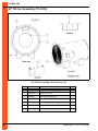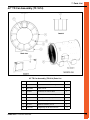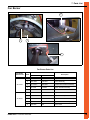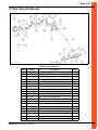
1
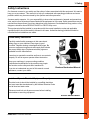
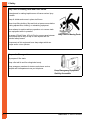
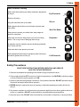
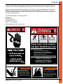
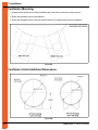
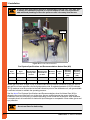
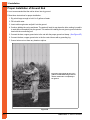
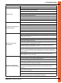
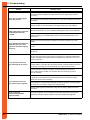
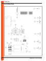
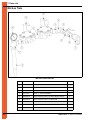
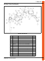
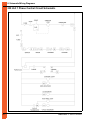
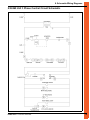
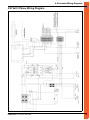
Farm Fans Combined Fan/Heater
Installation and Operation
PNEG-1523
Date: 02-11-11
PNEG-1523
2
PNEG-1523 FTF Series Fan/Heater
Table of Contents
Contents
Chapter 1 Safety .....................................................................................................................................................4
Safety Guidelines .................................................................................................................................. 4
Safety Instructions ................................................................................................................................. 5
Safety Precautions ................................................................................................................................ 7
Chapter 2 Decals ....................................................................................................................................................9
Chapter 3 Installation ..........................................................................................................................................10
Fan/Heater Mounting .......................................................................................................................... 10
Fan/Heater Unit Installation Dimensions ............................................................................................. 10
Duct and Drying Fan Pad Optional ..................................................................................................... 11
Electrical Load Information .................................................................................................................. 13
Power Supply ...................................................................................................................................... 13
Transformer and Wiring Voltage Drop ................................................................................................ 13
Machine to Earth Grounding ............................................................................................................... 13
Proper Installation of Ground Rod ....................................................................................................... 14
Main Power Schematic ....................................................................................................................... 15
Thermostat Connections ..................................................................................................................... 16
Chapter 4 Operation ............................................................................................................................................17
Fan Operation ..................................................................................................................................... 17
Heater Operation ................................................................................................................................. 17
Chapter 5 Service .................................................................................................................................................19
Seasonal Inspection and Service ........................................................................................................ 19
Chapter 6 Troubleshooting .................................................................................................................................21
Chapter 7 Parts List .............................................................................................................................................23
Control Box Parts ................................................................................................................................ 24
36" TD Can Assembly (TF-1613) ........................................................................................................ 26
42" TD Can Assembly (TF-1614) ........................................................................................................ 27
Fan Motor, Motor Mount and Fan Blade ............................................................................................. 28
Fan Burner .......................................................................................................................................... 29
LP Gas Train ....................................................................................................................................... 30
NG Gas Train ...................................................................................................................................... 32
Chapter 8 Schematic/Wiring Diagrams ..............................................................................................................34
230 Volt 1 Phase Control Circuit Schematic ....................................................................................... 34
230/460 Volt 3 Phase Control Circuit Schematic ................................................................................ 35
230 Volt 1 Phase Wiring Diagram ....................................................................................................... 36
230 Volt 3 Phase Wiring Diagram ....................................................................................................... 37
460 Volt 3 Phase Wiring Diagram ....................................................................................................... 38
Chapter 9 Warranty ..............................................................................................................................................39
PNEG-1523 FTF Series Fan/Heater
3
1. Safety
Safety Guidelines
This manual contains information that is important for you, the owner/operator, to know and understand.
This information relates to protecting personal safety and preventing equipment problems. It is the
responsibility of the owner/operator to inform anyone operating or working in the area of this equipment
of these safety guidelines. To help you recognize this information, we use the symbols that are defined
below. Please read the manual and pay attention to these sections. Failure to read this manual and its
safety instructions is a misuse of the equipment and may lead to serious injury or death.
This is the safety alert symbol. It is used to alert you
to potential personal injury hazards. Obey all safety
messages that follow this symbol to avoid possible
injury or death.
DANGER
WARNING
4
DANGER indicates a hazardous situation which, if not
avoided, will result in death or serious injury.
WARNING indicates a hazardous situation which, if not
avoided, could result in death or serious injury.
CAUTION
CAUTION, used with the safety alert symbol, indicates a
hazardous situation which, if not avoided, could result in
minor or moderate injury.
NOTICE
NOTICE is used to address practices not related to
personal injury.
PNEG-1523 FTF Series Fan/Heater
1. Safety
Safety Instructions
Our foremost concern is your safety and the safety of others associated with this equipment. We want to
keep you as a customer. This manual is to help you understand safe operating procedures and some
problems which may be encountered by the operator and other personnel.
As owner and/or operator, it is your responsibility to know what requirements, hazards and precautions
exist, and to inform all personnel associated with the equipment or in the area. Safety precautions may be
required from the personnel. Avoid any alterations to the equipment. Such alterations may produce a very
dangerous situation where SERIOUS INJURY or DEATH may occur.
This equipment shall be installed in accordance with the current installation codes and applicable
regulations which should be carefully followed in all cases. Authorities having jurisdiction should be
consulted before installations are made.
Follow Safety Instructions
Carefully read all safety messages in this manual and
safety signs on your machine. Keep signs in good
condition. Replace missing or damaged safety signs. Be
sure new equipment components and repair parts include
the current safety signs. Replacement safety signs are
available from the manufacturer.
Learn how to operate the machine and how to use controls
properly. Do not let anyone operate without instruction.
Keep your machinery in proper working condition.
Unauthorized modifications to the machine may impair
the function and/or safety and affect machine life.
Read and Understand Manual
If you do not understand any part of this manual or need
assistance, contact your dealer.
Install and Operate Electrical Equipment Properly
Electrical controls should be installed by a qualified electrician
and must meet the standards set by the National Electrical Code
and all local and state codes.
Disconnect and lock out all power sources before installing
wires/cables or servicing equipment.
Electric Shock Hazard
PNEG-1523 FTF Series Fan/Heater
5
1. Safety
Stay Clear of Rotating Parts and Pinch Points
Entanglement in rotating impeller arms will cause serious injury
or death.
Keep all shields and covers in place at all times.
Wear close fitting clothing. Stop and lock out power source before
making adjustments, cleaning, or maintaining equipment.
Never attempt to assist machinery operation or to remove trash
from equipment while in operation.
Be aware of Pinch Points. A Pinch Point is a narrow area between
two surfaces that is likely to trap or catch objects and is a
potential safety hazard.
Stay Clear of Moving Parts
Components of this equipment have sharp edges which can
scrape and/or cut an operator.
Prepare for Emergencies
Be prepared if fire starts.
Keep a first aid kit and fire extinguisher handy.
Keep emergency numbers for doctors, ambulance service,
hospital and fire department near your telephone.
Keep Emergency Equipment
Quickly Accessible
6
PNEG-1523 FTF Series Fan/Heater
1. Safety
Wear Protective Clothing
Wear close fitting clothing and safety equipment appropriate
to the job.
Eye Protection
Remove all jewelry.
Long hair should be tied up and back.
Gloves
Safety glasses should be worn at all times to protect eyes
from debris.
Steel Toe Boots
Wear gloves to protect your hands from sharp edges on
plastic or steel parts.
Wear steel toe boots to help protect your feet from falling
debris. Tuck in any loose or dangling shoe strings.
Respirator
A respirator may be needed to prevent breathing potentially
toxic fumes and dust.
Hard Hat
Wear hard hat to help protect your head.
Wear appropriate fall protection equipment when working at
elevations greater than six feet (6').
Fall Protection
Safety Precautions
READ THESE INSTRUCTIONS BEFORE OPERATION AND SERVICE
SAVE FOR FUTURE REFERENCE
1. Read and understand the operating manual before trying to operate the dryer.
2. Power supply should be OFF for service of electrical components. Use CAUTION in checking voltage
or other procedures requiring power to be ON.
3. Check for gas leaks at all gas pipe connections. If any leaks are detected, DO NOT operate the dryer.
Shut down and repair before further operation.
4. NEVER attempt to operate the dryer by jumping or otherwise bypassing any safety devices on
the unit.
5. Set pressure regulator to avoid excessive gas pressure applied to burner during ignition and when
burner is in operation. DO NOT exceed maximum recommended drying temperature.
6. Keep the dryer clean. DO NOT allow fine material to accumulate in the plenum or drying chamber.
PNEG-1523 FTF Series Fan/Heater
7
1. Safety
Safety Precautions (Continued)
7. Use CAUTION in working around high speed fans, gas burners, augers and auxiliary conveyors
which can START AUTOMATICALLY.
8. DO NOT operate in any area where combustible material will be drawn into the fan.
9. BEFORE attempting to remove and re-install any propeller, make certain to read the recommended
procedure listed within the servicing section on Page 19 of the manual.
10. Clean grain is easier to dry. Fine material increases resistance to airflow and requires removal of
extra moisture.
Proper Use of Product
This product is intended for the use of drying small grains only. Any other use is a misuse of the product.
This product has sharp edges. These sharp edges may cause serious injury. To avoid injury handle sharp
edges with caution and use proper protective clothing and equipment at all times.
Guards are removed for illustration purposes only. All guards must be in place before and
during operation.
Use Caution in the Operation of this Equipment
This dryer is designed and manufactured with operator safety in mind. However, the very nature of a grain
dryer having a gas burner, high voltage electrical equipment and high speed rotating parts, presents
hazards to personnel which can not be completely safeguarded against without interfering with the
efficient operation of the dryer and reasonable access to its components.
Use extreme caution in working around high speed fans, gas-fired heaters, augers and auxiliary
conveyors, which may start without warning when the dryer is operating on automatic control.
CAUTION
Keep the dryer clean. Do not allow fine material to accumulate in the plenum
chamber or surrounding the outside of the dryer.
Continued safe, dependable operation of automatic equipment depends, to a great degree, upon
the owner. For a safe and dependable drying system, follow the recommendations within this manual and
make it a practice to regularly inspect the unit for any developing problems or unsafe conditions.
Take special note of the Safety Precautions on Page 7 before attempting to operate the dryer.
8
PNEG-1523 FTF Series Fan/Heater
2. Decals
The GSI recommends contacting your local power company and having a representative survey the
installation so the wiring is compatible with their system and adequate power is supplied to the unit.
Safety decals should be read and understood by all people in the grain handling area. The rotating
blade, fire warning decals and voltage danger decal must be displayed on the fan can. The decal
DC-GBC-1A should be present on the inside bin door cover of the 2 ring door, 24" porthole door cover
and the roof manway cover.
If a decal is damaged or is missing contact:
GSI Decals
1004 E. Illinois St.
Assumption, IL. 62510
Phone: 1-217-226-4421
A free replacement will be sent to you.
Rotating flighting will
kill or dismember.
Flowing material will
trap and suffocate.
Crusted material will
collapse and suffocate.
Keep clear of all augers.
DO NOT ENTER this bin!
If you must enter the bin:
1. Shut off and lock out all power.
2. Use a safety harness and safety line.
3. Station another person outside the bin.
4. Avoid the center of the bin.
5. Wear proper breathing equipment or respirator.
Failure to heed these
warnings will result in
serious injury or death.
DC-1224
DC-GBC-1A
WARNING
Stay clear of rotating
blade. Blade could start
automatically. Can cause
serious injury. Disconnect
power before servicing.
DC-1225
PNEG-1523 FTF Series Fan/Heater
WARNING
Flame and pressure beyond
door can cause serious
injury. Do not operate with
service door removed. Keep
head and hands clear.
DC-1227
9
3. Installation
Fan/Heater Mounting
1. Inspect the fan platform for proper installation per instructions in the bin erection manual.
2. Raise the fan/heater units to the platform.
3. Mount the fan/heater units to the bin entrance sheets. Fan legs should set on the platform.
Figure 3A
Fan/Heater Unit Installation Dimensions
Figure 3B
10
PNEG-1523 FTF Series Fan/Heater
3. Installation
Duct and Drying Fan Pad Optional
Placement of the duct fan pad: GSI top dry duct system only.
Refer to Figure 3C to determine the duct pad size. The top of this pad should be level with the top of the
bin’s foundation. Recommended pad thickness is 4" minimum.
Figure 3C
Fuel System Specifications and Recommendations Liquid Propane (LP)
Dryer Fan
Size
Dryer
Horsepower
Maximum Heat
Capacity BTU
per Hour
Maximum Fuel
Flow Gallons
per Hour
Minimum
Line Size
Orifice
Size
Minimum
Operating
Pressure
(PSI)
Maximum
Operating
Pressure
(PSI)
36"
15
4-1/2 Million
54
1/2"
21/64"
1 lb.
15 lbs.
42"
30
8-3/4 Million
95
1/2"
7/16"
1 lb.
15 lbs.
These fan/heater units have internal vaporizers and they are designed to operate on liquid draw from the
supply tank. Avoid using propane supply tanks that have been used for vapor draw for long periods of time.
When using liquid draw systems any moisture that may be present in tanks or lines may freeze when the
system is used in cold weather. To avoid this situation, purge the system with methanol. Also do not make
any line size changes from the supply tank to the burner. This can cause premature vaporizing of the fuel
and will result in burner failure.
Do not use tanks which have been used for ammonia or fertilizer solutions. These
NOTICE substances are extremely corrosive and will damage fuel supply and burner parts.
Because the vaporizer coil may need to be adjusted during operation flexible hose suitable for LP should
be used for the final field connection. See the above Fuel Systems Specifications and Recommendations
chart for Liquid Propane (LP) to determine the correct size line to run from the tank to the dryer. Installation
and maintenance should be performed only by qualified personnel. Installation must meet the requirements
and provisions of NFPA #54, NFPA #58, DOT, ANSI and all applicable federal, state, provincial and local
standards, codes, regulations and laws. After installation is complete, check all connections for leaks with
liquid detergent or comparable. Wear rubber gloves and eye protection. Avoid contact with liquid propane.
Do not use flame for leak testing.
WARNING
PNEG-1523 FTF Series Fan/Heater
11
3. Installation
WARNING
Pressure relief valve should always be pointed away from the user. If the pipe train
is altered for installation purposes it is up the installer or end user to position or
add additional plumbing to direct the pressure relief valve away from the user.
Pressure
relief valve
Figure 3D LP Line Field Connection
Fuel System Specifications and Recommendations Natural Gas (NG)
Dryer
Fan Size
Dryer
Horsepower
Maximum Heat
Capacity BTU
per Hour
Maximum Fuel
Flow Cubic Ft.
per Hour
Minimum
Line Size
Orifice
Size
Minimum
Operating
Pressure
(PSI)
Maximum
Operating
Pressure
(PSI)
36"
15
5 Million
5280
2"
1/2"
1 lb.
7 lbs.
42"
30
9 Million
9536
2"
43/64"
1 lb.
7 lbs.
Natural gas units have a larger orifice to accommodate lower pressures sometimes found with natural
gas and do not have vaporizer coils like liquid propane units. A regulated pressure of 10 PSI minimum,
30 PSI maximum must be provided at the field connection point on the fan/heater unit, with gas available
in sufficient volume to maintain the operating pressure.
See the above Fuel Systems Specifications and Recommendations chart for Natural Gas (NG) to
determine the correct size line to run to the dryer. Have a qualified gas service person inspect the
installation to be sure everything is installed according to local codes and ordinances. After installation
is complete check all connections for leaks with liquid detergent or comparable. Wear rubber gloves and
eye protection.
Do not use flame for leak testing.
WARNING
12
PNEG-1523 FTF Series Fan/Heater
3. Installation
Electrical Load Information
The following charts provide information for the electrician wiring the grain dryer and are a reference
guide for parts. It is recommended that you contact the local power company and have a representatives
survey the installation to see that the wiring is compatible with their system and that adequate power is
supplied to the unit. NOTE: The only thing connected to the recommended service amps should be the
grain dryer. Standard electrical safety should be used. (Refer to the National Electrical Code Standard
Handbook by the National Fire Protection Association.) A qualified electrician should make all electrical
wiring installations.
Dryer Fan Size
36"
Voltage
Horsepower
Full Load Amps
Fuse (Slow-Blow)
Breaker
230V 1 PH
10-16
78
150
150
230V 3 PH
15
39
125
125
460V 3 PH
30
20
50
50
230V 3 PH
30
74
150
150
460V 3 PH
30
37
100
100
42"
Power Supply
An adequate power supply and proper wiring are important factors for maximum performance and long
life of the dryer. Electrical service must be adequate enough to prevent low voltage damage to motors and
control circuits. (See Electrical Load Information.)
Transformer and Wiring Voltage Drop
It is necessary to know the distance from the unit to the available transformer and the horsepower of the
fan unit. Advise the service representative of the local power supplier that an additional load will be placed
on the line. Each fan motor should be wired through a fused or circuit breaker disconnect switch. Check
on KVA rating of transformers, considering total horsepower load. The power supply wiring, main switch
equipment and transformers must provide adequate motor starting and operating voltage. Voltage drop
during motor starting should not exceed 14% of normal voltage and after motor is running at full speed it
should be within 8% of normal voltage. Check electrical load information for HP ratings and maximum amp
loads to properly size wire and fusing elements. Standard electrical safety practices and codes should be
used. (Refer to National Electrical Code Standard Handbook by National Fire Protection Association.)
Machine to Earth Grounding
It is very important that a machine to earth ground rod be installed at the fan. This is true even if there is
a ground at the pole 15' away. Place the ground rod within 8' of the dryer and attach it to the dryer control
panel with at least a #6 solid, bare, copper ground wire and the clamp provided. The grounding rod located
at the power pole will not provide adequate grounding for the dryer. The proper grounding will provide
additional safety in case of any short and will ensure long life of all circuit boards and the ignition system.
The ground rod must be in accordance with local requirements.
PNEG-1523 FTF Series Fan/Heater
13
3. Installation
Proper Installation of Ground Rod
It is not recommended that the rod be driven into dry ground.
Follow these instructions for proper installation:
1. Dig a hole large enough to hold 1 to 2 gallons of water.
2. Fill hole with water.
3. Insert rod through water and jab it into the ground.
4. Continue jabbing the rod up and down. The water will work its way down the hole, making it possible
to work the rod completely into the ground. This method of installing the rod gives a good conductive
bond with the surrounding soil.
5. Connect the bare, copper ground wire to the rod with the proper ground rod clamp. (See Figure 3E.)
6. Connect the bare, copper ground wire to the fan control boxes with a grounding lug.
7. Ground wire must not have any breaks or splices.
Dig a hole large enough to hold 1 or 2
gallons of water. Work the ground rod
into the earth until it is completely in
the ground.
Figure 3E
14
PNEG-1523 FTF Series Fan/Heater
3. Installation
Main Power Schematic
Figure 3F details the configuration for correct main power installation. Use the diagram in conjunction with
the electrical load information and wire size information provided. The diagram details the correct main
power installation for 220V 1 PH, 220V 3 PH, 460V 3 PH, 575V 3 PH and 380V 3 PH 50 Hz power supplies.
On all 3 phase systems put the leg with the highest potential difference between that leg and ground
(wild or high voltage leg) on the center terminal (L2) at the motor starter.
Figure 3F
Standard electrical safety should be used. (Refer to the National Electrical Code
NOTICE Standard Handbook by the National Fire Protection Association.) A qualified
electrician should make all electrical wiring installations. Follow all local or national
electrical safety standards and ordinances when installing the equipment.
PNEG-1523 FTF Series Fan/Heater
15
3. Installation
Thermostat Connections
The cycle thermostat will connect to terminals 15 and 16. The plenum high-limit will be connected to
terminals 13 and 14. Be sure to remove jumpers from terminals 2 and 3 and 4 and 5 when connecting to
a DCT-102A control or a manual control center. (See Figure 3G.)
Figure 3G
16
PNEG-1523 FTF Series Fan/Heater
4. Operation
Fan Operation
1. Make sure fan/heater is properly installed and connected as described earlier.
2. Position the heater switch OFF to prevent it from operating.
3. Check the direction of the propeller rotation by pressing the Start button then immediately pressing
the Stop button. This will spin the fan enough to determine if the propeller is rotating the correct
direction. Propeller should rotate in the same direction as indicated by the arrow on the venturi.
NOTE: 3 Phase motors may be reversed by interchanging any two (2) power leads. For changing
rotation on 1 phase see wiring diagram on the motor on Page 36 or in the back section of this
Owner’s manual.
4. Once propeller direction is correct press Start button on fan. Fan should come to full operating speed
in less than 5 second. If there is any doubt as to proper operation, check the current draw of the
motor. The motor amperage should not exceed the maximum full load amps listed in the electrical
specifications on Page 13 of this manual.
Heater Operation
Burner sequence of operation: Once the fan Start button is depressed with the burner switch in the
AUTO position, the control power goes through a series of normally closed safety circuits and then supply’s
power to a 10 second, normally open time delay. Once the time delay has been energized for 10 second,
it closes and allows power to the fenwal ignition board. Once the fenwal receives power, it energizes the
solenoid valves and ignitor. There is a trial for ignition for 4 second. If the board fails to recognize flame
present after the 4 second, the fenwal goes into a lock out mode. Once this happens the burner power
must be shut off for 10 second to reset the board. If the fenwal does recognize flame within 4 second,
it de-energizes the ignitor and continues to operate normally.
1. Make sure the correct type of heater control device is installed and properly adjusted for the desired
type of drying operation.
NOTE: The thermostat or humidistat controller must be connected into the terminal strip of the
master fan. The heater will not operate unless the controller is connected into the circuit.
Refer to thermostat installation section on Page 16 of this manual.
2. Open all hand shut off valves within the fuel supply.
NOTE: Open each valve slowly to prevent a sudden pressure surge. A sudden pressure surge will
close the excess flow valve.
3. Check the initial gas pressure regulator setting to verify that it is open, but not adjusted for excessive
pressure. Turn the handle out as far as possible without removing it from the regulator. Slowly turn
the handle in until you can feel a slight resistance from the internal spring of the regulator. Advance
the screw in 2 more full turns.
4. With the control device set so it is calling for heat, place the burner switch in the AUTO position and
press the fan Start button. After a delay of 10 second the burner should ignite and start operating.
NOTE: LP units equipped with an internal vaporizer may operate slightly erratic for several seconds
on initial start-up in cold weather. This is due to poor initial fuel vaporization. Allow the heater
to operate and stabilize the gas pressure prior to adjustments.
PNEG-1523 FTF Series Fan/Heater
17
4. Operation
Heater Operation (Continued)
5. Adjust the gas pressure regulator to provide the desired heat. Turn the handle in to increase
pressure or out to decrease pressure. DO NOT EXCEED THE MAXIMUM OR MINIMUM
OPERATING PRESSURES LISTED IN THE BELOW SPECIFICATIONS.
Fuel System Specifications and Recommendations Liquid Propane (LP)
Dryer Fan
Size
Dryer
Horsepower
Maximum Heat
Capacity BTU
per Hour
Maximum Fuel
Flow Gallons
per Hour
Minimum
Line Size
Orifice
Size
Minimum
Operating
Pressure
(PSI)
Maximum
Operating
Pressure
(PSI)
36"
15
4-1/2 Million
54
1/2"
21/64"
1 lb.
15 lbs.
42"
30
8-3/4 Million
95
1/2"
7/16"
1 lb.
15 lbs.
Fuel System Specifications and Recommendations Natural Gas (NG)
Dryer
Fan Size
Dryer
Horsepower
Maximum Heat
Capacity BTU
per Hour
Maximum Fuel
Flow Cubic
Ft. per Hour
Minimum
Line Size
Orifice
Size
Minimum
Operating
Pressure
(PSI)
Maximum
Operating
Pressure
(PSI)
36"
15
5 Million
5280
2"
1/2"
1 lb.
7 lbs.
42"
30
9 Million
9536
2"
43/64"
1 lb.
7 lbs.
Under normal operation the burner should cycle from high-fire to low-fire. To ensure the dryer is
getting the best possible heat mix the burner should make one complete cycle, (from the time the
burner cycles from high-fire to low-fire then back to high), in about 3 minute or less. If this is not how
the unit is operating gas pressures will need adjusted. If the burner remains on high but does not
cycle to low-fire increase the gas pressure by turning in the regulator. Normal operating pressure on
high-fire for LP units should be about 10 lbs.-15 lbs. Natural gas units will be around 5 lbs.-7 lbs. If
the unit is staying on low-fire for too long decrease the gas pressure on the low-fire adjustment. There
will be either a set screw with a lock nut on the cycle solenoid or a ball valve which bypasses the
cycle solenoid. In normal conditions, the low-fire gas pressure will be about half of the high-fire gas
pressure setting.
6. LP units only - After initial installation and occasionally during operation, check the temperature of
the gas line on the outgoing side of the internal vaporizer. The vaporizer should be adjusted to the
gas line is just warm to the touch, (100°F-120°F). To adjust the vaporizer loosen the 5/16" bolt on
the adjustment bracket. Swing the vaporizer away from the flame if the gas line is too hot or swing it
closer to the flame if it is running to cool and frosting the gas line.
7. When stopping the fan/heater unit at the end of the drying season or for any type of service involving
the gas lines, shut off the gas and allow the burner to run out any remaining gas in the supply lines
and gas lines on the burner.
18
PNEG-1523 FTF Series Fan/Heater
5. Service
Seasonal Inspection and Service
Always disconnect and lock out power before performing any maintenance.
DANGER
All seasonal inspection should be performed by a qualified technician.
WARNING
All fan/heater units are constructed of durable weather-resistant materials, so a minimum amount of
service should be required. Before the unit is put in use each season there are a few items that need
to be checked. All damaged parts should be repaired or replaced.
1. Disconnect and lock out power to the fan/heater unit. Open control box lid and inspect all components
for moisture, vibration or rodent damage. Inspect and tighten all loose wiring connections. Check
motor starter for bad contact points. Check fan motor overload for correct setting and verify that it is
not tripped. Replace any damaged wiring or components.
2. Remove burner orifice tube and inspect for dirt or foreign material. Clean if necessary.
3. Inspect all holes in the burner for possible plugging or corrosion from dirt or rust. Clean or replace
if necessary.
4. Inspect the flame probe and ignitor and adjust or clean if necessary.
5. Inspect all gas hoses on the pipe train. Replace gas hoses every 3 to 5 years minimum. Look for
signs of deterioration on the hoses. Replace if necessary.
6. Inspect the fan propeller for freedom of rotation and uniform tip clearance around the fan housing.
It should also be inspected for dirt and debris build up. Clean, repair or replace if necessary.
7. LP units only - Inspect the gas pressure relief valve. Make sure the plastic cap is always in place
to prevent foreign material from getting in the valve and causing the valve to become defective.
Replace if necessary. Replace pressure relief valves every 5 years minimum.
8. LP units only - Inspect the vaporizer coil. Check for material deterioration, cracks and leaks.
Replace if necessary. Replace vaporizer coils every 5 years minimum.
NOTE: Fan motors are all standard NEMA frame motors and are specially designed for use in crop
drying applications. Replacement parts for these motors are handled by authorized service
stations of the various motor manufacturers.
9. For extra motor life, any electrical motor should run for 30 minute once a month. This will help
eliminate any damaging moisture build up in the motor and bearings.
10. Fans setting idle in the summer are susceptible to wasps building mud nests. If there are any on the
fan propeller it will cause the fan to be out of balance which will lead to premature motor failure or
propeller damage.
11. Motor lubrication - These motors have ball bearings that are pre-lubricated at the factory. Motors that
do not have regreasing capabilities are factory lubricated for normal bearing life.
PNEG-1523 FTF Series Fan/Heater
19
5. Service
Baldor motors are pre-lubricated with Shell Oil Company’s “Dolium R”. Several equivalent greases which
are compatible with the Baldor furnished grease are Chevron’s “SRI No. 2” and Texaco’s “Premium RB”.
Overgreasing bearings can cause premature bearing failure. If motor is equipped with alemite fitting, clean
tip of fitting and apply grease gun. Use 1 to 2 full strokes on motors in NEMA 215 and smaller frame. Use
2 to 3 full strokes on NEMA 254 through 365 frame. Use 3 to 4 full strokes on NEMA 404 and larger frames.
On motors having drain plugs, remove the drain plug and operate motor for 20 minute before replacing
drain plug. On motors equipped with a slotted head grease screw, remove screw and apply grease tube
to hole. Insert a 2" to 3" length of grease string into each hole on motors in NEMA 215 and smaller frame.
Insert 3" to 5" string of grease into larger motors. Keep grease clean. Lubricate motors at a stand still.
Remove and replace drain plugs or set screws at a stand still. Do not mix petroleum grease and silicone
grease in motor bearings.
See chart below for lubrication interval recommendations:
Lubrication
Suggested Relube Interval
Hours of Service per Year
42 to 215T
254 to 326T
364 to 447T
5000 Hours
5 Years
3 Years
1 Year
Continuous Normal Application
2 Years
1 Year
9 Months
1 Year
(Beginning of Season)
1 Year
(Beginning of Season)
1 Year
(Beginning of Season)
6 Months
6 Months
3 Months
Seasonal service motor is idle for
6 months or more.
Continuous high ambients, dirty or moist
locations, high vibration or where shaft
end is hot (pumps-fans).
20
NEMA Frame Size
PNEG-1523 FTF Series Fan/Heater
6. Troubleshooting
Problem
Possible Cause
Check that main power and circuit breakers are turned ON. Check for tripped breaker.
Check for blown 5 amp control circuit fuses.
Check for blown primary step-down transformer fuses on 3 phase units only.
Defective transformer or wiring 3 phase only.
Fan will not run.
Check for defective ON/OFF switches.
Check all wiring connections. See schematic or wiring diagrams on Pages 34-38.
Check magnetic contactor for malfunction.
Check overload on motor starter. Push to reset.
Check to verify that power wires are the proper size.
Check incoming supply voltage. If low contact power company.
Fan runs for a short period of
time then shuts off.
Check full load amps. Verify correct with specifications section on Page 13 of this manual.
Check for power failure.
Check for motor overload tripped. Push to reset.
Check for defective Start/Stop switches.
Check burner switch position and verify that it has not malfunctioned.
Check for power to the fenwal board terminals L1 and L2 should have 115 VAC after the
fan has run for 10 second.
Check gas supply. Also check gas line for obstructions.
Closed valves, plugged solenoids, etc.
Burner will not fire with
fan operating.
Inspect solenoid valves for defective coils or improper wiring. Replace valve or coil if valve
will not open with proper voltage applied (115 VAC).
Check for power out to the solenoids. V1 and V2 on the fenwal board should have
115 VAC for the ignition trial period of 4 second.
Check fenwal board for ignition spark. Remove ignition wire from the fenwal board
and hold a screwdriver against the output terminal and 1/4" away from the control box
housing. There should be a strong spark. Check board wire connections. Replace fenwal
board if necessary.
Check ignitor gap. 1/16" to 1/8". Check porcelain and electrodes for damage and
cracking. Replace or clean if necessary.
These checks are listed in the order the voltage travels to get to the fenwal board.
Check the 5 amp fuse in the fuse block. Replace if blown.
Check the burner toggle switch. Verify that it is ON or replace it if defective.
Check the vapor high-limit on LP units only. This should automatically reset after it cools
and is normally closed. If it remains open replace it.
No power to fenwal board
terminals L1 and L2 (115 VAC).
Check the housing high-limit. This is located on the burner housing and must be
manually reset by pushing the red button located in the center. This is normally
closed also.
Check the plenum high-limit. This is normally the thermostat control located on the bin
sidewall. This must be closed.
Check the time delay relay. This is normally open.
This relay will close after it has power applied for 10 second. If the normally open
contacts are not closing after 10 second replace the time delay.
PNEG-1523 FTF Series Fan/Heater
21
6. Troubleshooting
Problem
Possible Cause
Check fenwal board for ignition spark. Remove ignition wire from the fenwal board
and hold a screwdriver against the output terminal and 1/4" away from the control
box housing.
Burner will not fire but gauge
shows gas pressure.
There should be a strong spark. Check board wire connections. Replace fenwal board
if necessary.
Check ignitor gap. 1/16" to 1/8". Check porcelain and electrodes for damage and
cracking. Replace or clean if necessary. Also ignitor position may need adjusted.
Heater lights and gas solenoids
go ON and OFF erratically
or chatter.
Check the heater lights on the front of the control box. If the lights are blinking this
indicates the flame sensor is not consistently detecting flame and requires adjustment.
The chattering solenoids are due to the loss of flame signal and the thermostat and
fenwal board trying to re-establish flame. Check for loose or damaged wires on the
flame sensor.
Check to see if low-fire gas pressure adjustment is closed completely. If yes open
it slightly.
Burner maintains desired drying
temperature but cycles from
high-fire to OFF, (without going
to low-fire).
Main gas pressure set to high. Close main ball valve on NG units or adjust regulator on
LP units.
Bin high-limit not set above cycle thermostat setting. Adjust cycle point down or
high-limit up.
Gas pressures set incorrectly. Manually decrease the cycle thermostat to verify burner
will cycle from high to low. If burner does cycle by doing so it indicates insufficient gas
pressure. Increase the main gas pressure for additional heat output. Do not exceed
maximum pressures.
Burner operates but will not
cycle from high-fire to low-fire.
High-fire to low-fire thermostat control may be defective. If the burner does not cycle
manually with the cycle thermostat. Check the contacts of the thermostat to see if they
are opening and closing when turned manually. If not replace the thermostat.
If burner continues to operate on high-fire, check the main gas solenoid for a
stuck or blacked open condition. The solenoid valve must not allow gas to flow
when de-energized.
Check for excessive low-fire gas pressure setting. Observe gas pressure setting shown
on gauge and compare with recommended gas pressures in this manual. Adjust
low-fire flow control valve if necessary.
Burner operates but will not
cycle from low-fire to high-fire.
Check setting for cycle thermostat. Manually increase the set point. It should cycle the
unit to high-fire. If not repair or replace the cycle thermostat.
Check for faulty high-fire solenoid valve. Verify that it is opening. Replace the valve
if necessary.
Burner cycles OFF
without reaching plenum
high-limit setting.
22
Check vapor high-limit. This is a normally closed switch that opens if the gas in the
vaporizer reached 210°. Adjust vaporizer if needed or replace vapor high-limit.
PNEG-1523 FTF Series Fan/Heater
7. Parts List
1. Control Box Parts - (See Pages 24 and 25.)
2. 36" TD Can Assembly (TF-1613) - (See Page 26.)
3. 42" TD Can Assembly (TF-1614) - (See Page 27.)
4. Fan Motor, Motor Mount and Fan Blade - (See Page 28.)
5. Fan Burner - (See Page 29.)
6. LP Gas Train - (See Pages 30 and 31.)
7. NG Gas Train - (See Pages 32 and 33.)
PNEG-1523 FTF Series Fan/Heater
23
7. Parts List
Control Box Parts
24
PNEG-1523 FTF Series Fan/Heater
7. Parts List
36" Fans Parts List
Ref #
1
2
1
2
1
2
1
3
4
5
6
7
8
9
10
11
12
13
14
15
16
Part #
D03-0487
D03-0485
D03-0494
D03-0482
D03-0491
D03-0477
D03-0497
FH-3807
FH-1058
FH-1059
TFH-2021
HF-4624
D03-0077
FH-999
FH-1000
HH-1442
D03-0511
D03-0562
D36-0002
D36-0003
TF-1914
Description
Contactor IEC 3 Pole 80A CL09
Overload IEC 64-82A RT22J
Contactor IEC 3 Pole 48A CL06
Overload IEC 30-43A RT22E
Contactor IEC 3 Pole 22A CL25
Overload IEC 22A CLS20 RT12T
Contactor IEC 3 Pole 80A CL09
Transformer 1/2 KVA 240/480 110V
Fuse Block
5 Amp Fuse
Red Light (No Leads)
Flame Detection Board (Fenwal)
Relay Time Delay 10 Second N.O.
Start Switch
Stop Switch
SPST 10A-125V Toggle Switch
Auxiliary Contact Block N.O./N.C. GE IEC
Cover, Fuse Block Bussman Sami-7N
Fuse #FNQ5 500V Slow-Blow
Fuse Block Panel Mount 1 Fuse
Switch, Start for C-7815 15 HP
FTF-3615-1
1
1
Qty
FTF-3615-3
FTF-3615-4
1
1
1
1
1
1
2
3
1
1
1
1
1
2
2
2
2
1
2
3
1
1
1
1
1
2
1
1
2
3
1
1
1
1
1
2
2
2
2
1
42" Fans Parts List
Ref #
Part #
Description
Qty
FTF-4230-3
FTF-4230-4
1
D03-0487
Contactor IEC 3 Pole 80A CL09
2
D03-0485
Overload IEC 64-82A RT22J
1
D03-0494
Contactor IEC 3 Pole 48A CL06
1
2
D03-0482
Overload IEC 30-43A RT22E
1
1
D03-0491
Contactor IEC 3 Pole 22A CL25
2
D03-0477
Overload IEC 22A CLS20 RT12T
1
D03-0497
Contactor IEC 3 Pole 80A CL09
1
3
FH-3807
Transformer 1/2 KVA 240/480 110V
1
1
4
FH-1058
Fuse Block
1
1
5
FH-1059
5 Amp Fuse
2
2
6
TFH-2021
Red Light (No Leads)
3
3
7
HF-4624
Flame Detection Board (Fenwal)
1
1
8
D03-0077
Relay Time Delay 10 Second N.O.
1
1
9
FH-999
Start Switch
1
1
10
FH-1000
Stop Switch
1
1
11
HH-1442
SPST 10A-125V Toggle Switch
1
1
12
D03-0511
Auxiliary Contact Block N.O./N.C. GE IEC
2
2
13
D03-0562
Cover, Fuse Block Bussman Sami-7N
2
2
14
D36-0002
Fuse #FNQ5 500V Slow-Blow
2
2
15
D36-0003
Fuse Block Panel Mount 1 Fuse
2
2
16
TF-1914
Switch, Start for C-7815 15 HP
PNEG-1523 FTF Series Fan/Heater
1
25
7. Parts List
36" TD Can Assembly (TF-1613)
36" TD Can Assembly (TD-1613) Parts List
Ref #
26
Part #
Description
Qty
1
TF-1722
36" 2000 Series Fan Can Wrapper
1
2
CD-0543-Y
Venturi, 36" Ochre
1
3
CD-0544
Grill Guard, 36" Black VA
1
4
HF-6065-36
Heater Access Panel Assembly
1
5
TF-1608
TD Motor Support Assembly 36" 15 HP
1
6
TF-1229
Base Leg for 36" Crop Dryer
2
7
TF-1615
TD Burner Assembly 36" LP
1
PNEG-1523 FTF Series Fan/Heater
7. Parts List
42" TD Can Assembly (TF-1614)
42" TD Can Assembly (TD-1614) Parts List
Ref #
Part #
Description
Qty
1
TF-1723
42" 2000 Series Fan Can Wrapper
1
2
TFH-2005
Venturi, 42" VA
1
3
CD-0547
Grill Guard, 40" and 42" Black
1
4
HF-6065-42
Heater Access Panel Assembly
1
5
TF-1210
Base Leg for 42" Crop Dryer
2
6
D01-1451
Inner Can, 42" Dryer Fan
1
7
TF-1617
TD Burner Assembly 42" LP
1
8
D01-1452
Straightening VN 36"-42" Inner Can
11
PNEG-1523 FTF Series Fan/Heater
27
7. Parts List
Fan Motor, Motor Mount and Fan Blade
2
1
4
3
Fan blade and bushing
Fan motor and motor mount
5
6
Fan Motor, Motor Mount and Fan Blade Parts List
Fan/Heater
Diameter HP
36" 15 HP
42" 30 HP
28
Ref #
Part #
220V 1 PH
230V 3 PH
460V 3 PH
Description
1
D01-1478
D01-1478
D01-1478
Motor Mount
2
002-1073-2
CH-1050
CH-1050
Motor
3
D82-0002
D82-0002
D82-0002
Fan Blade
4
FH-1009
FH-6963
FH-6963
Bushing
5
004-1017-5-F
004-1017-5-F
004-1017-5-F
Venturi
6
014-1047-1-W
014-1047-1-W
014-1047-1-W
Grill Guard
1
N/A
D01-1474
D01-1474
Motor Mount
2
N/A
TFH-2011
TFH-2011
Motor
3
N/A
D01-0472
D01-0472
Fan Blade
4
N/A
CE-00617
CE-00617
Bushing
5
004-1018-3F
004-1018-3F
004-1018-3F
Venturi
6
014-1048-9-W
014-1048-9-W
014-1048-9-W
Grill Guard
PNEG-1523 FTF Series Fan/Heater
7. Parts List
Fan Burner
2
3
1
5
4
Fan Burner Parts List
Fan/Heater
Diameter HP
36" 15 HP
42" 30 HP
Part #
Ref #
Description
LP Units
Natural Gas Units
1
HF-7207
N/A
Vaporizer Coil
2
THF-3047
THF-3047
Burner Assembly
3
TF-1559-T
D82-0002
Flame Probe and Wire Assembly
4
TF-1558
FH-6963
Ignitor and Wire Assembly
5
HH-7056
N/A
Burner Cone
1
HF-7251
N/A
Vaporizer Coil
2
THF-3028
THF-3028
Burner Assembly
3
TF-1559-T
D01-0472
Flame Probe and Wire Assembly
4
TF-1558
CE-00617
Ignitor and Wire Assembly
5
HH-7056
N/A
Burner Cone
PNEG-1523 FTF Series Fan/Heater
29
7. Parts List
LP Gas Train
LP Gas Train Parts List
Ref #
30
Part #
Description
Qty
1
HH-1251
Strainer, 1/2" Y 250# WOG SCH 80
1
2
D07-0019
Nipple, 1/2" x 1-1/2" SCH 80 Black
4
3
TFC-0030
Valve, 1/2" NPT Ball-Bronze
1
4
TFC-0100
Valve, 1/2" NPT Solenoid LP w/ DIN
1
5
HH-1082
Elbow, 1/2" - 90° Street SCH 80 Black
1
6
HH-4846
Tee, 1/2" x 1/2" x 1/4" SCH 80 Black
1
7
TFC-0027
Valve, 1/4" NPT 250# Relief
1
8
HH-4847
Elbow, 1/2" - 90° SCH 80 Black
1
9
HF-7509
Hose, 1/2" x 18" LP Gas Assembly
1
10
THH-4058
Tee, 1/2" x 1/2" x 1/2" SCH 80 Black
1
11
HH-7013
Switch Screw-In Vapor High-Limit
1
12
D07-0028
Reducer Bushing 1/2" x 3/4"
1
13
TFC-0020
Regulator, 3/4" (CSA)
1
14
THH-4125
Nipple, 3/4" x 2" SCH 40 Black
4
15
THH-4120
Elbow, 3/4" - 90° SCH 40 Black
1
16
056-2228-7
Valve, Solenoid 3/4" NPT 115V DIN w/ Bypass
1
17
056-2223-8
Valve, Solenoid 3/4" NPT 115V DIN
1
18
THH-4158
Tee, 3/4" x 1/4" x 3/4" SCH 40 Black
1
19
HH-2984
Gauge 0-30# Pressure LP
1
20
CD-0150
Orifice Tube 36" 15 HP LP 21"/64"
1
PNEG-1523 FTF Series Fan/Heater
7. Parts List
LP Gas Train (Continued)
LP Gas Train Parts List
Ref #
Part #
Description
Qty
1
HH-1251
Strainer, 1/2" Y 250# WOG SCH 80
1
2
D07-0019
Nipple, 1/2" x 1-1/2" SCH 80 Black
4
3
TFC-0030
Valve, 1/2" NPT Ball-Bronze
1
4
TFC-0100
Valve, 1/2" NPT Solenoid LP w/ DIN
1
5
HH-1082
Elbow, 3/4" - 90° Street SCH 40 Black
1
6
HH-4846
Tee, 1/2" x 1/2" x 1/4" SCH 80 Black
1
7
TFC-0027
Valve, 1/4" NPT 250# Relief
1
8
HH-4847
Elbow, 1/2" - 90° SCH 80 Black
1
9
HF-7509
Hose, 1/2" x 18" LP Gas Assembly
1
10
THH-4058
Tee, 1/2" x 1/2" x 1/2" SCH 80 Black
1
11
HH-7013
Switch Screw-In Vapor High-Limit
1
12
THH-4005
Reducer Bushing 1/2" x 1"
1
13
TFC-0021
Regulator, 1" (CSA)
1
14
THH-4037
Nipple, 1" x 3" SCH 40 Black
4
15
THH-4115
Elbow, 1" - 90° SCH 40 Black
1
16
056-2230-3
Valve, Solenoid 1" NPT 115V Din w/ Bypass 30 PSI
1
17
056-2224-6
Valve, Solenoid 1" NPT 115V Din 25 PSI
1
18
THH-4163
Tee, 3/4" x 1/4" x 3/4" SCH 40 Black
1
19
HH-2984
Gauge 0-30# Pressure LP
1
20
THF-3059
Orifice Tube 40" LP
1
PNEG-1523 FTF Series Fan/Heater
31
7. Parts List
NG Gas Train
NG Gas Train Parts List
Ref #
32
Part #
Description
Qty
1
TF-1283
Strainer, 1" Y 250# WOG SCH 80 Black
1
2
THH-4151
Nipple, 1" x 3" SCH 40 Black
1
3
TFC-0093
Ball Valve 1" w/ Lever Handle
1
4
THH-4115
Elbow, 1" - 90° SCH 40 Black
1
5
056-2230-3
Valve, Solenoid 1" NPT 115V Din w/ Bypass 30 PSI
1
6
056-2224-6
Valve, Solenoid 1" NPT 115V Din 25 PSI
1
7
THH-4163
Tee, 3/4" x 1/4" x 3/4" SCH 40 Black
1
8
D08-0022
Gauge 0-15# Pressure LP
1
9
THF-3244
Orifice Tube 36" 10-16 HP Natural
1
PNEG-1523 FTF Series Fan/Heater
7. Parts List
NG Gas Train (Continued)
NG Gas Train Parts List
Ref #
Part #
Description
Qty
1
D08-0015
Strainer, 1-1/2" Y SCH 80 Black
1
2
D08-0013
Nipple, 1-1/2" x 3" SCH 40 Black
1
3
D08-0008
Valve, 1-1/2" NPT B-Cock Shut Off
1
4
D08-0009
Nipple, 1-1/2" Close SCH 40 Black
6
5
TF-1536
Valve, 1-1/2" NPT Solenoid
2
6
D08-0011
Elbow, 1-1/2" - 90° SCH 40 Black
1
7
D38-0001
Tee, 1-1/2" x 1-1/2" x 1" SCH 40 Black
2
8
HF-7509
Hose, 1/2" x 18" LP Gas Assembly
1
9
D08-0022
Gauge 0-15# Pressure LP
1
10
D03-0445
Tee, 1-1/2" x 1" x 1-1/2" SCH 40 Black
1
11
THH-4001
Reducer, 1" x 1/4" Hex Bushing SCH 40 Black
1
12
THF-3251
Orifice Tube 42" 30 HP Natural Gas
1
13
D07-0023
Nipple, 1/2" x 3" SCH 80 Black
1
14
HH-4847
Elbow, 1/2" - 90° SCH 80 Black
2
15
D07-0019
Nipple, 1/2" x 1-1/2" SCH 80 Black
2
16
TFC-0030
Valve, 1/2" NPT Ball-Bronze
1
17
THH-4005
Reducer, 1" x 1/2" Hex Bushing SCH 40
2
PNEG-1523 FTF Series Fan/Heater
33
8. Schematic/Wiring Diagrams
230 Volt 1 Phase Control Circuit Schematic
34
PNEG-1523 FTF Series Fan/Heater
8. Schematic/Wiring Diagrams
230/460 Volt 3 Phase Control Circuit Schematic
PNEG-1523 FTF Series Fan/Heater
35
8. Schematic/Wiring Diagrams
230 Volt 1 Phase Wiring Diagram
36
PNEG-1523 FTF Series Fan/Heater
8. Schematic/Wiring Diagrams
230 Volt 3 Phase Wiring Diagram
PNEG-1523 FTF Series Fan/Heater
37
8. Schematic/Wiring Diagrams
460 Volt 3 Phase Wiring Diagram
38
PNEG-1523 FTF Series Fan/Heater
9. Warranty
GSI Group, LLC Limited Warranty
The GSI Group, LLC (“GSI”) warrants products which it manufactures to be free of defects in materials and workmanship
under normal usage and conditions for a period of 12 months after sale to the original end-user or if a foreign sale,
14 months from arrival at port of discharge, whichever is earlier. The end-user’s sole remedy (and GSI’s only obligation)
is to repair or replace, at GSI’s option and expense, products that in GSI’s judgment, contain a material defect in materials
or workmanship. Expenses incurred by or on behalf of the end-user without prior written authorization from the GSI
Warranty Group shall be the sole responsibility of the end-user.
Warranty Extensions:
The Limited Warranty period is extended for the following products:
Product
Warranty Period
Performer Series Direct Drive Fan Motor
3 Years
* Warranty prorated from list price:
All Fiberglass Housings
Lifetime
0 to 3 years - no cost to end-user
All Fiberglass Propellers
Lifetime
3 to 5 years - end-user pays 25%
Feeder System Pan Assemblies
5 Years **
Feed Tubes (1-3/4" and 2.00")
10 Years *
** Warranty prorated from list price:
Centerless Augers
10 Years *
0 to 3 years - no cost to end-user
Watering Nipples
10 Years *
3 to 5 years - end-user pays 50%
Grain Systems
Grain Bin Structural Design
5 Years
Grain Systems
Farm Fans
Zimmerman
Portable and Tower Dryers
2 Years
Portable and Tower Dryer Frames and
Internal Infrastructure †
5 Years
AP Fans and Flooring
Cumberland
Feeding/Watering
Systems
5 to 7 years - end-user pays 50%
7 to 10 years - end-user pays 75%
† Motors, burner components
and moving parts not included.
Portable dryer screens included.
Tower dryer screens not included.
GSI further warrants that the portable and tower dryer frame and basket, excluding all auger and auger drive components,
shall be free from defects in materials for a period of time beginning on the twelfth (12th) month from the date of purchase
and continuing until the sixtieth (60th) month from the date of purchase (extended warranty period). During the extended
warranty period, GSI will replace the frame or basket components that prove to be defective under normal conditions of
use without charge, excluding the labor, transportation, and/or shipping costs incurred in the performance of this
extended warranty.
Conditions and Limitations:
THERE ARE NO WARRANTIES THAT EXTEND BEYOND THE LIMITED WARRANTY DESCRIPTION SET FORTH
ABOVE. SPECIFICALLY, GSI MAKES NO FURTHER WARRANTY OF ANY KIND, EXPRESS OR IMPLIED,
INCLUDING, WITHOUT LIMITATION, WARRANTIES OF MERCHANTABILITY OR FITNESS FOR A PARTICULAR
PURPOSE OR USE IN CONNECTION WITH: (I) PRODUCT MANUFACTURED OR SOLD BY GSI OR (II) ANY ADVICE,
INSTRUCTION, RECOMMENDATION OR SUGGESTION PROVIDED BY AN AGENT, REPRESENTATIVE OR
EMPLOYEE OF GSI REGARDING OR RELATED TO THE CONFIGURATION, INSTALLATION, LAYOUT, SUITABILITY
FOR A PARTICULAR PURPOSE, OR DESIGN OF SUCH PRODUCTS.
GSI shall not be liable for any direct, indirect, incidental or consequential damages, including, without limitation, loss of
anticipated profits or benefits. The sole and exclusive remedy is set forth in the Limited Warranty, which shall not exceed
the amount paid for the product purchased. This warranty is not transferable and applies only to the original end-user. GSI
shall have no obligation or responsibility for any representations or warranties made by or on behalf of any dealer, agent
or distributor.
GSI assumes no responsibility for claims resulting from construction defects or unauthorized modifications to products
which it manufactured. Modifications to products not specifically delineated in the manual accompanying the equipment at
initial sale will void the Limited Warranty.
This Limited Warranty shall not extend to products or parts which have been damaged by negligent use, misuse, alteration,
accident or which have been improperly/inadequately maintained. This Limited Warranty extends solely to products
manufactured by GSI.
Prior to installation, the end-user has the responsibility to comply with federal, state and local codes which apply to the
location and installation of products manufactured or sold by GSI.
9101239_1_CR_rev7.DOC
PNEG-1523 FTF Series Fan/Heater
(revised July 2009)
39
This equipment shall be installed in accordance with
the current installation codes and applicable
regulations which should be carefully followed in all
cases. Authorities having jurisdiction should be
consulted before installations are made.
1004 E. Illinois St.
Assumption, IL 62510-0020
Phone: 1-217-226-4421
Fax: 1-217-226-4420
www.gsiag.com
Copyright © 2011 by GSI Group
Printed in the USA