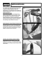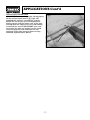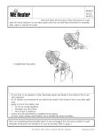
1
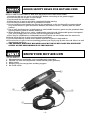
HOT AIR GUN
■ PART No.HG1601
■ STOCK No.53266
• INSTRUCTIONS •
IMPORTANT: PLEASE READ THESE INSTRUCTIONS CAREFULLY TO ENSURE
THE SAFE AND EFFECTIVE USE OF THIS TOOL.
ir
ot a te
T:
is h
o
TAN t of th ase n
R
O
e
n
l
IMP eleme ing. P f this
t
o
a
e
n
r
wi
e
e co atio
ting tectiv aporiz may b 20-30
hea
ro
v
t
ke
The as a p to the e smo he firs
h
e
m
rt
gun hat du ng, so g/afte e only.
t
ti
s
in
coa ed dur s of u
d
t
era secon
g en
07/97
SPECIFICATION
Whilst every effort has been made to ensure that the information given in this manual is correct at
the time of going to print, the Draper Tools policy of continuous improvement determines the right
to change specification without notice.
PART No.. . . . . . . . . . . . . . . . . . . . . . . . . . . . . . . . . . . . . . . . . . . . . . . . . . . . . . . . . . . . . . . . HG1601
STOCK No. . . . . . . . . . . . . . . . . . . . . . . . . . . . . . . . . . . . . . . . . . . . . . . . . . . . . . . . . . . . . . . . . 53266
Power . . . . . . . . . . . . . . . . . . . . . . . . . . . . . . . . . . . . . . . . . . . . . . . . . . . . . . . . . . . . . . . . . . . 1600W
Temperature . . . . . . . . . . . . . . . . . . . . . . . . . . . . . . . . . . . . . . . . . . . . . . . . . . . . . . . . . . 400/590°C
Voltage . . . . . . . . . . . . . . . . . . . . . . . . . . . . . . . . . . . . . . . . . . . . . . . . . . . . . . . . . . . . . . 230V/50Hz
Air flow volume . . . . . . . . . . . . . . . . . . . . . . . . . . . . . . . . . . . . . . . . . . . . . . . . . . . . 300/500 L/min
Weight (machine only) . . . . . . . . . . . . . . . . . . . . . . . . . . . . . . . . . . . . . . . . . . . . . . . . . . . . . . 784g.
The typical sound pressure level of this tool is less than 78dbA.
The noise level whilst working could exceed 85dbA - WEAR EAR PROTECTION.
Typically the hand-arm vibration is below 2.5m/s2.
GUARANTEE
Draper machine tools have been carefully tested and inspected before shipment and are
guaranteed to be free from defective materials and workmanship for a period of 12 months from
the date of purchase except where tools are hired out when the guarantee period is reduced to
ninety days from the date of purchase.
Should the machine develop any fault, please return the complete tool to your nearest authorized
warranty repair agent or contact Draper Tools Limited, Hursley Road, Chandler’s Ford, Eastleigh,
Hampshire, SO53 1YF. England. Telephone: (01703) 266355.
If upon inspection it is found that the fault occurring is due to defective materials or workmanship,
repairs will be carried out free of charge. This guarantee does not apply to normal wear and tear,
nor does it cover any damage caused by misuse, careless or unsafe handling, alterations,
accident, or repairs attempted or made by any personnel other than the authorized Draper
warranty repair agent.
This guarantee applies in lieu of any other guarantee expressed or implied and variations of its
terms are not authorized.
Your Draper guarantee is not effective unless you can produce upon request a dated receipt or
invoice to verify your proof of purchase within the 12 month period.
Please note that this guarantee is an additional benefit and does not affect your statutory rights.
DRAPER TOOLS LIMITED.
-1-
POWER SUPPLY
CONNECTING YOUR MACHINE TO THE POWER SUPPLY:
To eliminate the possibility of an electric shock, your machine has been fitted with a BS approved,
non rewireable moulded plug and cable which incorporates a fuse, the value of which is indicated
on the pin face of the plug. Should the fuse need to be replaced an
approved BS1362 fuse
must be used of the same rating, marked thus
.
The fuse cover is detachable, never use the plug with the cover omitted. If a replacement fuse
cover is required, ensure it is of the same colour as that visible on the pin face of the plug (i.e.
red). Fuse covers are available from your Draper Tools stockist.
If the fitted plug is not suitable, it should be cut off and destroyed. *The end of the cable should
now be suitably prepared and the correct type of plug fitted. See below.
*WARNING:
A plug with bare flexible wires exposed is hazardous if engaged in a live power socket outlet.
WARNING: THIS APPLIANCE MUST BE EARTHED.
Green and Yellow - Earth, Blue - Neutral, Brown - Live.
As these colours may not correspond with the coloured markings identifying the terminals in your
plug, proceed as follows:
The wire which is coloured green and yellow must be connected to the terminal in the plug which
is marked with the letter ‘E’ or by the earth symbol
or coloured green or green and yellow.
The wire which is coloured blue must be connected to the terminal which is marked with the letter
‘N’ or coloured black or blue.
The wire which is coloured brown must be connected to the terminal which is marked with the
letter ‘L’ or coloured red or brown.
N.B. Three phase machines must be connected by a qualified electrician.
EXTENSION LEAD CHART:
Extension lead sizes shown assure a voltage drop of not more than 5% at rated load of tool.
Ampere rating
(on Name plate)
Extension Cable Length
7.5m
15m
22.5m
30m
45m
3
6
10
13
2
Wire Size mm
0.75
1.0
0.75
1.0
0.75
1.0
0.75
1.25
1.25
1.5
0.75
0.75
0.75
0.75
0.75
1.25
1.5
1.5
1.5
2.5
IMPORTANT:
Please note this machine is fitted with safety thermal overload protection. If the product, for
example, is used too close to the workpiece - resulting in overheating, the thermal overload
protection will be activated and stop the motor/heating of the machine.
The hot air gun should be switched off and disconnected from the power supply, allowing the
machine to totally cool down - before restarting work.
Remember the nozzle will remain hot for sometime - a safe storage location should be used.
-2-
SAFETY WARNING
WARNING
Please read the following instructions carefully, failure to do so could lead to serious personal
injury.
IMPORTANT
Draper Tools Limited recommends that this machine should not be modified or used for any
application other than that for which it was designed. If you are unsure of its relative applications
do not hesitate to contact us in writing and we will advise you.
GENERAL SAFETY INSTRUCTIONS FOR MACHINE TOOLS
1. KNOW YOUR MACHINE TOOL
Read and understand the owner's manual and labels affixed
to the tool. Learn its application and limitations as well as
the specific potential hazards peculiar to this tool.
2. KEEP GUARDS IN PLACE
and in working order.
12. SECURE WORK
Use clamps or a vice to hold work. This frees both hands to
operate tool.
13. DO NOT OVERREACH
Keep proper footing and balance at all times.
3. REMOVE ADJUSTING KEYS AND WRENCHES
Form a habit of checking to see that keys and adjusting
wrenches are removed from tool before turning it on.
14. MAINTAIN TOOLS WITH CARE
Keep tools sharp and clean for best and safest
performance. Follow instructions for lubricating and
changing accessories.
4. KEEP WORK AREA CLEAN
Cluttered areas and benches invite accidents. Floor must
not be slippery due to oil or sawdust.
15. DISCONNECT POWER TO THE TOOLS
Before servicing, when changing accessories such as
cutters etc.
5. AVOID DANGEROUS ENVIRONMENT
Do not use power tools in damp or wet locations or expose
them to rain. Keep work area well lit. Provide adequate
surrounding work space.
16. AVOID ACCIDENTAL STARTING
Make sure switch is in 'OFF' position before plugging in
cable to the power supply.
17. USE RECOMMENDED ACCESSORIES
Consult the owner's manual for recommended accessories.
Follow the instructions that accompany the accessories. The
use of improper accessories may cause hazards.
6. KEEP CHILDREN AWAY
All visitors should be kept a safe distance from work area.
7. MAKE WORKSHOP CHILDPROOF
- with padlocks, master switches, or by removing starter
keys.
18. NEVER STAND ON TOOL
Serious injury could occur if the tool is tipped or if the
cutting tool is accidentally contacted. Do not store
materials above or near the tool such that it is necessary to
stand on the tool to reach them.
8. DO NOT FORCE TOOL
It will do the job better and safer at the rate for which is
was designed.
9. USE RIGHT TOOL
Do not force tool or attachment to do a job for which is was
not designed.
10. WEAR PROPER CLOTHING
Do not wear loose clothing, gloves, neckties or jewellery
(rings, wristwatches) to catch in moving parts. NON SLIP
footwear is recommended.Wear protective hair covering to
contain long hair. Roll long sleeves above the elbow.
11. USE SAFETY GOGGLES (Head Protection)
Wear safety goggles (must comply with BS 2092) at all
times. Normal spectacles only have impact resistant lenses,
they are NOT safety glasses. Also, use face or dust mask if
cutting operation is dusty and ear protectors (plugs or
muffs) during extended periods of operation.
19. CHECK DAMAGED PARTS
Before further use of the tool, a guard or other part that is
damaged should be carefully checked to ensure that it will
operate properly and perform its intended function. Check
for alignment of moving parts, breakage of parts, mounting
and any other conditions that may affect its operation. A
guard or other part that is damaged should be properly
repaired or replaced.
20. DIRECTION OF FEED
Feed work into a blade or cutter against the direction of
rotation of the blade or cutter only.
21. NEVER LEAVE MACHINE RUNNING UNATTENDED
Turn power off. Do not leave machine until it comes to a
complete stop.
-3-
ADDED SAFETY RULES FOR HOT AIR GUNS
NOTE: A FIRE COULD ARISE IF THIS HOT AIR GUN IS NOT USED WITH CARE.
1. Ensure that the hot air gun is switched OFF before connecting to the power supply.
2. Do not use this hot air gun as a hair dryer.
3. Do not touch the hot metal nozzle.
4. Allow the hot air gun to cool down completely before storing.
5. Do not direct the flow of hot air at persons or animals.
6. Do not hold the metal nozzle too close to the workpiece as the air flow will be restricted and
may cause the hot air gun to overheat. Position the nozzle at least 1" (25mm) from the work
surface.
7. Use in well ventilated area as poisonous or inflammable fumes or gases may be produced from
certain plastics, paints or similar materials.
8. When working with or near easily combustable materials and inflammable gases, take special
care. (Do not apply heat to any one area for long periods of time).
9. Heat may be conducted to combustible materials which are not visible from the work area.
10. Never leave the hot air gun running whilst unattended.
11. Do not look directly into the metal nozzle when the machine is switched on.
12. Place the hot air gun in its free standing position (see Fig.4 page 5) after use and allow it to cool
down before storing it.
13. THE CERAMIC RODS MAY BECOME LOOSE BUT IN NO WAY DOES THIS ALTER THE
SAFETY OR THE PERFORMANCE OF THE PRODUCT.
KNOW YOUR HOT AIR GUN
1.
2.
3.
4.
5.
BS approved non-rewireable 3 pin moulded plug and cable.
ON/OFF, air flow and temperature control switch (three position).
Metal nozzle.
Hanging ring for storage/free standing support.
Air intake vents.
✙✌
✖✌
✗✌
✘✌
✕✌
-4-
OPERATION
IMPORTANT - ensure that the machine is
switched OFF before connecting to the power
supply.
ON/OFF SWITCH
The ON/OFF switch has three positions/settings,
see Figs.1, 2 and 3. Fig.1 shows the switch in
the OFF position, 2 shows the switch in low heat
position and Fig.3 shows the switch in the
higher heat position.
Fig.1
Fig.2
Fig.3
FREESTANDING OPERATION
This hot air gun can be positioned as shown in
Fig.4 (free standing), this allows the user to
have both hands free which is essential for
certain applications, eg. pipe bending, plastic
welding etc. Position the hot air gun on it’s end
and position the support foot ✪✌ as shown in
Fig.4.
Fig.4
✪✌
-5-
APPLICATIONS
The following instructions should only be used
as a guide as the ideal temperature should be
ascertained by performing a test on the
workpiece. Heating efficiency will vary
depending on the properties of the workpiece,
and the distance kept between the metal nozzle
and the workpiece.
PAINT REMOVAL Fig.5
Switch the hot air gun on to the higher heat
setting and position the metal nozzle at least 1"
from the work surface. Now move the hot air
gun gently over a small area, as the paint
softens and blisters carefully remove the paint
using a suitable scraper or spatula. Note: Do not
heat the paint too long as the paint will burn
thus making it more difficult to remove.
Fig.5
PAINT REMOVAL FROM WINDOW FRAMES Fig.6
IMPORTANT: Do not direct the hot air gun at the
glass during use as it may crack. Always use
the glass protection nozzle ✪✌ (not supplied
see optional accessories, page 8). Do not touch
the glass with the hot metal protection nozzle.
Repeat as above for paint removal.
✪✌
Fig.6
HEATING AND SHAPING PLASTIC TUBING
Fit the reflector hook nozzle ✫✌ Fig.7 (not
supplied see optional accessories, page 8).
Switch the hot air gun on to the low heat setting,
carefully heat the tubing evenly moving it from
side to side.
Fig.7
-6-
✫✌
APPLICATIONS Cont’d
DEFROSTING WATER PIPES
IMPORTANT: Do not defrost plastic tubing/piping.
Fit the relector hook nozzle ✫✌ Fig.8 (not
supplied see optional accessories, page 8).
Switch the hot air gun on to the higher heat
setting, gently heat the frozen area of the pipe
starting from the edge of the area and moving
in towards the centre. IMPORTANT: take care
not to heat the pipe too quickly as this could
cause the pipe to crack and burst. Do not
overheat water pipe joints as these are only
soldered together (max. 200°C).
Fig.8
✫✌
-7-
MAINTENANCE
WARNING
For your own safety always turn the main switch on the machine OFF and remove the plug from
the power source before carrying out any maintenance or troubleshooting.
Check that the air inlet vents are clean and not blocked in any way.
IMPORTANT:
Please note all repairs/adjustments should be carried out by a qualified person.
POWER DIVISION HELPLINE:
01703 494313
OPTIONAL ACCESSORIES
The following accessories are available from your local Draper Stockist.
GLASS PROTECTION NOZZLE
Part No. AHG1
Stock No.34410
WALL SCRAPERS
Part No. 49325 (2")
Stock No.13865
Part No. 49335 (3")
Stock No. 13866.
REFLECTOR HOOK NOZZLE
Part No. AHG2
Stock No.34412
COMBINATION SHAVE HOOK
Part No. D116
Stock No. 52677
SCRAPER NOZZLE
Part No. AHG4
Stock No.34550
-8-
DECLARATION OF CONFORMITY
We Draper Tools Ltd. Hursley Road, Chandler’s Ford, Eastleigh, Hampshire.
SO53 1YF. England.
Declare under our sole responsibility that the product:
Part No. HG1601.
Stock No. 53266.
Description:- Hot Air Gun
To which this declaration relates is in conformity with the following
directive(s) 73/23/EEC & 89/336/EEC
with reference to EN60335-1, EN60335-2-30, EN50082-1, IEC801-2, IEC801-3,
IEC801-4, EN55014, EN60555-2 & EN60555-3.
J.N. DRAPER
Managing Director
-9-
NOTES
- 10 -
DRAPER TOOLS LIMITED,
Hursley Road, Chandler's Ford,
Eastleigh, Hants. SO53 1YF. England.
Tel: (01703) 266355.
Fax: (01703) 260784.
YOUR DRAPER STOCKIST
©Published by Draper Tools Ltd.
No part of this publication may be reproduced,
stored in a retrieval system or transmitted in
any form or by any means, electronic, mechanical
photocopying, recording or otherwise without prior
permission in writing from Draper Tools Ltd.