1
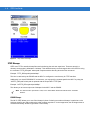
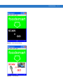
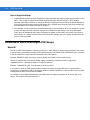
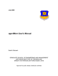
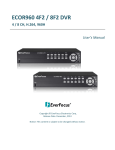
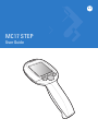
MC17 STEP
User Guide
MC17 STEP
User Guide
72E-103347-01
Rev. A
August 2007
ii
STEP User Guide
© 2007 by Motorola, Inc. All rights reserved.
No part of this publication may be reproduced or used in any form, or by any electrical or mechanical means,
without permission in writing from Motorola. This includes electronic or mechanical means, such as
photocopying, recording, or information storage and retrieval systems. The material in this manual is subject to
change without notice.
The software is provided strictly on an “as is” basis. All software, including firmware, furnished to the user is on
a licensed basis. Motorola grants to the user a non-transferable and non-exclusive license to use each
software or firmware program delivered hereunder (licensed program). Except as noted below, such license
may not be assigned, sublicensed, or otherwise transferred by the user without prior written consent of
Motorola. No right to copy a licensed program in whole or in part is granted, except as permitted under
copyright law. The user shall not modify, merge, or incorporate any form or portion of a licensed program with
other program material, create a derivative work from a licensed program, or use a licensed program in a
network without written permission from Motorola. The user agrees to maintain Motorola’s copyright notice on
the licensed programs delivered hereunder, and to include the same on any authorized copies it makes, in
whole or in part. The user agrees not to decompile, disassemble, decode, or reverse engineer any licensed
program delivered to the user or any portion thereof.
Motorola reserves the right to make changes to any software or product to improve reliability, function, or
design.
Motorola does not assume any product liability arising out of, or in connection with, the application or use of
any product, circuit, or application described herein.
No license is granted, either expressly or by implication, estoppel, or otherwise under any Motorola, Inc.,
intellectual property rights. An implied license only exists for equipment, circuits, and subsystems contained in
Motorola products.
MOTOROLA and the Stylized M Logo and Symbol and the Symbol logo are registered in the US Patent &
Trademark Office. Bluetooth is a registered trademark of Bluetooth SIG. Microsoft, Windows and ActiveSync
are either registered trademarks or trademarks of Microsoft Corporation. All other product or service names
are the property of their respective owners.
Motorola, Inc.
One Motorola Plaza
Holtsville, New York 11742-1300
http://www.symbol.com
Patents
This product is covered by one or more of the patents listed on the website: www.symbol.com/patents
iii
Revision History
Changes to the original manual are listed below:
Change
-01 Rev A
Date
08/10/2007
Description
Initial release.
iv
STEP User Guide
Table of Contents
Patents.................................................................................................................................................. ii
Revision History.................................................................................................................................... iii
About This Guide
Introduction ...........................................................................................................................................
Chapter Descriptions ............................................................................................................................
Notational Conventions.........................................................................................................................
Related Documents ..............................................................................................................................
i
i
i
ii
Chapter 1: Installation
Introduction ..........................................................................................................................................
Download .............................................................................................................................................
Setup ...................................................................................................................................................
Removal ...............................................................................................................................................
Re-Installing the Operating System ...............................................................................................
STEP Removal AirBEAM Package ................................................................................................
1-1
1-1
1-1
1-2
1-2
1-2
Chapter 2: Customization
Introduction ..........................................................................................................................................
Enhancements Not Requiring PSS Changes ......................................................................................
Text Colors .....................................................................................................................................
Screen Layout ................................................................................................................................
Panel Bitmaps ................................................................................................................................
Help Screen ...................................................................................................................................
STEP Bitmaps ................................................................................................................................
COLOR Bitmaps ......................................................................................................................
Notes on Using Color Bitmaps .................................................................................................
Enhancements Which Would Require PSS Changes .........................................................................
Model ID .........................................................................................................................................
2-1
2-1
2-1
2-3
2-4
2-5
2-6
2-6
2-8
2-8
2-8
vi
Index
STEP User Guide
About This Guide
Introduction
This guide provides information about using the Symbol Terminal Emulation Program (STEP) Client software on
the MC17 mobile computer.
NOTE
Screens and windows pictured in this guide are samples and can differ from actual screens.
Chapter Descriptions
Topics covered in this guide are as follows:
• Chapter 1, Installation provides information installing and removing the STEP software.
• Chapter 2, Customization provides information on customizing the STEP client.
Notational Conventions
The following conventions are used in this document:
• Italics are used to highlight the following:
• Chapters and sections in this and related documents
• Dialog box, window and screen names
• Drop-down list and list box names
• Check box and radio button names
• Icons on a screen.
• Bold text is used to highlight the following:
• Key names on a keypad
• Button names on a screen or window.
ii
STEP User Guide
• bullets (•) indicate:
• Action items
• Lists of alternatives
• Lists of required steps that are not necessarily sequential
• Sequential lists (e.g., those that describe step-by-step procedures) appear as numbered lists.
NOTE
This symbol indicates something of special interest or importance to the reader. Failure to read the note will not
result in physical harm to the reader, equipment or data.
CAUTION
This symbol indicates that if this information is ignored, the possibility of data or material damage may
occur.
WARNING!
This symbol indicates that if this information is ignored the possibility that serious personal
injury may occur.
Related Documents
• MC17 Quick Reference Guide, p/n 72-100298-xx
• MC17 Product Reference Guide, p/n 72-100467-xx
• Symbol Mobility Developer Kit for C (SMDK for C), available at: http://devzone.symbol.com/.
• MC17 Device Configuration Package (DCP), available at: http://devzone.symbol.com/.
• ActiveSync 4.2 software, available at: http://www.microsoft.com.
For the latest version of this guide and all guides, go to: http://www.symbol.com/manuals.
About This Guide
iii
Service Information
If you have a problem with your equipment, contact Motorola Enterprise Mobility Support for your region. Contact
information is available at: http://www.symbol.com/contactsupport.
When contacting Enterprise Mobility Support, please have the following information available:
• Serial number of the unit
• Model number or product name
• Software type and version number.
Motorola responds to calls by E-mail, telephone or fax within the time limits set forth in support agreements.
If your problem cannot be solved by Motorola Enterprise Mobility Support, you may need to return your equipment
for servicing and will be given specific directions. Motorola is not responsible for any damages incurred during
shipment if the approved shipping container is not used. Shipping the units improperly can possibly void the
warranty.
If you purchased your Enterprise Mobility business product from a Motorola business partner, contact that business
partner for support.
iv
STEP User Guide
Chapter 1 Installation
Introduction
This chapter provide information on installation the MC17 STEP software on the MC17 mobile computer.
Download
Download the MC17 STEP emulator software from the Support Central web site, http://www.symbol.com/support.
Setup
In keeping with A3a compatibility, extract the zip file containing the STEP Client for the MC17 into the A3a TFTP
directory (TFTPBOOT\symbol\pss\A3a).
If this is the first installation, generate RD Client bar codes to deploy the MC17 Step Client. If this is an upgrade
then the new client should automatically deploy on the next reboot of each mobile computer. You may force all of
the mobile computers to reboot through the PSS server console.
RD Client bar codes should be generated to deploy "A4Step.apd" from that directory. Refer to the MC17 User
Guide for detailed information on the RD Client.
On the MC17:
1.
Select RD Client from the App Launcher menu.
2.
Scan the configuration bar codes.
3.
Wait for configuration to complete.
4.
Exit RD Client.
5.
Select Reset from the App Launcher menu.
6.
When the mobile computer reboots, AirBEAM downloads the A4 Step Package and install it.
7.
The mobile computer reboots.
1-2
STEP User Guide
8.
The STEP application starts automatically, and connect to the TFTP server for additional configuration
information.
Removal
The STEP Client can be removed from the mobile computer by:
• re-installing the operating system
• using a STEP Removal AirBEAM package.
Re-Installing the Operating System
Re-installing the operating system completely removes the installed STEP Client software from the mobile
computer.
STEP Removal AirBEAM Package
An STEP Removal AirBEAM package available on the support central site to remove the STEP Client from the
mobile computer.
To remove the STEP Client:
1.
Download the STEP Removal AirBEAM package from Support Central.
2.
Unzip the STEP Removal AirBEAM package to the A3a TFTP directory (TFTPBOOT\symbol\pss\A3a).
3.
Reboot the mobile computer that you wish to remove the STEP Client from.
4.
During the initialization of the STEP Client the message “Waiting for Network” displays. Press the scan trigger
(yellow button) during the first 2 seconds of the STEP Client initialization.
5.
Within a few seconds the scanner comes on.
6.
Scan the A4ExitStep bar code.
Figure 1-1 A4ExitStep Bar Code
7.
The STEP Client installation exits and the App Launcher displays.
8.
Use Rapid Deployment Client to deploy the A4StepRemove.apd file. If asked, reboot the mobile computer.
There is a reboot option on the AppLauncher menu.
9.
App Launcher starts automatically after the reboot. You can now deploy any other application using the Rapid
Deployment Client.
Alternatively, if you wish to remove STEP from all of you mobile computers, you may simple delete the A4Step.apd
file and rename the A4StepRemove.apd file to A4Step.apd. Then reboot all your mobile computers either manually
or from the PSS server console.
After STEP has been removed you may be required to manually reboot all of the mobile computers.
Chapter 2 Customization
Introduction
The SETEP software has several customizations that can be made to enhance the end-user experience. These
can be categorized into the following:
• Enhancements not requiring PSS changes.
• Text colors
• Screen layout
• Panel bitmaps
• Help screen
• STEP bitmaps.
• Enhancements which would require PSS changes.
• MODEL ID
• WAV files.
The majority of these customizations are stored in the A3a.CFG file which is in the directory “symbol/pss/A3a” in
the TFTPRoot directory.
Enhancements Not Requiring PSS Changes
Text Colors
Figure 2-1 shows the default screen configuration. In the default configuration the text is set to black letters on a
white background.
2-2
STEP User Guide
Figure 2-1 Default Text Colors
The text foreground and background colors are set through the A3a.CFG file. The text foreground color is set by
the “TEXTCOLOR=r,g,b” command. Where the r,g,b values are replaced by numbers between 0 and 255 inclusive.
The text background color is set by the “TEXTBACKGROUND=r,g,b” command. For example, to set the text to
white on a blue background use the following commands:
TEXTCOLOR=255,255,255
TEXTBACKGROUND=0,0,255
Figure 2-2 shows the results in the text area.
Customization
2-3
Figure 2-2 Text Set to White on Blue Background
NOTE
The TEXTCOLOR and TEXTBACKGROUND commands do not take effect until the A3a.CFG file has
been downloaded and processed.
Screen Layout
The default screen layout is shown in Figure 2-1. The screen is divided into three sections:
• top logo area
• middle STEP text area
• bottom fill area.
Customization is done by dividing the screen horizontally into panels. Each panel may contain a separate bitmap or
be designated as the text area. The software supports two through five panels. The panels are numbered vertically
staring at the top with Panel 1. One panel must be designated as the “TEXT” panel, and optionally one of the
panels may be configured as the “HELP” panel. Each panel not designated as the TEXT panel should be assigned
a bitmap file to display in that panel. Bitmaps should be pre-scaled to fit in that panel.
The number of panels is configured through the “NUMPANELS=n” command where n is 2 through 5.
Example: “NUMPANELS=3”
The vertical size of each panel is configured though the “PANELxSTART=nnn” command where x is the panel
number and nnn is the pixel start position of the panel.
NOTE
PANEL1START is already configured.
Example:”PANEL2START=156”
2-4
STEP User Guide
The TEXT panel is configured by the “TEXTPANEL=n” command where the n is the number of the panel to be
used for the TEXT portion of the screen.
Example: “TEXTPANEL=2”
Complete example:
NUMPANELS=3
TEXTPANEL=2
PANEL2START=156
PANEL3START=300
NOTE
The vertical size of the TEXT panel must be 144 for everything to work properly.
Panel Bitmaps
Panel bitmaps are configured through the “PANELn=filename.bmp” command where filename.bmp is the name of
the bitmap for panel n.
NOTE
The panel bitmap files must be placed in the A3a download directory, TFTPBOOT\symbol\pss\A3a.
Example: “PANEL1=foodsmart.bmp”
Example: Using the following Configuration lines.
TEXTCOLOR=255,255,255
TEXTBACKGROUND=0,0,255
NUMPANELS=3
TEXTPANEL=2
PANEL1=foodsmart.bmp
PANEL3=SoftKeys.bmp
PANEL2START=156
PANEL3START=300
Will result in a screen like below, when using a bitmap for a fiction grocery store (foodsmart), and a softkey label
bar.
Customization
2-5
Figure 2-3 Panel Bitmap Example
NOTE
The bottom panel in this example is used to label the softkeys.
Help Screen
The STEP Client also has the capability of displaying an additional bitmap when the center softkey is depressed.
The panel for the Help screen is configured through the “HELPPANEL=n” command where n is replaced by the
panel number to be replaced with the help bitmap when the key is depressed. The Help bitmap is configured
through the “HELPBITMAP=filename.bmp” command where the filename.bmp is replaced with the help bitmap file
name.
NOTE
The help bitmap files must be placed in the A3a download directory, TFTPBOOT\symbol\pss\A3a.
Example:
HELPPANEL=1
HELPBITMAP=Help.bmp
These along with the previous set of configuration lines results in the following image when the center softkey is
depressed.
2-6
STEP User Guide
Figure 2-4 Help Panel Example
STEP Bitmaps
STEP uses TFTP to transfer bitmap files used in delivering the end-user experience. These are stored in a
directory structure that is defaulted to “ast3step”. This default directory can be changed via the A3a.CFG file using
the command “TFTP_DIR=path” where path is replace with the directory where the files are stored.
Example: “TFTP_DIR=symbol/pss/ast3step”
This line is used both by the PS3050 and the MC17 to configure the root directory for TFTP transfers.
Additionally, in a mixed PS3050/MC17 environment, you may specify a separate path for the MC17 by using the
“A4TFTP_DIR=path” where path is replaced with the unique MC17 TFTP path.
Example: “A4TFTP_DIR=symbol/pss/A4Step”
This allows you to have a unique set of bitmaps for the MC17 and the PS3050.
NOTE
The A3a.CFG file is processed in order, so the “A4TFTPDIR” directive should follow the “TFTPDIR”
directive.
COLOR Bitmaps
The MC17 STEP allows you to use Color bitmaps in place of existing monochrome bitmaps. In particular a color
Ast3Logo.bmp file can really enhance the initial customer experience. In the image below, the left image shows a
monochrome bitmap, while the right shows a color bitmap.
Customization
Figure 2-5 Monochrome Bitmap
Figure 2-6 Color Bitmap
2-7
2-8
STEP User Guide
Notes on Using Color Bitmaps
• Legacy bitmaps (those used by the PS3050 and earlier terminals) are scaled to fit the native resolution of the
MC17. Thus in order to support both PS3050 resolution bitmaps (128x64) and MC17 TEXT Window
resolution (240x144), a decision on scaling the bitmap is made based on the width of the bitmap. Bitmaps of
128 or less pixels horizontally will be scaled based on the PS3050 native resolution and Larger bitmaps will
be scaled based on the native resolution of the MC17.
• Color bitmaps are much larger than monochrome bitmaps. A native resolution 24 bit color bitmap is in excess
of 100 times larger than the equivalent monochrome PS3050 resolution bitmap. This has a dual impact.
Firstly, the color bitmaps will take longer to download on startup, and secondly, they require more space in
flash memory, So, caution should be taken when using color bitmaps, and use of legacy bitmaps should be
used as much as possible.
Enhancements Which Would Require PSS Changes
Model ID
The MC17 STEP client defaults to reporting a model ID of “3040”, which is a legacy device (PS3040). This is done
to provide legacy compatibility with legacy PSS implementations. The PS3050 uses a “MODELID=nnnn” command
to set the model ID to support enhanced featured in later PSS systems.
Example “MODELID=3050” was used to uniquely identify the PS3050 in those newer system.
The MC17 supports this command for PS3050 legacy compatibility. In addition the MC17 support the
“A4MODELID=xxxx” command to support it’s enhanced features.
Example: “A4MODELID=1770” could be used to identify the MC17.
In this case it is up to the PSS system people to modify their system to support this device. In general this is
required only in mixed system (MC17 and legacy hardware; PS3050, PS3040 etc.), and even then only if you want
to distinguish the MC17 from the other hardware.
For example: In some PSS implementations the PSS system will display keys labels on the bottom line of the
display. This could be removed for the MC17.
Index
B
S
bullets . . . . . . . . . . . . . . . . . . . . . . . . . . . . . . . . . . . . . . ii
screen layout . . . . . . . . . . . . . . . . . . . . . . . . . . . . 2-1, 2-3
service information . . . . . . . . . . . . . . . . . . . . . . . . . . . . iii
SMDK for C . . . . . . . . . . . . . . . . . . . . . . . . . . . . . . . . . . ii
STEP bitmaps . . . . . . . . . . . . . . . . . . . . . . . . . . . . . . 2-1
bitmaps . . . . . . . . . . . . . . . . . . . . . . . . . . . . . . . . 2-6
STEP Removal AirBEAM package . . . . . . . . . . . . . . 1-2
Support Central web site . . . . . . . . . . . . . . . . . . . . . . 1-1
Symbol Mobility Developer Kit for C . . . . . . . . . . . . . . . ii
C
conventions
notational . . . . . . . . . . . . . . . . . . . . . . . . . . . . . . . . i
D
DCP . . . . . . . . . . . . . . . . . . . . . . . . . . . . . . . . . . . . . . . . ii
Device Configuration Package . . . . . . . . . . . . . . . . . . . ii
download . . . . . . . . . . . . . . . . . . . . . . . . . . . . . . . . . . 1-1
H
help screen . . . . . . . . . . . . . . . . . . . . . . . . . . . . .2-1, 2-5
I
information, service . . . . . . . . . . . . . . . . . . . . . . . . . . . .iii
installation . . . . . . . . . . . . . . . . . . . . . . . . . . . . . . . . . 1-1
N
notational conventions . . . . . . . . . . . . . . . . . . . . . . . . . . i
P
panel bitmaps . . . . . . . . . . . . . . . . . . . . . . . . . . .2-1, 2-4
R
RD Client bar codes . . . . . . . . . . . . . . . . . . . . . . . . . 1-1
removal . . . . . . . . . . . . . . . . . . . . . . . . . . . . . . . . . . . 1-2
T
text colors . . . . . . . . . . . . . . . . . . . . . . . . . . . . . . . . . 2-1
Index - 2
Motorola, Inc.
One Motorola Plaza
Holtsville, New York 11742, USA
1-800-927-9626
http://www.symbol.com
MOTOROLA and the Stylized M Logo and Symbol and the Symbol logo are registered in the U.S. Patent and Trademark Office.
All other product or service names are the property of their registered owners.
© Motorola, Inc. 2007
72E-103347-01 Revision A - August 2007