1
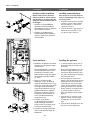
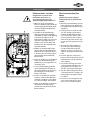
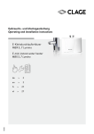
DE EN Elektronischer Durchlauferhitzer DBX Montageanleitung für den Fachhandwerker Electronically controlled instantaneous water heater DBX 02.15 Installing instructions for the professional DBX 18..27 BASITRONIC® Inhaltsverzeichnis Contents 1. Übersichtsdarstellung. . . . . . . . . . . . . . . . . . . . . . . . . . . . . . . . 3 1. Overview. . . . . . . . . . . . . . . . . . . . . . . . . . . . . . . . . . . . . . . . . 3 2. Sicherheitshinweise. . . . . . . . . . . . . . . . . . . . . . . . . . . . . . . . . 4 2. Safety instructions . . . . . . . . . . . . . . . . . . . . . . . . . . . . . . . . . . 4 3. Technische Daten. . . . . . . . . . . . . . . . . . . . . . . . . . . . . . . . . . . 5 3. Technical specifications . . . . . . . . . . . . . . . . . . . . . . . . . . . . . . 5 4. Abmessungen. . . . . . . . . . . . . . . . . . . . . . . . . . . . . . . . . . . . . . 6 4. Dimensions . . . . . . . . . . . . . . . . . . . . . . . . . . . . . . . . . . . . . . . 6 5. Installation. . . . . . . . . . . . . . . . . . . . . . . . . . . . . . . . . . . . . . . . 7 5. Installation. . . . . . . . . . . . . . . . . . . . . . . . . . . . . . . . . . . . . . . . 7 Montageort . . . . . . . . . . . . . . . . . . . . . . . . . . . . . . . . . . . . . . . 7 Installation site. . . . . . . . . . . . . . . . . . . . . . . . . . . . . . . . . . . . . 7 Montagezubehör. . . . . . . . . . . . . . . . . . . . . . . . . . . . . . . . . . . 8 Mounting accessories. . . . . . . . . . . . . . . . . . . . . . . . . . . . . . . . 8 Wandhalter montieren. . . . . . . . . . . . . . . . . . . . . . . . . . . . . . . 9 Installing the wall bracket . . . . . . . . . . . . . . . . . . . . . . . . . . . . 9 Anschlussstücke installieren. . . . . . . . . . . . . . . . . . . . . . . . . . 10 Installing connection pieces. . . . . . . . . . . . . . . . . . . . . . . . . . 10 Gerät montieren. . . . . . . . . . . . . . . . . . . . . . . . . . . . . . . . . . . 10 Installing the appliance . . . . . . . . . . . . . . . . . . . . . . . . . . . . . 10 6. Aufputzmontage . . . . . . . . . . . . . . . . . . . . . . . . . . . . . . . . . . 12 6. Direct connection. . . . . . . . . . . . . . . . . . . . . . . . . . . . . . . . . . 12 7. Elektroanschluss. . . . . . . . . . . . . . . . . . . . . . . . . . . . . . . . . . 13 Wiring diagram . . . . . . . . . . . . . . . . . . . . . . . . . . . . . . . . . . . 13 Schaltplan . . . . . . . . . . . . . . . . . . . . . . . . . . . . . . . . . . . . . . . 13 7. Electrical connection . . . . . . . . . . . . . . . . . . . . . . . . . . . . . . . 13 Bauliche Voraussetzungen. . . . . . . . . . . . . . . . . . . . . . . . . . . 13 Structural prerequisites . . . . . . . . . . . . . . . . . . . . . . . . . . . . . 13 Lastabwurfrelais. . . . . . . . . . . . . . . . . . . . . . . . . . . . . . . . . . . 13 Load shedding relay. . . . . . . . . . . . . . . . . . . . . . . . . . . . . . . . 13 Elektroanschluss von unten. . . . . . . . . . . . . . . . . . . . . . . . . . 14 Electrical connection from below. . . . . . . . . . . . . . . . . . . . . . 14 Elektroanschluss von oben. . . . . . . . . . . . . . . . . . . . . . . . . . . 15 Electrical connection from above. . . . . . . . . . . . . . . . . . . . . . 15 8. Erstinbetriebnahme. . . . . . . . . . . . . . . . . . . . . . . . . . . . . . . . 16 8. Initial operation. . . . . . . . . . . . . . . . . . . . . . . . . . . . . . . . . . . 16 Voreingestellte Auslauftemperatur ändern. . . . . . . . . . . . . . . 16 Modification of factory preset outlet temperature. . . . . . . . . 16 9. Wartungsarbeiten. . . . . . . . . . . . . . . . . . . . . . . . . . . . . . . . . . 17 9. Maintenance work. . . . . . . . . . . . . . . . . . . . . . . . . . . . . . . . . 17 Reinigung und Wechsel des Filtersiebes im Anschlussstück bei Cleaning and replacing the filter strainer. . . . . . . . . . . . . . . . 17 Unterputzanschluss . . . . . . . . . . . . . . . . . . . . . . . . . . . . . . . . 17 Cleaning and replacing the filter strainer if direct connected.18 Reinigung u. Wechsel des Filtersiebes bei Aufputzanschluss. 18 10. Environment and recycling. . . . . . . . . . . . . . . . . . . . . . . . . . 19 10. Umwelt und Recycling. . . . . . . . . . . . . . . . . . . . . . . . . . . . . 19 2 1. Übersichtsdarstellung 1. Overview Bei Ersatzteilbestellungen stets Gerätetyp und Serien nummer angeben! When ordering spare parts, please always specify the appliance model and serial number. Wandhalter Wall bracket Geräteunterteil Bottom part DBX Gerätehaube DBX hood Rückflussverhinderer Non-return valve Durchflussgeber Flow sensor Verbindungsrohr Connecting pipe Temperaturfühler Set Thermal sensor set Elektronik PCB Elektronikabdeckung PCB cover Heizelement mit Druckschalter (SDB) Heating element including safety pressure cut-out Klapphalter Control panel support Temperaturfühler Set Temperature sensor set Anschlussklemme Connecting terminal Einlaufrohr Inlet pipe Temperaturbegrenzer STB Safety thermal cut-out Feinfilter Fine filter Durchflussmengenregler Flow limiter Auslaufrohr Outlet pipe Rahmen Frame Warmwasseranschlussstück Hot water connection Kaltwasseranschlussstück Cold water connection Spritzwasserschutztülle Water splash protection sleeve G½” Einschraubnippel Screw-in nipples ½” Durchführungstülle Grommet 3 DBX 18..27 BASITRONIC® 2. Sicherheitshinweise 2. Safety instructions Lesen Sie diese Anleitung bis zur letzten Seite sorgfältig durch, bevor Sie das Gerät installieren oder benutzen! Bewahren Sie diese Anleitung für spätere Verwendung zusammen mit dem Gerät auf! Please read these instructions carefully before installing or using the appliance! Keep the instructions handy with the appliance for future use! Instruction manuals are intended for the specialist who is responsible for the installation of the appliance. Operation manuals are for the end user. Montageanleitungen richten sich an den Fachmann, der für die Installation des Gerätes verantwortlich ist. Gebrauchsanleitungen sind für den Endanwender bestimmt. The latest version of the instructions can be found online at www.clage.com. Die jeweils aktuelle Ausgabe dieser Anleitung ist online verfügbar unter: www.clage.de/downloads • Do not use the appliance until it has been correctly installed and unless it is in perfect working order. • Benutzen Sie das Gerät nur, nachdem es korrekt installiert wurde und wenn es sich in technisch ein wandfreiem Zustand befindet. • Do not remove the front cover under any circumstances before switching off the mains electrical supply to the unit. • Öffnen Sie niemals das Gerät, ohne vorher die Stromzufuhr zum Gerät dauerhaft unterbrochen zu haben. • Nehmen Sie am Gerät oder an den Elektro- und Wasserleitungen keine technischen Änderungen vor. • Never make technical modifications, either to the appliance itself or the electrical leads and water pipes. • Das Gerät muss geerdet werden. • The appliance must be earthed at all times. • Beachten Sie, dass Wassertemperaturen über ca. 43 °C, besonders von Kindern, als heiß empfunden werden und ein Verbrennungsgefühl hervorrufen können. Bedenken Sie, dass nach längerer Durch laufzeit auch die Armaturen entsprechend heiß werden. • Pay attention to the fact that water temperatures in excess of approx. 43 °C are perceived as hot, especially by children, and may cause a feeling of burning. Please note that the fittings and taps may be very hot when the appliance has been in use for some time. • Das Gerät ist nur für den Hausgebrauch und ähnliche Zwecke innerhalb geschlossener Räume geeignet und darf nur zum Erwärmen von Trinkwasser verwendet werden. • The appliance is only suitable for domestic use and similar applications inside closed rooms, and must only be used to heat incoming water from the mains supply. • Das Gerät darf niemals Frost ausgesetzt werden. • The appliance must never be exposed to frost. • Die auf dem Typenschild angegebenen Werte müssen eingehalten werden. • The values stated on the rating plate must be observed. • Im Störungsfall schalten Sie sofort die Sicherungen aus. Bei einer Undichtigkeit am Gerät schließen Sie sofort die Wasserzuleitung. Lassen Sie die Störung nur vom Werkskundendienst oder einem anerkannten Fachhandwerksbetrieb beheben. • In case of malfunction, disconnect the fuses immediately. In case of leaks, cut off the mains water supply instantly. Repairs must only be carried out by the customer service department or an authorised professional. • Dieses Gerät kann von Kindern ab 8 Jahren und darüber sowie von Personen mit verringerten physischen, sensorischen oder mentalen Fähigkeiten oder Mangel an Erfahrung und Wissen benutzt werden, wenn sie beaufsichtigt oder bezüglich des sicheren Gebrauchs des Gerätes unterwiesen wurden und die daraus resultierenden Gefahren verstehen. Kinder dürfen nicht mit dem Gerät spielen. Reinigung und Benutzerwartung dürfen nicht von Kindern ohne Beaufsichtigung durchgeführt werden. • This appliance can be used by children aged from 8 years and above and persons with reduced physical, sensory or mental capabilities or lack of experience and knowledge if they have been given supervision or instruction concerning use of the appliance in a safe way and understand the hazards involved. Children shall not play with the appliance. Cleaning and user maintenance shall not be made by children without supervision. 4 3. Technische Daten Typ 3. Technical specifications DBX 18 .. 27 BASITRONIC® DBX 21 DBX 24 DBX 18 Energieeffizienzklasse Nennleistung / -strom A *) 18 kW (26 A) Elektroanschluss Erforderl. Leiterquerschnitt 1) Warmwasser- max. at ∆t = 28 K leistung (l/min) 3) max. at ∆t = 38 K Nenninhalt Bauart Heizsystem Einsatzbereich bei 15 °C: spez. Wasserwiderstand spez. elektr. Leitfähigkeit Einlauftemperatur Einschalt- – max. Durchfluss 4) Druckverlust Temperatureinstellbereich Wasseranschluss Gewicht (mit Wasserfüllung) Schutzklasse nach VDE Geräuschprüfzeugnis DBX 27 21 kW (30 A) Energy efficiency class 24 kW (35 A) 3~ / PE 380..415 V AC 4.0 mm2 9,2 6,8 4.0 mm2 10,7 7,9 6.0 mm2 2) 12,3 9,0 27 kW (39 A) 3~ / PE 400 V AC 6.0 mm2 13,8 10,2 0,4 l geschlossen, 1,0 MPa (10 bar) Nennüberdruck / Pressure type 1,0 MPa (10 bar) Blankdraht IES® / Bare wire heating system IES® ≥ 1100 Ωcm ≤ 90 mS/m ≤ 30 °C 2,5 – 7,0 l/min 2,5 – 8,0 l/min 2,5 – 8,0 l/min 2,5 – 9,0 l/min 0,2 bar bei / at 2,5 l/min 1,3 bar bei / at 9,0 l/min 5) 30 °C – 60 °C G ½“ 3,65 kg I PA-IX 6762/I IP25 Schutzart / Sicherheit *) Die Angabe entspricht den Anforderungen für die ab September 2015 verbindliche EU-Verordnung Nr. 812/2013. 1) Maximal anschließbarer Kabelquerschnitt beträgt 10mm2 2) Bei Austausch eines 21 kW / 380 V-Gerätes kann der Leiterquerschnitt 4 mm2 übernommen werden. 3) Mischwasser 4) Durchfluss begrenzt, um optimale Temperaturerhöhung zu erreichen 5) Ohne Durchflussmengenregler Model Capacity set / current Electrical connection Min. required cable size 1) Hot water (l/min) 3) max. at ∆t = 28 K max. at ∆t = 38 K Rated volume Type Heating system Required specific water resistance @ 15 °C Specific electrical conductivity Inlet temperature Flow rate to switch on – max. flow rate 4) Pressure loss Temperature range Water connection Weight (when filled with water) VDE class of protection Noise level test certificate Type of protection / safety *) The declaration complies with the requirements of the EU regulation No 812/2013 being binding as of September 2015. 1) Maximum applicable cable size is 10mm2 2) When replacing a 21 kW / 380 V appliance the cable size of 4 mm2 can be adopted. 3) Mixed water 4) Flow rate limited to achieve optimum temperature rise 5) Without flow regulator 5 DBX 18..27 BASITRONIC® 4. Abmessungen 4. Dimensions 231 170 Maßangaben in mm 97 466 363 Dimensions in mm 56 231 100 6 5. Installation 5. Installation Zu beachten sind: The following regulations must be observed: •VDE 0100 •EN 806-2 •Bestimmungen der örtlichen Energie- und Wasserversorgungs unternehmen •Technische Daten und Angaben auf Typenschild •Die ausschließliche Verwendung von geeignetem und unbeschädigtem Werkzeug Für dieses Gerät ist aufgrund der Landesbau ordnungen ein allgemeines bauaufsichtliches Prüfzeugnis zum Nachweis der Verwendbarkeit hinsichtlich des Geräuschverhaltens erteilt. Based on the national constitution guidelines a general test certificate concerning the evidence of applicability of noise behaviour is granted. •Installation must comply with all statutory regulations, as well as those of the local electricity and water supply companies. •The rating plate and technical speci fications •Only intact and appropriate tools must be used Montageort Installation site • Gerät nur in einem frostfreien Raum installieren. Das Gerät darf niemals Frost ausgesetzt werden. • Appliance must only be installed in frost-free rooms. Never expose appliance to frost. • Das Gerät ist für eine Wandmontage vorgesehen und muss senkrecht mit untenliegenden Wasseranschlüssen installiert werden. • The Appliance must be wall mounted and has to be installed with water connectors downward. • Das Gerät entspricht der Schutzart IP25 und darf gemäß VDE 0100 Teil 701 im Schutzbereich 1 installiert werden. • The appliance complies with protection type IP25 and may therefore be installed in protection zone 1 according to VDE 0100 part 701. • Um Wärmeverluste zu vermeiden, sollte die Entfernung zwischen Durchlauferhitzer und Zapfstelle möglichst gering sein. • In order to avoid thermal losses, the distance between the instantaneous water heater and the tapping point should be as small as possible. • Für Wartungsarbeiten sollte in der Zuleitung ein Absperrventil installiert werden. Das Gerät muss für Wartungs zwecke zugänglich sein. • For maintenance work, a shut-off valve should be installed in the supplyline. The appliance must be accessible for maintenance work. • Kunstoffrohre dürfen nur verwendet werden, wenn diese DIN 16893 Reihe 2 entsprechen. Die Warmwasserleitungen müssen wärmegedämmt sein. • Plastic pipes may only be used if they conform to DIN 16893, Series 2. The hot water pipes must be thermally insulated. • Der spezifische Widerstand des Wassers muss bei 15 °C mindestens 1100 Ω cm betragen. Der spezifische Widerstand des Wassers kann bei Ihrem Wasser versorgungsunternehmen erfragt werden. • The specific resistance of the water must be at least 1100 Ωcm at 15°C. The specific resistance can be asked for with your water distribution company. 7 DBX 18..27 BASITRONIC® 5. Installation 5. Installation Montagezubehör Mounting accessories Für Installationen bei schwierigen Einbaubedingungen gibt es dieses Montagezubehör: For installations under difficult conditions, these mounting accessories are available: Mounting kit RDX RDX VDX Montagerahmen RDX (Art. no. 34100) (Art.-Nr. 34100) The instant water heater can be installed by means of this mounting kit in the below situations. The power supply cable is coming out of the wall at any place from behind the unit, but the wall has unusual surface conditions, making it difficult for installing the water heater. The power supply cable is coming from elsewhere and has to be connected to the back of the unit. Mit Hilfe dieses Montagerahmens kann der Durchlauferhitzer montiert werden, wenn der Elektroanschluss an beliebiger Stelle unter dem Gerät aus der Wand kommt oder die Leitung Aufputz verlegt ist. Rohrbausatz VDX Extension kit VDX (Art.-Nr. 34120) – RDX notwendig! – (Art. no. 34120) – RDX is necessary! – Mit Hilfe dieses Montagesatzes kann der Durchlauferhitzer montiert werden, wenn die Wasseranschlüsse versetzt oder vertauscht unter dem Gerät aus der Wand kommen oder seitlich auf der Wand zum Gerät führen. Der Elektroanschluss kann an beliebiger Stelle unter dem Gerät aus der Wand kommen, bzw. Aufputz verlegt sein. The instant water heater can be installed by means of this extension kit if the water pipes are coming displaced or exchanged out of the wall or if they are coming edgewise on the wall to the unit. The power supply could come out of the wall at any place under the unit or the wiring could be installed surface-mounted. Rohrbausatz UDX Extension kit UDX (Art.-Nr. 34110) – RDX notwendig! – (Art. no. 34110) – RDX is necessary! – Mit Hilfe dieses Montagesatzes kann der Durchlauferhitzer montiert werden, wenn die Wasseranschlüsse oberhalb des Gerätes enden. Der Elektroanschluss kann an beliebiger Stelle unter dem Gerät aus der Wand kommen, bzw. Aufputz verlegt sein. The instant water heater can be installed by means of this extension kit if the water-connections are expiring above the unit. The power supply could come out of the wall at any place under the unit or the wiring could be installed surfacemounted. UDX 8 5. Installation 5. Installation Wandhalter montieren Installing the wall bracket Hinweis: Wenn Sie diesen Durchlauf erhitzer im Austausch gegen ein anderes Fabrikat montieren, müssen in der Regel keine neuen Löcher für den Wandhalter gebohrt werden, der Punkt 2 entfällt dann. Note: If you install this instantaneous water heater in exchange for a conventional instantaneous water heater, there is generally no need to drill holes for the wall bracket, in this case step 2 would not be necessary. Spülen Sie die Wasserzuleitungen vor der Installation gründlich durch, um Schmutz aus den Leitungen zu entfer nen. Thoroughly rinse the water supply pipes before installation to remove soiling from the pipes. 1. Schrauben Sie die Einschraubnippel mit einem 12 mm-Innensechskantschlüssel in die beiden Wandanschlüsse. Dabei müssen die Dichtungen vollständig in das Gewinde eingeschraubt werden. Der Überstand der Einschraubnippel muss nach dem Festziehen mindestens 12 mm betragen. 2. Halten Sie die mitgelieferte Montage schablone an die Wand und richten Sie sie so aus, dass die Löcher in der Schablone über die Anschlüsse passen. Zeichnen Sie die Bohrlöcher entsprechend der Schablone an und bohren Sie die Löcher mit einem 6 mmBohrer. Setzen Sie die mitgelieferten Dübel ein. 3. Schrauben Sie den Wandhalter an. Fliesenversatz oder Unebenheiten lassen sich bis zu 30 mm durch die mitgelieferten Distanzhülsen ausgleichen. Die Distanzhülsen werden zwischen Wand und Wandhalter montiert. 9 1. Using a 12 mm hexagon socket screw key, screw the screw-in nipples into the wall connections. The seals must be fully screwed into the thread. After tightening, the double nipples must protrude by at least 12 mm. 2. Hold the included mounting template on the wall and align it so that the holes in the template fit over the connections. Mark the drill holes according to the template and drill them using a 6 mm drill. Insert the included dowels. 3. Screw in the wall bracket.Offset tiling or uneven surfaces can be compensated by up to 30 mm with the aid of the spacers supplied. The spacers are fitted between the wall and the wall bracket. DBX 18..27 BASITRONIC® 5. Installation 5. Installation Anschlussstücke installieren Installing connection pieces Hinweis: Ziehen Sie die Überwurf muttern maßvoll an, um die notwen dige Dichtheit zu erreichen, ohne die Armaturen oder die Rohrleitungen zu beschädigen. Note: Fasten the screw nuts with cau tion, to avoid damage to the valves or the piping system. • Schrauben Sie gemäß Abbildung das Kaltwasseranschlussstück mit Überwurfmutter und der ½“-Dichtung an den Kaltwasseranschluss. • Schrauben Sie das Warmwasser anschlussstück mit Überwurfmutter und der ½“-Dichtung an den Warm wasseranschluss. 1. As shown in the illustration, screw the cold water connection piece with the union nut and the ½“ seal onto the cold water connection. 2. Screw the hot water connection piece with the union nut and the ½“ seal onto the hot water connection. Gerät montieren Installing the appliance 1. Zum Öffnen des Gehäuses die Blende abnehmen und die zentrale Hauben schraube lösen. 1. To open the appliance hood, take off the faceplate and unscrew the main hood screw. • Im Austauschfall kann es vorkommen, dass die Elektrozuleitung im oberen Gerätebereich vorhanden ist. Der Elektroanschluss erfolgt dann gemäss der Beschreibung »Elektroanschluss von oben«. • When replacing an appliance, the electrical power supply cable may be connected in the upper part. Only in such case, follow the instructions “Electrical connection from above”. 2. Setzen Sie das Gerät auf den Wandhalter, so dass die Gewinde stange des Wandhalters in das vorgesehene Loch des Gerätes passt. Durch vorsichtiges Biegen der Gewinde stange des Wandhalters lassen sich gegebenenfalls kleine Korrekturen vornehmen. Die Wasseranschluss leitungen des Gerätes müssen sich jedoch ohne Gewaltanwendung anschrauben lassen. 3. Schrauben Sie die beiden ⅜“-Überwurfmuttern der Wasser anschlussleitungen des Gerätes jeweils mit der ⅜“-Dichtung auf die installierten Anschlussstücke. 4. Schrauben Sie die Kunststoffrändel mutter auf die Gewindestange des Wandhalters. 10 2. Place the appliance on the heater bracket so that the threaded rod of the wall bracket fits in the provided hole of the appliance. If necessary, slight corrections are possible by carefully bending the threaded rod of the wall bracket. However, it must be possible to screw on the water connection pipes of the appliance without applying force. 3. Screw the two ⅜“ union nuts of the appliance‘s water connection pipes, each with the ⅜“ seal, onto the fittings. 4. Screw the plastic knurled nut onto the threaded rod of the wall bracket. geschlossen closed (a) geöffnet open 5. Installation 5. Installation 5. Öffnen Sie die Wasserzuleitung und drehen Sie das Absperrventil (a) im Kaltwasseranschlussstück langsam auf (Position »geöffnet«). Prüfen Sie alle Verbindungen auf Dichtigkeit. 5. Open the water supply line to the unit and slowly open (position “open“) the shut-off valve (a) in the cold water connection piece. Check all connections for leaks. 6. Öffnen und schließen Sie danach mehrfach die zugehörige Warm wasserarmatur bis keine Luft mehr aus der Leitung austritt und der Durchlauf erhitzer luftfrei ist. 6. Next, open and close the hot water tapping valve several times until no more air emerges from the line and all air has been eliminated from the instantaneous water heater. 11 DBX 18..27 BASITRONIC® 6. Aufputzmontage 6. Direct connection Hinweis: Ziehen Sie die Überwurf muttern maßvoll an, um die notwen dige Dichtheit zu erreichen, ohne die Armaturen oder die Rohrleitungen zu beschädigen. Note: Fasten the screw nuts with cau tion, to avoid damage to the valves or the piping system. Bei Aufputzmontage sind die beiden ½“-Einschraubnippel und die ½“-Dich tungen mit den ½“-Überwurfmuttern des Warmwasser- und Kaltwasser anschlussstückes zu verschrauben. Die beiden ½“-Blindkappen der seitlichen Abgänge des Warm- und Kaltwasseranschlussstückes sind zu demontieren und mit dem offenen Ende der Einschraubnippel zu verschrauben. Die Warm- und Kaltwasseranschlussstücke sind dann mit den 3/8“-Dichtungen an die 3/8“-Überwurfmutter des Gerätes und Auslaufrohres zu verschrauben. Bei Aufputzmontage ist es sinnvoll, das Gerät mittels der mitgelieferten Distanzhülsen gemäß nebenstehender Zeichnung auf Abstand zu montieren. Dabei ist zu beachten, dass auch die beiden Befestigungsbohrungen im unteren Rohranschlussbereich benutzt werden. Die Bördelseite der Rohre sind mit ½“-Überwurfmuttern und ½“-Dichtungen an die seitlichen ½“-Abgänge des Warm- und Kaltwasseranschlussstückes zu schrauben. Abschließend sind die Ausbrüche für die Rohre in der Haube mit einem stumpfen Gegenstand heraus zubrechen. Bei Aufputzmontage beachten: Sieb in das Kaltwasseranschlussstück ein setzen! 12 For direct connection, the two ½“ screwin nipples and the ½“ seals must be screwed into the ½“ union nuts of the hot-water and cold-water connectors. The two ½“ caps of the side outlets of the hot-water and cold-water connectors must be removed and screwed onto the open end of the screw-in nipples. The hotwater and cold-water connectors must then be screwed into the 3/8“ union nut of the appliance and delivery pipe, together with the 3/8“ seals. For direct connection, it is advisable to mount the appliance at a distance as illustrated alongside, using the spacer sleeves supplied. It should therefore be noted that the two fixing holes near the lower pipe connections are also used. The flared end of the pipes must be screwed into the ½“ side outlets of the hot-water and cold-water connectors with ½“ union nuts and ½“ seals. The holes required for the pipes must then be broken out of the housing with the aid of a blunt implement. In case of direct connection please note: Put the strainer into the cold water connection! Schaltplan Wiring diagram 7. Elektroanschluss 7. Electrical connection Nur durch den Fachmann! Only by a specialist! Zu beachten sind: Please observe: •VDE 0100 •The installation must comply with current IEC and national local regu lations or any particular regulations, specified by the local electricity supply company •EN806-2 •Bestimmungen der örtlichen Energie- und Wasserversorgungsunternehmen 5 2 1 3 4 1. Elektronik 2. Heizelement 3. Sicherheitsdruckbegrenzer SDB 4. Klemmleiste 5. Sicherheitstemperaturbegrenzer STB 1. Electronic circuitry 2. Heating element 3. Safety pressure cut-out 4. Terminal strip 5. Safety thermal cut-out •Technische Daten und Angaben auf Typenschild •Gerät an den Schutzleiter anschließen! •The rating plate and technical speci fications •The unit must be earthed! Bauliche Voraussetzungen Structural prerequisites • Das Gerät muss dauerhaft an fest verlegte Leitungen angeschlossen werden. Das Gerät muss an den Schutzleiter angeschlossen werden. • The appliance must be installed via a permanent connection. Heater must be earthed! • Die Elektroleitungen müssen sich in einem einwandfreien Zustand befinden und dürfen nach der Montage nicht mehr berührbar sein. • Installationsseitig ist eine allpolige Trennvorrichtung mit einer Kontaktöffnungsweite von mindestens 3 mm pro Pol vorzusehen (z.B. über Sicherungen). • Zur Absicherung des Gerätes ist ein Sicherungselement für Leitungsschutz mit einem dem Gerätenennstrom angepassten Auslösestrom zu montieren. • The electric wiring should not be injured. After mounting, the wiring must not be direct accessible. • An all-pole disconnecting device (e.g. via fuses) with a contact opening width of at least 3 mm per pole should be provided at the installation end. • To protect the appliance, a fuse element must be fitted with a tripping current commensurate with the nominal current of the appliance. Lastabwurfrelais Load shedding relay Beim Anschluss weiterer Drehstromgeräte kann ein Lastabwurfrelais für elektronische Durchlauferhitzer (CLAGE Art.Nr. 82250) an den Außenleiter L2 angeschlossen werden. If further three-phase appliances are connected, a load shedding relay designed for electronic instantaneous water heaters (CLAGE no. 82250) can be connected to phase conductor L2. Um im niedrigen Leistungsbereich des Durchlauferhitzers (niedrige Temperatur und geringer Durchfluss) ein mögliches Flackern des Lastabwurfrelais zu vermeiden kann die Betriebsart »Lastabwurfrelais« aktiviert werden: To avoid possible jitter of the load shedding relay caused by low power consumption (low temperature set point and low water flow rate) the “Load-sheddingmode” can be activated as followed: • Gerät vom Netz trennen (z.B. durch Ausschalten der Sicherungen) • Disconnect the appliance from the power supply (e.g. by switching of the fuses) • Brücke auf die Leistungselektronik aufstecken (siehe Bild) • Insert the jumper on the power electronics (see picture) • Gerät wieder in Betrieb nehmen • Put the appliance into operation again 13 DBX 18..27 BASITRONIC® 7. Elektroanschluss 7. Electrical connection Elektroanschluss von unten Electrical connection from below Hinweis: Bei Bedarf kann die Anschlussklemme in den oberen Gerätebereich verlegt werden. Bitte folgen Sie hierzu den Anweisungen im nächsten Abschnitt. Vergewissern Sie sich vor dem Anschließen des Gerätes an das elekt rische Netz, dass die Stromversorgung ausgeschaltet ist! 1. Manteln Sie das Anschlusskabel ungefähr 6 cm über dem Wandaustritt ab. Schieben Sie die Spritzwasser schutztülle mit der kleineren Öffnung voran über das Anschlusskabel, so dass die Schutztülle wandbündig abschließt. Diese verhindert, dass eventuell eindringendes Wasser mit den Elektroleitungen in Kontakt kommt. Sie darf nicht beschädigt sein! Die Schutztülle muss verwendet werden! 2. Klapphalter nach rechts klappen. 3. Isolieren Sie die Kabel ab und schließen diese an die Anschlussklemmen gemäß des Schaltplans an. Das Gerät ist an den Schutzleiter anzuschließen. 4. Ziehen Sie die Schutztülle so weit über die Anschlusskabel, dass die Schutz tülle einwandfrei in die Aussparung der Zwischenwand passt. Achten Sie dabei auf die Ausrichtung der Schutz tülle entsprechend der Abbildung. Klappen Sie den Klapphalter zurück und rasten Sie ihn auf der Heizpatrone ein. 5. Setzen Sie das Gehäuse auf das Gerät und drehen Sie die Befestigungs schraube ein. Danach können Sie die Blende aufrasten. 14 Note: If necessary, the connecting ter minal can be displaced to the upper part of the appliance. If you want to do so, please follow the instructions in the next chapter. Check that the power supply is switched off prior to electrical con nection! 1. Dismantle approximately 6 cm off the connecting cable above the wall outlet. With the smaller opening ahead, slide the water splash protection sleeve over the connecting cable so that the sleeve is flush with the wall. This prevents any leaking water from coming into contact with the electrical leads. It must not become damaged! The protection sleeve must be used! 2. Open the control panel rightwards. 3. Strip the cables and plug them in the connecting terminals according to the wiring diagram. The appliance must be earthed. 4. Pull the protective sleeve over the connecting cables until the sleeve fits perfectly in the recess of the intermediate panel. Adjust the water splash protection sleeve as illustrated. Reinsert the control panel and lock it on the heating element. 5. Place the hood on the appliance and screw in the fastening screw. After that you can reinsert the faceplate. 7. Elektroanschluss 7. Electrical connection Elektroanschluss von oben Electrical connection from above Vergewissern Sie sich vor dem Anschließen des Gerätes an das elektrische Netz, dass die Stromversorgung ausgeschaltet ist! 1. Öffnen Sie die im oberen Geräte bereich vorhandene Sollbruchstelle (S) an der Prägung durch kräftigen Druck mit einem stumpfen Werkzeug (z.B. Schraubendreher). 2. Schneiden Sie die Durchführungs tülle entsprechend dem Zuleitungs querschnitt auf. Dabei soll die Öffnung in der Tülle etwas kleiner als der Querschnitt des Kabels sein, um einen optimalen Schutz gegen Wasser zu erzielen. Passen Sie die Tülle in den Durchbruch ein. Die Schutztülle muss verwendet werden! 3. Manteln Sie das Elektrokabel ungefähr 6 cm über dem Wandaustritt ab. Nehmen Sie das vorbereitete Gerät so in die Hand, dass Sie mit der anderen Hand das Kabel in die Gummitülle führen können. 4. Setzen Sie das Gerät so auf den Wand halter, dass die Gewindestange des Wandhalters in das vorgesehene Loch des Gerätes passt. 5. Lösen Sie die Befestigungsschraube der Anschlussklemme. Versetzen Sie die Anschlussklemme auf den oberen Fuß. Befestigen Sie die Anschluss klemme dort wieder. 6. Isolieren Sie die Kabel ab und schließen diese an die Anschlussklemmen gemäß des Schaltplans an. Das Gerät ist an den Schutzleiter anzuschließen. 7. Setzen Sie das Gehäuse auf das Gerät und drehen Sie die Befestigungs schraube ein. Danach können Sie die Blende aufrasten. 15 Check that the power supply is switched off prior to electrical con nection! 1. Open the prepared breaking point (S) in the upper part of the appliance by pressing with a blunt implement (e.g. srewdriver). 2. Slit the grommet to match the cable size. The opening in the grommet should be slightly smaller than the cross-section of the cable in order to ensure optimum protection against water. Fit the grommet into the opening. The protection grommet must be used! 3. Dismantle the cable roughly 6 cm above the point where it emerges from the wall. Hold the prepared appliance so that you can route the cable into the grommet with the other hand. 4. Place the appliance on the heater bracket so that the threaded rod of the wall bracket fits in the provided hole of the appliance. 5. Unscrew the fastening screw of the connecting terminal. Displace the connecting terminal to the upper foot. Affix the connecting terminal again. 6. Strip the cables and plug them in the connecting terminals according to the wiring diagram. The appliance must be earthed. 7. Place the hood on the appliance and screw in the fastening screw. After that you can reinsert the faceplate. DBX 18..27 BASITRONIC® 8. Erstinbetriebnahme 8. Initial operation Vor dem elektrischen Anschluss das Leitungsnetz und das Gerät durch mehrfaches, langsames Öffnen und Schließen der Warmwasserarmatur mit Wasser füllen und so vollstän dig entlüften. Nach jeder Ent leerung (z. B. nach Arbeiten in der Wasserinstallation, wegen Frostgefahr oder nach Reparaturen am Gerät) muss das Gerät vor der Wieder inbetriebnahme erneut entlüftet werden. Before making the electrical connec tion, fill the mains and the appliance with water by carefully opening and closing the hot water tap in order to vent completely. After every draining (e.g. after work on the plumbing sys tem or following repairs to the appli ance), the heater must be re-vented in this way before starting it up again. 1. Schalten Sie die Stromzufuhr zum Gerät ein. 2. Öffnen Sie das Warmwasserzapfventil. Überprüfen Sie die Funktion des Durchlauferhitzers. 3. Machen Sie den Benutzer mit dem Gebrauch vertraut und übergeben Sie ihm die Gebrauchsanleitung. 1. Switch on the power supply to the appliance. 2. Open the hot water tap. Check the function of the appliance. 3. Explain the user how the instantaneous water heater works and hand over the operating instructions. 4. Fill out the guarantee registration card and send it to the Central Customer Service or use the online registration. 4. Füllen Sie die Registrierkarte aus und senden diese an den Zentralkunden dienst oder registrieren Sie Ihr Gerät online. Voreingestellte Auslauf temperatur ändern Modification of factory preset outlet temperature Die Warmwasserauslauftemperatur ist werkseitig auf 50 °C voreingestellt. The factory set hot water outlet temperature is 50 °C. Durch drehen mit einem kleinen Schlitzschraubendreher (Klingenbreite ca. 2 mm) am Verstellpotentiometer kann diese Voreinstellung zwischen zwei Anschlägen im Bereich von ca. 30 °C bis 60 °C verändert werden. This factory setting can be modified within the range of approx. 30 °C to 60 °C by turning the readout potentiometer with a slotted screwdriver (width approx. 2 mm). Die eingestellte Warmwasserauslauf temperatur wird durch Drehung im Uhrzeigersinn verringert und durch Drehung gegen den Uhrzeigersinn erhöht. 16 The hot water outlet temperature will be decreased by clockwise rotation and increased by counterclockwise rotation. 9. Wartungsarbeiten 9. Maintenance work Wartungsarbeiten dürfen nur von einem anerkannten Fachhand werksbetrieb durchgeführt werden. Maintenance work must only be con ducted by an authorised professional. Reinigung und Wechsel des Filtersiebes im Anschlussstück bei Unterputzanschluss Cleaning and replacing the filter strainer Der Kaltwasseranschluss dieses Durchlauferhitzers ist mit einem integrierten Absperrventil und Sieb ausgestattet. Durch Verschmutzung des Siebes kann die Warmwasserleistung vermindert werden, so dass die Reinigung beziehungsweise der Austausch des Siebes wie folgt vorzunehmen ist: 1. Schalten Sie den Durchlauferhitzer an den Haussicherungen spannungsfrei und sichern Sie diese gegen unbeabsichtigtes Wiedereinschalten. geschlossen closed (a) geöffnet open 2. Öffnen Sie die Gerätehaube indem Sie die Blende abnehmen, die sich darunter befindliche Schraube lösen und die Haube abziehen. 3. Drehen Sie das Absperrventil im Kaltwasseranschlussstück (a) zu (Position »geschlossen«) 4. Drehen Sie die Verschlussschraube (b) aus dem Kaltwasseranschlussstück und nehmen Sie das Sieb (c) heraus. 5. Das Sieb kann nun gereinigt beziehungsweise ersetzt werden. 6. Nach Einbau des sauberen Siebes drehen Sie die Verschlussschraube fest. (b) (c) 7. Drehen Sie das Absperrventil im Kaltwasseranschlussstück langsam wieder auf (Position »geöffnet«). 8. Entlüften Sie das Gerät, indem Sie die zugehörige Warmwasserarmatur mehrfach langsam öffnen und schließen, bis keine Luft mehr aus der Leitung austritt. Sieb Strainer 9. Setzen Sie die Gerätehaube auf. Danach schalten Sie die Spannung an den Haussicherungen wieder ein. 17 The cold water connection of this instantaneous water heater is equipped with an integrated shut-off valve and a strainer. Soiling of the strainer may reduce the warm water output. Clean or replace the strainer as follows: 1. De-energize the instantaneous water heater (e.g. via deactivating the fuses) and prevent inadvertent reactivation of them. 2. To open the hood, take off the small face plate, loose the screw behind this cover and detach the hood. 3. Close the shut-off valve (a) in the cold water connection piece (position “closed“). 4. Unscrew the screw plug (b) from the cold water connection piece and take out the strainer (c). 5. The strainer can now be cleaned or replaced. 6. After fittingof the clean strainer tighten the screw plug. 7. Slowly reopen the shut-off valve in the cold water connection piece (position “open“). 8. Vent the unit by carefully opening and closing the affiliated warm water tap valve several times until air no longer emerges from the pipe. 9. Fit the hood of the unit. Then switch on the voltage again (e.g. via activating the fuses). DBX 18..27 BASITRONIC® 9. Wartungsarbeiten 9. Maintenance work Reinigung und Wechsel des Filtersiebes bei Aufputzanschluss Cleaning and replacing the filter strainer if direct connected Der Kaltwasseranschluss dieses Durchlauf erhitzers ist mit einem Sieb ausgestattet. Durch Verschmutzung des Siebes kann die Warmwasserleistung vermindert werden, so dass die Reinigung beziehungsweise der Austausch des Siebes wie folgt vorzunehmen ist: The cold water connection of this instantaneous water heater is equipped with a strainer. Soiling of the strainer may reduce the warm water output. Clean or replace the strainer as follows: 1. Schalten Sie den Durchlauferhitzer an den Haussicherungen spannungsfrei und sichern Sie diese gegen unbeabsichtigtes Wiedereinschalten. 2. Schließen Sie das Absperrventil in der Zulaufleitung. 3. Öffnen Sie die Gerätehaube indem Sie die Blende abnehmen, die sich darunter befindliche Schraube lösen und die Haube abziehen. 1. De-energize the instantaneous water heater (e.g. via deactivating the fuses) and prevent inadvertent reactivation of them. 2. Close the shut-off valve in the mains water supply of the instantaneous water heater. 3. To open the hood, take off the small face plate, loose the screw behind this cover and detach the hood. 4. Unscrew mains water inlet from connection piece and take out the strainer. 4. Lösen Sie das Zulaufrohr vom Wasseranschlussstück. 5. The strainer can now be cleaned or replaced. 5. Das Sieb kann nun gereinigt beziehungsweise ersetzt werden. 6. After refitting the clean strainer reconnect the mains water inlet to the connection piece. 6. Nach Einbau des sauberen Siebes verschrauben Sie das Zulaufrohr wieder am Wasseranschlussstück 7. Öffnen Sie langsam das Absperrventil in der Zulaufleitung. 8. Entlüften Sie das Gerät, indem Sie die zugehörige Warmwasserarmatur mehrfach langsam öffnen und schließen, bis keine Luft mehr aus der Leitung austritt. 9. Setzen Sie die Gerätehaube auf. Danach schalten Sie die Spannung an den Haussicherungen wieder ein. 18 7. Slowly reopen the shut-off valve in the mains water supply. 8. Vent the unit by carefully opening and closing the affiliated warm water tap valve several times until air no longer emerges from the pipe. 9. Fit the hood of the unit. Then switch on the voltage again (e.g. via activating the fuses). 10. Umwelt und Recycling 10. Environment and recycling Ihr Produkt wurde aus hochwertigen, wiederverwendbaren Materialien und Komponenten hergestellt. Beachten Sie bei einer Entsorgung, dass elektrische Geräte am Ende ihrer Lebensdauer vom Hausmüll getrennt entsorgt werden müssen. Bringen Sie dieses Gerät daher zu einer der kommunalen Sammelstellen, die Elektronikschrott kostenlos entgegennehmen. Diese ordnungsgemäße Entsorgung dient dem Umweltschutz und verhindert mögliche schädliche Auswirkungen auf Mensch und Umwelt, die sich aus einer unsachgemäßen Handhabung der Geräte am Ende ihrer Lebensdauer ergeben könnten. Genauere Informationen zur nächstgelegenen Sammelstelle bzw. Recyclinghof erhalten Sie bei Ihrer Gemeindeverwaltung. Geschäftskunden: Wenn Sie elektronische Geräte entsorgen möchten, treten Sie bitte mit Ihrem Händler oder Lieferanten in Kontakt. Diese halten weitere Informationen für Sie bereit. Your product was manufactured from high-quality, reusable materials and components. Please respect in case of discarding that electrical devices should be disposed of separately from household waste at the end of their service life. Therefore, please take this device to a municipal collection point that accepts electronic scrap on a free of charge basis. Disposing it correctly will support environmental protection and will prevent any potential negative effects on human beings and the environment that could arise from inappropriate handling of these devices at the end of their service life. Please contact your local authority for further details of your nearest designated collection point or recycling site. Business customers: If you wish to discard electronic equipment, please contact your dealer or supplier for further information. 19 CLAGE GmbH Pirolweg 1–5 21337 Lüneburg Deutschland Technische Änderungen, Änderungen der Ausführung und Irrtum vorbehalten. Subject to technical changes, design changes and errors. 9120-34301 02.15 Telefon: +49 (0) 4131 · 89 01- 0 Telefax: +49 (0) 4131 · 83 200 E-Mail:[email protected] Internet:www.clage.de