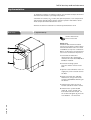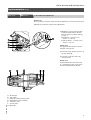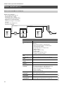
1
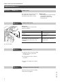
Service instructions
for heating engineers
Vitoflame 200
Oil pressure jet burner (type VEK)
H up to 40 kW with oil pre-heater
H from 50 kW without oil pre-heater
for Vitola 100, Vitola 111, Vitola 200 and Vitola 222
See: Applicability, page 2.
VITOFLAME 200
Vitoflame 200 oil burner
mounted on a Vitola 200
5692 437
GB
9/2001
File in: Service folder
General Information
Safety instructions
Please follow these safety instructions closely to avoid the risk of injury to individuals and damage to property.
Work on the equipment
The installation, initial start-up,
commissioning, maintenance and
repairs must only be carried out by a
competent person (heating
engineer/service contractors) (see
EN 50 110, part 1, and VDE 1000,
part 10) (GB: British Standards and
I.E.E. regulations).
Before working on the
equipment/heating system, isolate
the system from the mains electricity
supply, e.g. by removing a separate
mains fuse or by means of a mains
electrical isolator, and safeguard
against unauthorised re-connection.
Repair work
This is not permitted on components
with safety functions.
Use only original Viessmann spare
parts or equivalent parts approved
by Viessmann.
Initial start-up
This must be performed by the
installer or a designated
commissioning engineer; all
readings must be recorded in a
commissioning/service report.
Instructing the system user
The system builder must hand the
operating instructions to the system
user and instruct him/her in its
functions and controls.
This indicates a reference to
other instructions which
must be observed.
Disconnection must be carried out
by means of an isolating device
which simultaneously isolates all
non-earthed conductors with at least
3 mm contact separation.
Work requiring the control unit to be
opened must not subject internal
components to electrostatic
discharges.
Applicability
Applicable to burners from serial no.:
7143148 k 00000 kkk,
7143149 k 00000 kkk,
7143150 k 00000 kkk,
7143151 k 00000 kkk,
7143152 k 00000 kkk,
7143153 k 00000 kkk,
7143154 k 00000 kkk,
7143155 k 00000 kkk
Operating and service documents
H Keep the part designated for the
heating engineer.
2
GB
H Hand the system user section to
the user for safekeeping.
2. File all parts lists, operating and
service instructions in the folder
and hand this over to the system
user.
5692 437
1. Complete and detach the
customer registration card:
Contents
Page
General information
Safety instructions
Applicability
............................................................................................
2
..........................................................................................................
2
Operating and service documents
Initial start-up
and maintenance
.............................................................
2
..........................................................................................
4
..................................................................................................
5
Procedure overview
Implementation
Burner control unit
Troubleshooting
Procedure overview
Diagnosis
Additional information
............................................................................................
..........................................................................................
18
...............................................................................................................
19
Specification
.........................................................................................................
Approximate values for burner settings
22
......................................................................................
23
...................................................................................................
25
.................................................................................................................
27
Wiring diagram
Maintenance report
..........................................................................................
31
........................................................................................................................
32
5692 437
GB
Index
21
.................................................
Component overview
Parts list
14
3
Initial start-up and maintenance
Procedure overview
Initial start-up steps
Maintenance steps
1. System start-up
M
M
M
M
M
M
M
M
M
M
M
M
M
M
M
M
M
Page
5
...................................................................................
Page
6
.....................................................................................................................
Page
7
...................................................................................................................................................
Page
8
Page
8
Page
8
....................................................................................................
Page
8
....................................................................................................................................
Page
9
.............................................................................................................
Page
9
.................................................................................................................
Page
9
............................................................................................................................................
2. Oil pressure adjustment and vacuum check
3. Air volume fine adjustment
4. Burner check
5. Flame monitor check
..................................................................................................................................
6. Heating system shut-down
.....................................................................................................................
7. Checking the electrical connections
8. Cleaning the burner
9. Checking the blast tube fixings
10. Checking the impeller fixings
11. Nozzle replacement
....................................................................................................................................
12. Checking and adjusting the ignition electrodes
13. Installing the burner on the burner housing
............................................................................
Page 11
...................................................................................
Page 11
14. Cleaning or, if necessary, replacing the oil pump filter
..............................................................
Page 12
..............................................................................................................
Page 12
............................................................................................................................................
Page 13
15. Pre-filter element replacement
16. System start-up
Page 10
17. Checking all oil pipes and connections for leaks
18. Re-checking the burner
..........................................................................
Page 13
.............................................................................................................................
Page 13
5692 437
GB
I
I
I
I
4
Initial start-up and maintenance
Implementation
To obtain the optimum combustion values, it is essential to adjust the burner
with the boiler heated to operating temperature.
Check the CO content, CO2 content, flue gas temperature, room temperature
and chimney draught after at least 2 minutes operation and at 60 °C boiler
water temperature with fitted burner hood.
Remove the burner hood before commencing maintenance work.
Initial start-up
1. System start-up
Service instructions
boiler control unit
Please note:
Vitoflame 200 oil burners feature
very good combustion values which
are achieved without the use of fuel
oil additives to improve combustion.
We do not therefore recommend the
use of such combustion improvers.
1. Check that the blast tube
attachment or the combustion
chamber liner (for Vitola 200, 40 to
63 kW) is installed.
2. Check the heating system
pressure and the oil level in the
tank.
3. Open the shut-off valves in the oil
supply line, on the oil tank and on
the filter.
4. Fill the oil suction line and filter
with fuel oil, using a manual oil
suction pump before switching on
the burner.
5. Switch on the mains electrical
isolator (outside the boiler room).
5692 437
GB
6. Switch on the system On/Off
switch B on the control unit.
If the fault indicator lamp A on
the control unit lights up, press the
reset button C on the burner.
5
Initial start-up and maintenance
Implementation (Cont.)
Initial start-up
Maintenance
2. Oil pressure adjustment and vacuum check
Please note:
The oil pressure is preset at the factory. Re-adjust the oil pressure if necessary.
1. Isolate the mains electricity
supply and take measures to
prevent re-connection.
2. Unscrew plug ”P” A from the
oil pump.
3. Unscrew plug ”V” B from the
oil pump.
Danfoss oil pump, type BFP 21
4. Insert a pressure gauge (range
0-25 bar) and a vacuum gauge
(range 0-1 bar); seal the gauges
only with copper / aluminium
gaskets or O-rings.
Please note:
Do not use tape to seal these
joints.
5. Start up the burner.
The solenoid valve opens.
6. Read off the oil and vacuum
pressures of the pump on the
relevant gauges (the vacuum
should be max. 0.35 bar given a
head of 3 m between the oil
pump and the bottom of the
tank).
Where the vacuum measures
higher than 0.35 bar, check the
filter for cleanliness or the pipe
run.
7. If necessary, set the oil pressure
on the oil pump pressure setting
screw C (for Danfoss pumps:
depending on the model either on
the front or the side).
Turning clockwise → pressure
increases
Turning anti-clockwise → pressure
decreases.
Please note:
For approximate values for burner
settings, see page 22.
8. Check the emission values after
checking the oil pressure.
9. Isolate the mains electricity
supply and take measures to
prevent re-connection.
Suntec oil pump, type AL 35
12. Start up the burner and check the
plugs for leaks.
6
Please note:
Check the plug seal rings for
possible damage and replace,
if necessary.
5692 437
11. Insert plugs ”P” A and ”V” B.
GB
10. Remove the pressure and
vacuum gauges.
Initial start-up and maintenance
Implementation (Cont.)
Initial start-up
Maintenance
3. Air volume fine adjustment
Please note:
The oil pressure is preset at the factory. Re-adjust the air volume if necessary.
Starting up the burner requires fine adjustment.
1. Modify the sensor plate position
inside the blast tube; to do this,
turn the nozzle assembly setting
screw C:
H Clockwise → greater cross
section → more air,
H anti-clockwise → smaller cross
section → less air.
Please note:
For approximate values for burner
settings, see page 22.
2. Check the static burner pressure at
the test nipple B.
3. Check the emission values by
measurement.
A Air damper
B Test nipple
C Nozzle assembly setting screw
D Adjustable nozzle assembly
E Terminal screw
F Sensor plate
G Blast tube
5692 437
GB
Please note:
Do not slacken the terminal screw
E, otherwise the zero point of the
nozzle assembly will be altered.
7
Initial start-up and maintenance
Implementation (Cont.)
Initial start-up
Maintenance
4. Burner check
Record all test values in the order of
the maintenance report on the
penultimate page of this manual.
Maintenance
Please note:
The flue-gas pipe must be sealed
on the boiler connection.
Infiltrating air leads to false
measurements.
5. Flame monitor check
Please note:
The flicker detector is preset at the
factory to setting 4.
Safety check
Response
Burner start with darkened flame
monitor.
Fault shut-down at the end of
the safety period.
Burner start with flame monitor lit from
an outside source.
Fault shut-down not later than
after 40 sec.
Burner operation with simulated flame
interruption: cover the flame monitor
during operation and leave in this
condition.
Restart followed by fault
shut-down at the end of the
safety period.
B Flame monitor
Maintenance
6. System shut-down
1. Isolate the mains electricity supply
and take measures to prevent
re-connection.
2. Pull the plug-connector fA from
the burner.
3. Close the oil supply line (oil filter
valve).
7. Checking the electrical connections
5692 437
Check the plug-connections and the
cable bushes for tight fit.
GB
Maintenance
8
Initial start-up and maintenance
Implementation (Cont.)
Maintenance
8. Cleaning the burner
1. Set the burner to maintenance.
2. Clean the housing and the blast
tube, the sensor plate A, the
ignition electrodes B, the flame
monitor C and the fan D.
Maintenance
Cleaning the combustion
chamber and hot gas flues,
see boiler service
instructions.
9. Checking the blast tube fixings
See maintenance item 8.
Maintenance
10. Checking the impeller fixings
5692 437
GB
See maintenance item 8.
9
Initial start-up and maintenance
Implementation (Cont.)
Maintenance
11. Nozzle replacement
1. Plug the burner chassis with
nozzle assembly pointing upwards
onto the burner housing.
Please note:
This avoids air bubbles being
created when replacing nozzles.
15 to 33 kW
2. Release fixing screw C by two
full turns.
3. Remove sensor plate A from the
nozzle assembly.
4. Unscrew nozzle F (whilst holding
the nozzle assembly).
5. Insert the replacement nozzle
(whilst holding the nozzle
assembly).
Please note:
For make and type of nozzle, see
approximate values for burner
settings, page 22.
40 kW
6. Only for 15 to 33 kW:
Check seal ring B on deflector D
of the sensor plate and apply
instrument grease; replace the
seal ring if necessary.
7. Push sensor plate A onto the
nozzle assembly up to the
end-stop of the oil pre-heater and
re-tighten fixing screw C.
Please note:
Only for 15 to 33 kW:
Also fit the spacer E behind the
sensor plate.
5692 437
GB
50 and 63 kW
10
Initial start-up and maintenance
Implementation (Cont.)
Maintenance
12. Checking and adjusting the ignition electrodes
Check ignition electrodes A for
wear, cleanliness and dimensions
(see fig.) and replace if necessary.
1.5+0.3
15 to 33 kW
1.5+0.3
Maintenance
13. Install the burner on the burner housing
5692 437
GB
40 to 63 kW
11
Initial start-up and maintenance
Implementation (Cont.)
Maintenance
14. Cleaning or, if necessary, replacing the oil pump filter
Danfoss oil pump
type BFP 21
1. Unscrew filter plug A from the
pump cover with a 4 mm Allen
key.
2. Remove the plug A with cartridge
filter C.
3. Carefully separate filter C from
plug A using a screwdriver.
4. Change O-ring B on plug A.
5. Push the new filter onto plug A.
6. Insert the plug and filter into the
oil pump.
Suntec oil pump, type AL 35
1. Unscrew the four screws from the
pump housing and remove the
cover.
2. Depending on the level of
contamination, clean oil pump
filter A with clean fuel oil or
replace the filter.
3. During re-assembly, replace flat
gasket B of cover D and plug
O-rings C with new parts.
Maintenance
15. Replacing the pre-filter elements
5692 437
GB
Check the O-ring sealing the filter
cup for possible damage and
replace, if necessary.
12
Initial start-up and maintenance
Implementation (Cont.)
Maintenance
16. System start-up
1. Open the oil filter valve.
2. Switch on the mains electrical
isolator (outside the boiler room).
3. Switch on the system On/Off
switch on the control unit.
Maintenance
17. Checking the oil pipes and connections for leaks
The presence of air bubbles in the
pre-filter is a sign of a leak in the
suction line. Check oil pipes and
connections on the oil tanks. Leaks
will cause the fuel oil to continue to
be injected (run-on) and produce
soot deposits on the sensor plate.
Maintenance
18. Re-checking the burner values
Please note:
The flue-gas pipe must be sealed at
the boiler connection. Infiltrating air
leads to false measurements.
5692 437
GB
Record all test values in the order of
the maintenance report on the
penultimate page of this manual.
13
Initial start-up and maintenance
Burner control unit
You may use the following burner
control units with this burner:
Burner control unit LOA 14.171B2V
H For operating sequence, see p. 25.
H Sensor current:
– min. requirement 50 µA
– max. permissible without flame
5.5 µA
H Undervoltage
When the mains voltage falls
below 165 V~, the burner will be
prevented from starting or the oil
flow will be interrupted;
simultaneously the system will be
initiating a fault shut-down.
H Fault setting
A lamp in the reset button also
indicates the fault shut-down of the
burner control unit.
Burner control unit LMO 14.113A2
H For operating sequence see page 25. H Controlled intermittened operation
After a maximum of 24 hours
H Sensor current:
non-stop operation, the burner
– min. requirement 40 µA
control unit implements an
– max. permissible without flame
automatic safety shut-down with
5.5 µA
subsequent re-start.
H Control sequence in case of faults
The fuel valve outputs and the
ignition system are immediately shut
down (< 1 sec.) if the system shuts
down because of faults.
H Undervoltage
If the mains voltage falls below
165 V~, the burner control unit
initiates a safety shut-down.
The system re-starts when the mains
voltage rises again above approx.
175 V~.
Cause
Response
After mains power failure.
Re-start
After falling below the undervoltage level.
Re-start
In case of premature, faulty flame signal during the
pre-flush time t1.
Fault shut-down at the end of the pre-flush
time t1.
In case of premature, faulty flame signal during the
oil pre-heat time t0.
Starting will be inhibited after a fault
shut-down of a maximum of 40 sec.
If the burner does not light within the safety limit t2.
Fault shut-down at the end of the safety period
t2.
If the flame fails during operation.
Max. 3 start repeats, then fault shut-down.
No heating or oil pre-heater enabling within 10 min.
Fault shut-down.
H Resetting the burner control unit
The system can be reset
immediately after a fault
shut-down.
Hold down the reset button for
approx. 1 sec. (< 3 sec.).
H Repeat limitation
Up to a max. of three re-ignition
attempts can be made if the flame
has failed. The fourth flame failure
during operation triggers a fault
shut-down. The repeat count
always starts with every controlled
14
switch-on (through temperature or
pressure regulators, thermostat or
pressure limiters or high limit
safety cut-outs).
GB
H Firing sequence
If the flame fails within the safety
period, the system re-ignites up to
the end of the max. safety period.
This allows several firing attempts
within the safety period, see
program sequence on page 25.
5692 437
H Fault shut-down
After a fault shut-down, the burner
control unit remains locked out
(non-modifiable fault shut-down)
and the red lamp lights up.
This state also remains after a
mains power supply failure.
Initial start-up and maintenance
Burner control unit (Cont.)
Burner control unit LMO 14.113A2 (Cont.)
H Operation
The reset button ET is
the central control
element for resetting
and for activating and
deactivating the
diagnostic system.
The multi-coloured LED
red
is the central display
yellow element for the visual
green diagnosis as well as the
interface diagnosis.
Both elements (ET and LED) are
located under the clear cover of the
reset button.
Two diagnostic options are available:
1. Visual diagnosis
Operational display or fault cause
diagnosis
2. The interface diagnosis
This will not be described here.
During normal operation, the various
conditions are indicated by colour
code, acc. to the colour code table
below.
By pressing the reset button > 3 sec.
you can also activate the interface
diagnosis. If you accidentally
activated the interface diagnosis,
which can be recognised by the
weakly flickering red signal lamp,
you can deactivate this option by
pressing the reset button again.
The correct adjustment timing will
be indicated by a yellow lamp
impulse.
H Operational display
Colour code table
Condition
Colour code
Colour
Oil pre-heater active, oil pre-heat
time t0
\\\\\\\\\\\
yellow
Ignition phase, ignition activated
\0\0\0\0\0\0\
yellow off
Operation, flame OK
jjjjjjjjjjjj
green
Operation, poor flame
j0j0j0j0j0j
green off
Undervoltage
\♦\♦\♦\♦\♦\
yellow red
Fault, alarm
♦♦♦♦♦♦♦♦♦♦♦
red
Fault code output, see fault code
table on page 16
♦0 ♦0 ♦0 ♦0 ♦0
red off
External light before burner start
j♦j♦j♦j♦j♦j
green red
Interface diagnosis
♦♦♦♦♦♦♦♦♦♦♦♦♦♦
red flickering light
5692 437
GB
Legend:
0 off
\ yellow
j
green
♦
red
15
Initial start-up and maintenance
Burner control unit (Cont.)
Burner control unit LMO 14.113A2 (Cont.)
H Fault cause diagnosis
The red signal lamp stays on
permanently after a fault
shut-down. In this condition, you
can activate the visual fault cause
diagnosis acc. to the fault code
table by pressing the reset button
> 3 secs.
The fault cause diagnosis is
activated as follows:
1 sec. (<3secs.)
Fault setting
1 sec. (<3secs.)
>3 secs.
Fault setting
Visual diagnosis
Interface diagnosis
flashes
on
flickers
Reset
fault code table
>3 secs.
16
Flash code
Possible cause
2 × flashing
DD
The flame is not established at the end of the safety
period
– fuel valves faulty or contaminated
– flame monitor faulty or contaminated
– solenoid valve faulty
– oil pump faulty (no oil pressure)
– Motor faulty
– plug-in coupler faulty
– nozzle faulty
– poor burner setting, no fuel
– ignition equipment faulty
3 × flashing
DDD
N/A
4 × flashing
DDDD
External light during the pre-purge phase.
5 × flashing
DDDDD
N/A
6 × flashing
DDDDDD
N/A
7 × flashing
DDDDDDD
Flame fails too often during operation
(re-start limit after the 3rd control demand)
– fuel valves faulty or contaminated
– flame monitor faulty or contaminated
– poor oil supply
– poor burner setting
8 × flashing
DDDDDDDD
Time monitor oil pre-heater
(not enabled after 10 min.)
9 × flashing
DDDDDDDDD
N/A
GB
10 × flashing
DDDDDDDDDD
Faulty electrical contact, wires L1 and N
interchanged or faulty burner control unit.
5692 437
Fault code table
Initial start-up and maintenance
Burner control unit (Cont.)
Burner control unit LMO 14.113A2 (Cont.)
During the fault cause diagnosis, all control outputs are at zero volt.
H The burner remains switched off.
H The fault signal at terminal 10 is switched on.
5692 437
GB
You exit the fault cause diagnosis and re-start the burner by pressing reset.
Hold down the reset button for approx. 1 sec. (< 3 secs.).
17
Troubleshooting
Procedure overview
Diagnosis
1. Establish fault/ascertain system behaviour.
2. Look for the corresponding fault cause in the diagnosis tables.
3. Establish the action required from the table.
4. Correct the fault.
5692 437
GB
Remedy
18
Troubleshooting
Diagnosis
Fault/behaviour of the system
Cause of fault
Check
Burner does not start (without fault
display), fault lamp does not
illuminate.
No voltage.
Check fuse or connector aBÖ in the
control unit or plug-in terminal
block, electrical connections, setting
of heating system On/Off switch on
the control unit and the mains
electrical isolator.
High limit safety cut-out activated.
Press the reset button on the boiler
control unit.
Motor faulty.
Replace the motor.
Coupling between motor and oil
pump faulty.
Replace the coupling.
Oil pump seized or stiff.
Clean or, if necessary, replace oil
pump.
Ignition electrodes poorly adjusted.
Adjust correctly (see page 11).
Ignition electrodes damp and
contaminated.
Clean the ignition electrode block.
Ignition electrode insulation cracked.
Replace the ignition electrode block.
Ignition transformer faulty.
Replace the ignition transformer.
Ignition cable faulty.
Replace the ignition cable.
Pump does not feed oil.
Install pressure and vacuum gauges
on the pump and check the pressure
build-up (see the following
paragraph).
Shut-off valves closed at the filter or
in the oil pipe.
Open the valves.
Filter blocked.
Clean the filter (pre-filter and pump
filter).
Coupling between motor and pump
faulty.
Replace the coupling.
Leak in the suction line or filter cup.
Tighten the connections.
Check oil pipes for leaks and seal if
necessary.
Oil flow and return hoses
interchanged.
Connect correctly acc. to the
instructions on the pump.
Vacuum in suction line too high
(higher than 0.35 bar).
Check cross-section of oil pipes.
Replace the filter. Check the external
oil valve.
External oil valve faulty.
Check and, if necessary, replace the
external oil valve.
Solenoid coil faulty.
Replace the solenoid coil.
Oil pump faulty.
Replace the oil pump.
Nozzle blocked.
Replace the nozzle.
Flame monitor faulty.
Replace the flame monitor.
Burner does not start up (with fault
display).
Burner starts up,
p, but no flame is
formed.
Pump does not feed oil.
5692 437
GB
Burner starts up,
p, but no oil is
injected.
19
Troubleshooting
Diagnosis (Cont.)
Fault/behaviour of the system
Cause of fault
Check
Burner starts up
p and flame is
formed, but the burner cuts out after
the safety time expires.
Flame monitor contaminated.
Clean the flame monitor.
Flame monitor receives insufficient
light.
Clean the sensor plate.
Flame monitor faulty.
Replace the flame monitor.
Burner control unit faulty.
Replace the burner control unit.
Blast tube beginning to coke up.
Clean the blast tube.
Air in the suction line.
Seal the line and filter.
Nozzle faulty.
Replace the nozzle.
Burner incorrectly adjusted.
Re-instate factory pre-set values
(see page 22).
Sensor plate contaminated.
Clean the sensor plate.
Flame monitor contaminated.
Clean the flame monitor.
Sensor plate contaminated.
Clean the sensor plate.
Nozzle contaminated.
Replace the nozzle.
Fan pressure too high.
Check the fan pressure at the test
nipple on top of the fan housing
(U-shaped pressure gauge).
Set the air damper or the nozzle
assembly so that the lower value of
the static burner pressure (see the
”approximate values for burner
settings”, page 22) is not exceeded.
Oil consumption too high.
Correctly adjust the oil pressure
(see page 22).
Too little or too much air.
Correct the setting.
Check and clean the impeller.
Check the ventilation of the boiler
room.
Insufficient flue pressure.
Check stack and flue gas baffles.
Nozzle faulty.
Replace the nozzle or install the
correct nozzle (see page 22).
Blast tube attachment or
combustion chamber liner missing
or faulty.
Fit or replace the blast tube
attachment or combustion chamber
liner.
Incorrect setting.
Check setting (see page 22).
Infiltrating air.
Seal flue gas pipe at boiler
connection.
Tighten the fixing screws on the
combustion chamber cover and the
flue gas cover.
Oil consumption too high.
Match the oil flow to the rated
output of the boiler.
Boiler contaminated.
Clean boiler and correct burner
settings.
Flame extinguishes
g
during
g
operation.
Ignition switches on during
operation.
ti
Flame pulsates.
Burner sooty.
CO2 content too low.
5692 437
GB
Flue gas temperature too high.
20
Additional information
Specification
Rated output
kW
Type of burner
15
18
22
27
33
40
50
63
VEKI-1
VEKI-1
VEKI-1
VEKI-1
VEKI-1
VEKI-2
VEKII-1
VEKII-2
Type test no.
acc. to DIN EN 267
5G971/2001S
5G972/2001S
Voltage
V
230
Frequency
Hz
50
Motor speed
rpm
Version
Oil pump output
2800
single stage
litres/hr.
e
5692 437
GB
Connections
Oil hose flow and
R (female thread)
return (included in the
delivery).
45
21
Additional information
Approximate values for burner settings
Please note:
Check whether the service instructions are valid for the boiler concerned (see: Applicability, page 2 and serial no. on
the burner type plate).
Rated output
kW
Oil burner nozzle
Make
Fluidics*1
Type
Make
Danfoss
Oil pressure
approx.*2
Oil flow rate
15
18
22
27
33
40
50
63
60°HF/
70°HF/
0.5
––
60°HF
45°SF
60°S
80°H
0.6
––
60°HF/
45°HF
0.75
––
––
Gph
Type
60°HF/
70°HF/
0.4
––
1.0
––
1.1
––
1.5
––
Gph
––
––
/––
––
––
45°H/
45°S/
0.85
––
––
––
bar
9.0
9.0
9.0
8.5
9.0
10.0
11.5
10.5
kg/hr.
litres/hr.
1.4
1.6
1.7
2.0
2.0
2.4
2.5
2.9
3.0
3.6
3.7
4.3
4.6
5.4
5.8
6.8
7.5
8.0
8.5
10.0
13.5
16.5
17.0
25.0
3.0
3.0
5.0
8.0
10.0
8.0
10.0
14.0
3.2 - 3.6
3.2 - 3.6
3.2 - 3.6
3.0 - 3.3
2.5 - 3.0
2.5 - 3.0
0
0
0
0
0
Air damper setting
Air damper position
(see page 7)
Nozzle assembly setting
Setting screw position
(see page 7)
mm
Static burner pressure*3 mbar
Test nipple location
(see page 7)
Aluminium deflector
of sensor plate
Number of plugs
remaining in the deflector
5
3.2 - 3.7 2.5 - 3.0
0
0
*1The
requirements laid down for the certificate of environmental excellence were verified only with the nozzles shown.
to nozzle tolerances and varying oil characteristics, the oil pressure may vary from that indicated by the values shown.
*3To check the burner settings.
5692 437
GB
*2Due
22
5692 437
GB
Platzhalter Bauteilübersicht
23
5692 437
GB
Pl a tzh a l te r
24
5692 437
GB
Pl a tzh a l te r Stro m l a u fp l a n
25
5692 437
GB
Pl a tzh a l te r
26
5692 437
GB
Pl a tzh a l te r Ei n ze l te i l l i s te
27
5692 437
GB
Pl a tzh a l te r
28
5692 437
GB
Pl a tzh a l te r
29
5692 437
GB
Pl a tzh a l te r
30
GB
bar
bar
actual
after maintenance
% by vol
set
%
set
mm
mm
actual
set
Air damper
setting
mm
mm
hPa (1hPa=1 mbar)
actual
Nozzle assembly setting set
Draught (at the actual
boiler)
set
hPa (1hPa=1 mbar)
%
actual
Flue gas loss
°C
Flue gas temp- actual
erature (gross) set
°C
% by vol
actual
Oxygen
content O2
% by vol
set
% by vol
bar
set
actual
bar
actual
Carbon dioxide actual
content CO2
set
Soot indicator
Vacuum
Oil pressure
5692 437
By:
Initial start-up
Date:
Maintenance/
Service
Date:
By:
Maintenance/
Service
Date:
By:
By:
Maintenance/
Service
Date:
By:
Maintenance/
Service
Date:
By:
Maintenance/
Service
Date:
Additional information
Maintenance Report
31
Additional information
Index
B
Blast tube fixings - checking, 9
Burner - cleaning, 9
Burner control unit, 14
Burner - installation on burner
housing, 11
Burner settings - approximate
values, 22
Burner values - checking, 8
C
Component overview, 23
D
Diagnosis, 18, 19
I
Ignition electrodes - settings, 11
Ignition electrodes - checking, 11
Impeller fixings - checking, 9
L
Leaks - checking, 13
M
Maintenance report, 31
N
Nozzle replacement, 10
S
Safety instructions, 2
Shut-down - heating system, 8
Specification, 21
Start-up - heating system, 5, 13
T
Troubleshooting, 18
V
Vacuum - checking, 6
W
Wiring diagram, 25
Printed on environmentally friendly,
chlorine-free bleached paper.
A
Air volume re-adjustment, 7
Applicability, 2
O
Oil connections, 13
Oil lines, 13
Oil pressure adjustment, 6
Oil pump filter cleaning and
replacement, 12
E
Electrical connections - checking, 8
Viessmann Limited
Hortonwood 32, Telford
Shropshire, TF1 4EU, GB
Tel:
(01952) 670261
Fax:
(01952) 670103
32
Subject to technical modifications.
GB
Viessmann Werke GmbH&Co
D-35107 Allendorf
Tel:
(06452) 70-0
Fax:
(06452) 70-2780
www.viessmann.de
5692 437
F
Flame monitor - checking, 8
P
Parts list, 27
Pre-filter element replacement, 12
Procedure overview, 4, 18
5692 437 GB
A Air regulating valve
B Flame monitor
(flicker detector)
C Burner control unit
D Reset button
E Connection panel
F Return pipe
G Suction pipe
Component overview
H Fan motor
K Oil pump
L Solenoid valve
M Nozzle assembly setscrew
N Oil pipe
O Ignition transformer
P Ignition cable
R Ignition electrode
S Blast tube
T Blast tube attachment
U Sensor plate
V Oil burner nozzle
W Nozzle assembly with oil
pre-heater
X Impeller
Y Burner housing
23/24
Additional information
25/26
Supply
(on-site)
External
fault lamp
Control unit
components
Wiring diagram
Operating lamp
(plug-in terminals)
Burner control unit
Additional information
Oil pre-heater
15-40 kW
Solenoid
valve for
external
connection
via a
separate
adapter
Burner
motor
Start-up function sequence
Flame monitor
t3
approx 13s
Ignition
transformer
Operating lamp
or external
hours-run meter
(control unit)
Oil pump
solenoid valve
Pre-ignition time
Safety time
Pre-flush time
10s
3s
approx 15s
max
approx 16s
t3n Re-ignition time if approx
flame is established
t2
2) Depending on the temperature of the
fuel oil supplied
t3
t1
10s
max
2mins
LMO 14.113
Oil pre-heat time 2) to
Control program
t0
approx 13s
Oil pre-heater
Pre-ignition time
t2
t3n Re-ignition time if approx 15s
flame is established
Safety time
t1
Ignition
transformer
2mins
LOA X4 . . . .
Burner motor
Pre-flush time
t0
Oil pre-heat time 2) to
Control program
Solenoid Valve
Flame monitor
Start of oil pre-heat time
Start-up
Timing of flame
being established
Operating position
Controlled shut-down
Please note:
This wiring diagram only applies in
conjunction with Viessmann
products.
of assembly modules and
accessories via system plug-in
connector fA (e.g. KNL, extension
cable, etc.).
2) Connection of external safety
equipment via system plug-in
connector aBÖ.
3) Connection of external control
off-switch via system plug-in connector
aBÖ.
4) Connection for external burner ON.
black
brown
blue
red
1) Connection
BK
BN
BU
RD
Colour coding conforming to
DIN/IEC 757
Burner plug on the
control unit
F1.1
Fuse in the control unit
F6
High limit safety cut-out
F7
Thermostat
S1
Mains electrical switch
S2
Test button
K1
Burner relay
1 - qW Plug-in terminals on the
oil burner control unit
fA
C
D
A‘
A
B
Legend
5692 437 GB
5692 437 GB
Wear parts
008 Plug-in coupler
016 Combustion chamber liner
40-63 kW
017 Blast tube attachment 15-33 kW
A Type plate
080 Small parts comprising:
80a Locking spigot Allen
head 4 mm
80b Plug spigot compression spring
80c Plug spigot lockwasher
80d Cheese-head screw M 5 × 10
80e Cheese-head screw M 5 × 45
thread length 30 mm
80f Cheese-head screw M 6 × 20
80g Cable clamp
80h Cheese-head screw M 6 × 30
80i Headless screw M 6 × 10
80k Machine screw A M 4 × 10-H
80l Spring washer A 5
80m O ring 19 - 2.5 VIOR
80o Straight connector
80p Gasket A 10 × 14 × 1.5
80r Cheese-head screw M 5 × 12
80s Spacer
Parts
001 Blast tube
002 Sealing plate ∅ 182 × 30 × 3
004 Burner housing
005 Profile stud
006 Fan motor
007 Oil pipe
009 Burner hood
010 Insulation mat with adhesive
011 Suppressor extension
012 Oil burner control unit
013 Electronic ignition
014 Burner flange
018 Setting: nozzle assembly
024 Air damper
028 Burner control unit plug-in base
029 Flame monitor
049 Burner hood latches
When ordering spare parts:
Quote the type and serial no. (see
type plate) and the item no. of the
required part (as per parts list).
You can obtain common parts from
your local supplier.
Parts list
27/28
Additional information
29/30
Parts (not shown)
071 Installation instructions
072 Service instructions
079 Burner pack
Wear parts
044 Ignition electrode block
045 Nozzle
046 Spare parts set for Suntec oil
pump
047 Cartridge filter for Danfoss oil
pump
080 Small parts comprising:
80a Locking spigot Allen
head 4 mm
80b Plug spigot compression spring
80c Plug spigot lockwasher
80d Cheese-head screw M 5 × 10
80e Cheese-head screw M 5 × 45
thread length 30 mm
80f Cheese-head screw M 6 × 20
80g Cable clamp
80h Cheese-head screw M 6 × 30
80i Headless screw M 6 × 10
80k Machine screw A M 4 × 10-H
80l Spring washer A 5
80m O ring 19 - 2.5 VIOR
80o Straight connector
80p Gasket A 10 × 14 × 1.5
80r Cheese-head screw M 5 × 12
80s Spacer
Parts
019 Impeller
020 Oil hose - flow
021 Oil hose - return
027 Sensor plate
030 Nozzle assembly with oil
pre-heater
032 O-ring 54 × 3
033 Solenoid valve coil for Suntec
oil pump
034 Solenoid valve nut for
Suntec oil pump
038 Suntec oil pump
039 Solenoid valve core for Suntec
oil pump
040 Danfoss oil pump
041 Solenoid valve coil for Danfoss
oil pump
042 Ignition cables (set)
Parts list (Cont.)
Additional information
020
040
041
038
021
047
80p
80o
039
033
034
046
019
80c
030
042
80s
045
80m
032
044
80d
80l
027
80d
5692 437 GB