1
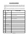
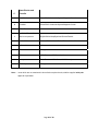
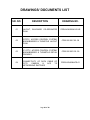
TECHNICAL
SURVEILLANCE
SPECIFICATIONS
SYSTEM,
FOR
ACCESS
IP
CCTV
CONTROL
SYSTEM
(ACS), BOOM-BARRIER AND TURNSTILE.
--------------------------------------------------------------------------------------- GENERAL SITE CONDITIONS:
Max. Ambient Temperature
Min. Ambient Temperature
:
:
45 degree C and 50 degree C ( designed)
4 degree C
Max. R H
:
97%
Min. R H
:
30%
Altitude
:
1000 meters
INSPECTION OF SITE :
The bidder should inspect and examine the site and its surrounding and shall satisfy as to the
nature of the ground and sub soil, the quantities and nature of work, materials necessary for
completion of the work and their availability, means of access to site and in general to obtain all
necessary information as to risks, contingencies and other circumstances which may influence or
affect his offer. No extra claim consequent on any misunderstanding or otherwise shall be
allowed.
REFERENCE DRAWINGS/DOCUMENTS:
(1) LAYOUT‐BUILDINGS CO‐ORDINATES PLAN ( DRG NO. CDRI/LKW/499/A1W‐043‐R03) (2) IPCCTV, ACCESS CONTROL SYSTEM, BOOM‐BARRIER & TURNSTILE LAYOUT PLAN ( DRG NO. CDRI 000 00 P 02 ‐00)
(3) IP CCTV, ACCESS CONTROL SYSTEM, BOOM‐BARRIER & TURNSTILE DETAIL DRAWING ( DRG NO. CDRI 000 00 P 03 ‐00)
(4) CONNECTIVITY OF DATA CABLE OF CCTV CAMERA & ACS TO NETWORKING SWITCHES (DRG NO.CDRI/LKW/499/ACS‐01) Page 1 of 30 DESIGN CONCEPT & SCOPE OF WORK :
1) IP CCTV SURVEILLANCE SYSTEM
(i) DESIGN CONCEPT:
•
•
•
•
•
•
•
•
•
•
•
•
The entire IP surveillance system is designed to control and monitor the different blocks of the
CDRI campus. All the corridors shall have IP Fixed dome camera to monitor the connecting
corridors
There are three types of cameras shall be installed to monitor the movement of the people as
follows:
- IP fixed dome camera indoor type
- IP PTZ camera outdoor type
- IP fixed box camera outdoor type
IP fixed dome camera shall be installed at the entrances and connecting corridors of the main
buildings like laboratories, administration block, computer hub, special equipment and lab
engineering services, library, auditorium, chemical storage and animal house.
IP PTZ camera shall be mounted on the pole at different locations for outside surveillance
purpose.
IP fixed box camera shall be mounted on the pole at all boom-barrier and turnstile locations to
monitor the vehicles and pedestrians passing by there.
All cameras shall be true IP camera.
All outdoor cameras shall be in IP-66 housing.
All outdoor items for cameras like JBs, power supply, media convertor etc. shall be in water poof
and dust proof housing.
Purchaser’s LAN network being laid by third party would be utilized to extend the IP CCTV
connectivity to central server
All CCTV cameras shall shall have connectivity to non- PoE port of purchaser’s networking
switches on LAN.
UPS Power supply for each camera.
Tentative locations of cameras are indicated in the IP CCTV, ACS , Boom Barriers and Turnstiles
layout drawing enclosed with this tender
(ii) SCOPE OF WORK:
•
•
•
•
•
•
Supply, installation, testing and commissioning high quality fast-acting IP CCTV surveillance
system along with power supply, power distribution and required accessories in different blocks of
CDRI campus as indicated in BOQ.
The entire system shall be as per BOQ, drawings and technical specifications enclosed with
tender documents.
The price coated by the vendor should include all the expenses incurred in commissioning of all
cameras with power supply, accessories and other devices complete with software.
The CCTV surveillance system should consist of IP Fixed dome cameras (indoor type), PTZ &
fixed box cameras (outdoor type), software, server, power supply and cables.
Video management software shall offer both video stream management and video stream
storage management. Recording frame rate and resolution in respect of individual channel shall
be programmable.
The system is presently designed for 45 cameras where as not limited to the same and scalable
upto unlimited cameras if required in the future.
Page 2 of 30 •
•
•
•
•
Provide supervisory specialists and technicians at the job to assist in all phases of system
installation, start up and commissioning.
Cat 6cable/fiber cable connectivity with all required hardware upto purchaser’s networking
switches of LAN, locations of networking switches in CDRI campus are indicated in the list.
enclosed with this tender documents.
230 volts AC Power supply distribution from UPS to each location of cameras along with DBs
,JBs, cabling work etc. with required accessories.
Power supply unit as required for camers.
Integrated testing and commissioning of CCTV system on LAN being provided by the third party
in CDRI campus.
•
Training & handing over of all materials, equipment and appliances.
•
Any other items/accessories required for installation, testing and commissioning of CCTV
system.
No extra cost shall be paid for miscellaneous items if required to complete the work as per the
design concept.
•
Page 3 of 30 2) ACCESS CONTROL SYSTEM (ACS):
(i) DESIGN CONCEPT
•
Access Control System is designed for the entrances and corridors of main buildings of CDRI
campus as follows:
- Entrance of the Administration block
- Entrance of the Computer hub
- Front and back entrances of the laboratories and connecting corridors
- Entrance of the Special Equipment and lab engineering services
- Entrance of the Chemical Storage
- Front and back entrance of the Animal House
- Hospital dispensary for time attendance
- For all boom-barriers except main gate
- For all turnstiles except main gate
•
Access control system shall be based on proximity card technology in order to restrict the entry of
unauthorized people.
•
Proximity Cards will be issued to the staff members, students and visitors of CDRI.
•
The Access control system shall provide access through the protected doors for only those card
holders whose entry is allowed.
•
The access controller shall provide the status of each card, reader and control door.
•
Purchaser’s LAN network being laid by third party would be utilized to extend the ACS
connectivity to central server.
All controller/reader of ACS shall have connectivity to non- PoE port of purchaser’s networking
switches on LAN.
•
•
UPS Power supply for each ACS.
•
Tentative locations of ACS are indicated in the IP CCTV, ACS , Boom Barriers and Turnstiles
layout drawing enclosed with this tender.
•
All outdoor items shall be in IP-66 housing.
(ii) SCOPE OF WORK
•
Supply, installation, testing, connecting and commissioning a high quality fast-acting Access
Control System (ACS) in different block of CDRI campus. as indicated in BOQ.
•
The entire system should be as per BOQ, drawings and technical specifications mention under
this part.
The Access Control System shall comprise of single door network controller, software for access
control system, central server station, electromagnetic lock, door contact and exit switch and
power supply.
•
Page 4 of 30 •
The ACS shall be a software-based solution and shall be flexible enough to work with multiple
Hardware providers. The software shall include all the features /requirement for ACS as specified
in the specifications
•
The ACS shall be based on TCP/IP network protocol and shall communicate with Ethernet ready,
TCP/IP based components.
•
The ACS software shall be capable of running on windows or Linux server platforms with fullfeature operation.
•
The Controller shall be capable of operating independently if communications with the Host
Server is lost.
•
Provide supervisory specialists and technicians at the job to assist in all phases of system
installation, start up and commissioning.
•
Cat 6cable/fiber cable connectivity with all required hardware upto purchaser’s networking
switches of LAN, locations of networking switches in CDRI campus are indicated in the list.
enclosed with this tender documents.
•
230 volts AC Power supply distribution from UPS to each location of ACS along with DBs ,JBs,
cabling work etc. with required accessories.
•
Power supply unit as required for ACS.
•
Integrated testing and commissioning of ACS on LAN being provided by the third party in CDRI
campus
•
Training & handing over of all materials, equipment and appliances
•
Any other items/accessories required for installation, testing and commissioning of
Access Control system.
•
No extra cost shall be paid for any miscellaneous items, if required to complete the work as per
design concept.
Page 5 of 30 3) BOOM-BARRIER AND TURNSTILE:
(i) DESIGN CONCEPT
Gate automation system proposed for CDRI Campus consist of Boom Barrier & turnstile to restrict/
control/ monitor entry of vehicles and peoples to the administrative and laboratory area of CDRI.
•
Boom Barriers are proposed to be installed on all the roads leading towards administrative and
laboratory area of CDRI Campus are as follows:
- Boom- barrier at main gate of the CDRI campus without access control units
- Boom-barrier on other locations with access control units.
•
A rising boom barrier shall mean a vehicle access barrier that shall open in case of an impulse
with the use of a valid card. Vehicle of people authorized by the CDRI Management shall enter
into the restricted area.
•
Separate Boom Barriers are proposed for two and four wheel vehicle.
•
Boom-barriers which operate automatically utilize induction loops to detect the approaching
vehicles with the help of loop detector.
•
The turnstiles are proposed to be installed at all security checks of CDRI campus to regulate the
entry of pedestrians.
•
All the turnstile shall be operated through proximity card based access control units. People with
valid proximity cards can enter into the main administrative building.
•
Provision for manual operation shall also be produced by the vendor.
•
Purchaser’s LAN network being laid by third party would be utilized to extend the Boom Barrier
and Turnstile connectivity to central server.
•
All boom Barriers/Turnstiles shall have connectivity to non- PoE port of purchaser’s networking
switches on LAN.
•
UPS Power supply for each Boom Barrier /Turnstile.
•
Tentative locations of Boom Barrier/Turnstile are indicated in the IP CCTV, ACS , Boom Barriers
and Turnstiles layout drawing enclosed with this tender.
•
JBs , power supply etc. shall be in IP-66 housing.
(ii) SCOPE OF WORK
•
Supply, installation, testing, connecting and commissioning a high quality fast-acting gate
automation system at CDRI campus.
•
The entire system should be as per BOQ, drawings and technical specifications mention under
this part.
Page 6 of 30 •
The price coated by the vendor should include all the expenses incurred in commissioning of gate
automation System, comprising of boom barrier and electromechanical turnstiles.
•
The boom barrier and turnstile shall function in integration with proximity card based access
control units.
•
Boom barrier shall comprise of boom, motor, loop detector, control pillar for access control
complete with all other accessories and providing of supervisory specialists and technicians at the
site to assist in all phases of system installation, start up and commissioning.
•
The scope of work includes making of foundation, loop installation for barrier including all work of
laying of cable.
•
Control pillar to house card reader IP 44 protections and polycarbonate sheet for card reader.
•
Canopy or shed for turnstile to protect from direct rain and sunlight.
•
Cat 6 cable/fiber cable connectivity with all required hardware upto purchaser’s networking
switches of LAN, locations of networking switches in CDRI campus are indicated in the list.
enclosed with this tender docoments.
•
230 volts AC Power supply distribution from UPS to each location of Boom Barrier/Turnstiles
along with DBs ,JBs, cabling work with required accessories.
•
Power supply unit as required for Boom Barrier/Turnstiles.
•
Integrated testing and commissioning of Boom Barriers and Turnstiles on LAN being provided by
the third party in CDRI campus.
•
Training & handing over of all materials, equipment and appliances
•
Any other items/accessories required for installation,testing and commissioning of Boom
Barriers and Turnstiles.
•
No extra cost shall be paid for any miscellaneous items, if required to complete the work as per
design concept.
Page 7 of 30 (4) SUBMITTALS: ( IP CCTV, Acess Control System, Boom Barrier and Turnstile)
(i) Drawings:
•
•
•
•
•
•
•
•
•
•
•
The system supplier shall submit all shop drawings, and bill of materials for approval
/reference.
Drawings shall be submitted in standard sizes as indicated
Four complete sets (copies) of submittal drawings shall be provided.
Drawings shall be available on CD-ROM.
CCTV, Access Control System, Boom Barrier and Turnstile layout drawing ( A1 size)
Installation drawing for each item ( A3 size )
Bill of Materials ( A4 size)
Cable connectivity drawings and cable schedule. ( A3 Size)
Power distribution scheme ( A3 size)
Specifications and data sheet for each item (A4 size)
List of software and software licenses,(A4 size).
Test certificates, Internal test reports etc.
(ii) System Documentation
•
•
•
•
•
•
•
•
System configuration diagrams in simplified block format.
Manufacturer's instructions and drawings for installation, maintenance, and operation of all
purchased items.
Overall system operation and maintenance instructions—including preventive maintenance and
troubleshooting instructions.
A list of all functions available and a sample of function block programming that shall be part of
delivered system.
Shop drawings of card reader stand, canopy/shed as approved by consultant.
Test certificates and internal test reports for each item
Quality Assurance Plan
Operation and maintenance manuals.
(iii) Project Management
•
•
The supplier shall provide a detailed project design and installation schedule with time markings and
details for hardware items and software development phases.
Schedule shall show all the target dates for transmission of project information and documents and
shall indicate timing and dates for system installation, debugging, and commissioning.
(5) QUALITY ASSURANCE:
•
•
•
The entire system shall be installed and commissioned from a single vendor to assure reliability
and continued service.
The vendor shall be required to train and instruct client's personnel in the correct use, operation
and supervision of the system, preferably prior to the handing over of the project.
The supplier shall be responsible for inspection and Quality Assurance (QA) for all materials and
workmanship furnished.
Page 8 of 30 (6) TESTING:
•
•
Component Testing: Maximum reliability shall be achieved through extensive use of high-quality,
pre-tested components. Each and every component shall be individually tested by the manufacturer
prior to shipment.
Tools, Testing and Calibration Equipment: The supplier shall provide all tools, testing, and
calibration equipment necessary to ensure reliability and accuracy of the system.
(7) POWER SUPPLY :
230 V + 10 % , 50 Hz + 5% shall be made available for UPS input. Bidder’s scope shall include
complete power distribution for IP CCTV system,Access Control system , Boom Barriers and
Turnstiles, including complete cabling work, DBs and required electrical accessories with suitable
protection devices from UPS (in bidder’s scope) and UPS output to IP CCTV cameras , Access
control devices, Boom Barriers and Turnstiles.
Page 9 of 30 TECHNICAL SPECIFICATIONS:
(I) IP CCTV SURVEILLANCE SYSTEM :
(a) IP Video System Overview:
•
•
•
•
•
•
•
•
•
•
•
•
•
•
Transmit and Receive H.264 and MPEG-4 Video and bi-directional Audio.
Video and alarm management software under one single front end and should be on open
platform with support to to renowned IP camera brands ( like Axis, Pelco, DvTel, Honeywell,
Panasonic, Sony etc.)
Support for multi user and multi user group environment in addition to user hierarchy
System should allow to be used as a distributed or central architecture with support to any
number of cameras and any number of clients that may be added in future.
System Guarantees Bandwidth & Frame rate control.
Provides Activity Controlled Frame rate, which in turn reduces the Bandwidth and the Storage
requirements.
Provides Broadcast quality Video across IP network including Internet.
Provides multiple failover and network resilience.
Provides real time recording at 25fps with no frame loss.
Provides PTZ Camera Controls & Binary INPUT/OUTPUT controls.
Supports Multiple IP Video Streams.
Secured recording for evidence purposes and user authentication to protect data integrity.
Video Stream bit rate selectable from 32 to 4096kbps.or better
All the IP cameras shall have SD card slot for recording in SD card when network is down/fail
(b) IP Fixed Box Camera (Outdoor Type)
•
•
•
•
•
•
•
•
•
•
•
•
•
•
•
•
Latest Sony Ex View 1/3” or 1/4" interlaced imager/ progressive imager CMOS or better
Verifocal lense 5-50 mm
Camera must provide atleast 704x576 (PAL) active pixels @ 25 fps
Color Resolution 540 TV Lines/ 704x576 pixels or better for sharp pick up of live video.
Minimum Sensitivity of Day: 0.5 Lux; Day/Night: 0.5 lux in color / 0.05 lux mono
Gain Control Automatic
White Balance Mode: Auto; Fluorescent; Indoor; Outdoor
Shutter Speeds 1/60 to 1/100,00 (NTSC), 1/50 to 1/100,00 (PAL) or Auto*
Operating voltage: Power over Ethernet (802.3AF); 12V/24V AC/DC
The IP Camera should support a Receiver Driver Unit or a motorized zoom lens
The hardware architecture must incorporate multiple processors to ensure best video quality and
other functions even at maximum processor load.
The IP Camera system must offer a choice of either MPEG-4 Advanced Simple Profile or H.264
video compression standards, by just upgrading the firmware over the network without
dismantling the camera.
The IP Camera must run Linux Operating system for reliability.
The camera must have a built in firewall - SSL and other non-IP address specific security
measures are deemed insufficient
Should support and allow configuration of the following video resolutions or better.
- 352 X 288 (SIF)
- 704 X 576 (4 SIF)
- 704 X 288 (2 SIF)
When running on MPEG-4 / H.264 compression, the video codec should support atleast 2
simultaneous streams at resolutions between 4SIF and SIF.
Page 10 of 30 •
•
•
•
•
•
•
•
•
•
•
•
•
•
•
•
•
•
•
•
•
Each of these streams must be independently configurable to view and record at different frame
rate and resolutions simultaneously.
Each Video stream should in turn allow for TCP connections, UDP connections and an unlimited
number of Multicast connections.
Each stream must allow independent configuration of bit rate, frame rate, I frame interval, rate
control mode and motion data.
All streams must guarantee full frame (25fps) rate under high motion, PTZ operation and all
conditions. A certification from the manufacturer is required to prove this and will need to
be shown during demonstration.
The IP Camera must support Capped Bit Rate (CBR) control, to enable users to keep bandwidth
utilization under a certain value without compromise on image quality irrespective of the level of
motion in the scene.
The IP Camera must support Activity Controlled Frame Rate control to automatically adjust
frame rate depending on motion in the scene. During periods of negligible motion, the frame rate
must drop to 1fps and when motion occurs the frame rate will return to full frame rate
(30fps/25fps) within 100ms. It must be configurable using a Region of Interest editor (ROI) that
can select regions of the scene where motion will be ignored.
Support network protocol 802.3 and IETF Standards10/100 Base-T Ethernet, RTP/RTCP,TCP,
UDP, ICMP, SNMP, HTTP, FTP, TELNET, MULTICAST, ARP and IGMP
Each stream Bit-rate should be user configurable from 32 to 4096 Kbps or better
The IP Camera will have a built in web server, making it accessible for configuration using a
standard Internet browser.
The IP Camera must be compatible to support advanced analytics software which should be able
to perform the following:
- Intelligent Motion Detection
- Virtual trip wire
- Left item detection
- Theft detection
- Object tracking
- Counter flow detection
Must have minimum 1 alarm inputs and 1 relay outputs
The IP Camera must support redundant recording by streaming to multiple recorders at the same
time.
Should be able to detect motion based on localized area, object size & direction
It must be possible to reset a unit back to Factory Default configuration without losing IP address
information.
Video Output PAL/NTSC
- Composite Video
Serial Data Port supporting RS232/ RS422/ RS485
Password protected Web interface for administration
Should have onboard diagnostics facility for serial, Video & Network interface. System logging
shall be possible to a remote IP address, the console port or the unit itself.
Must support a standard operating temperature range 0 to +50 ۫ C with extended temperature
range units available from -10 ۫ C to +60 ۫ C
The system MUST be able to use one particular framerate and resolution at Day time and
automatically switch to another frame rate/resolution profile when low light conditions occur
The system MUST allow for Telnet/FTP access into the units and also this access MUST be configurable, wherein when active access is allowed and when deactivated access MUST not be allowed. (c ) IP PTZ Camera (Outdoor Type)
Page 11 of 30 •
•
•
•
•
•
•
•
•
•
•
•
•
•
•
•
•
•
•
•
•
•
•
•
•
•
•
•
•
•
•
•
•
Latest Sony Ex View HAD 1/3” or 1/4" imager or better
Camera must provide at least 752x582 (PAL) active pixels
Color Resolution 480 TV Lines or better for sharp pick up of live video.
Minimum Sensitivity of color 1.4 Lux (36x) and mono 0.02 Lux
Signal/noise ratio >50 dB
Lens: 3.4 mm to 122.4 mm, F 1.6 to F 4.5
Zoom order options: minimum 36 x optical + 12 x digital
Scan mode: Progressive or Interlaced
Horizontal view angle: 1.7° to 57.8°
Support Wide Dynamic Range
Inbuilt Image stabilization
Power 12V/24V AC/DC Dynamic privacy zones 24 with 8 present(min) on screen simultaneously
Must provide at least 200 Presets
Learned patrols 4 mimic tours - up to 30 mins duration each
Variable tilt speed 0.1 - 200 /sec, absolute positioning
Variable pan speed/coverage 0.1 - 400 /sec, 360Deg continuous rotation, absolute positioning
Tilt coverage +/- 90Deg
Gain Control Automatic or fixed manual setting across a 32dB range
White Balance Mode: Auto; Fluorescent; Indoor; Outdoor
Shutter Speeds 1/60 to 1/100,00 (NTSC), 1/50 to 1/100,00 (PAL) or Auto*
Operating voltage: Power over Ethernet (802.3AF); 12 V/24V AC/DC
The hardware architecture must incorporate multiple processors to ensure best video quality and
other functionseven at maximum processor load
The IP Camera must offer a choice of either MPEG-4 Advanced Simple Profile or H.264 video
compression standards, by just upgrading the firmware over the network without dismantling the
camera.
The IP Camera must run Linux Operating system for reliability.
The camera must have a built in firewall - SSL and other non-IP address specific security
measures are deemed insufficient
Should support and allow configuration of the following video resolutions or better.
- 704 X 576 (4 SIF)
- 704 X 288 (2 SIF)
- 352 X 288 (SIF)
When running on MPEG-4 / H.264 compression, the video codec should support atleast 2
simultaneous streams at resolutions between 4SIF and SIF.
Each Video stream should in turn allow for TCP connections, UDP connections and an unlimited
number of Multicast connections.
Each stream must allow independent configuration of bit rate, frame rate, I frame interval, rate
control mode and motion data.
All streams must guarantee full frame (25fps) rate under high motion and all conditions. A
certification from the manufacturer is required.
The IP Camera must support Capped Bit Rate (CBR) control, to enable users to keep bandwidth
utilization under a certain value without compromise on image quality irrespective of the level of
motion in the scene.
The IP Camera must support Activity Controlled Frame Rate control to automatically adjust
framerate depending on motion in the scene. During periods of negligible motion, the frame rate
must drop to 1fps and when motion occurs the frame rate will return to full frame rate
(30fps/25fps) within 100ms. It must be configurable using a Region of Interest editor (ROI) that
can select regions of the scene where motion will be ignored.
Support network protocol 802.3 and IETF Standards10/100 Base-T Ethernet, RTP/RTCP,TCP,
UDP, ICMP, SNMP, HTTP, FTP, TELNET, MULTICAST, ARP and IGMP
Page 12 of 30 •
•
•
•
•
•
•
•
•
•
•
•
•
•
Each stream Bit-rate should be user configurable from 32 to 4096 Kbps
The IP Camera will have a built in web server, making it accessible for configuration using a
standard Internet browser.
The IP Camera must be compatible to support advanced analytics software which should be able
to perform the following:
- Intelligent Motion Detection
- Virtual trip wire
- Left item detection
- Theft detection
- Object tracking
- Counter flow detection
Must have 1 alarm inputs and 1 relay outputs
The IP Camera must support redundant recording by streaming to multiple recorders at the same
time.
Should be able to detect motion based on localized area, object size & direction
It must be possible to reset a unit back to Factory Default configuration without losing IP address
information.
Video Output PAL/NTSC
- Composite Video
Serial Data Port supporting RS232/ RS422/ RS485
Password protected Web interface for administration
Should have onboard diagnostics facility for serial, Video & Network interface. System logging
shall be possible to a remote IP address, the console port or the unit itself.
Must support a standard operating temperature range 0 to +50 ۫ C with extended temperature
range units available from -10 ۫ C to +60 ۫ C
The system MUST be able to use one particular frame rate and resolution at Day time and
automatically switch to another frame rate/resolution profile when low light conditions occur
The system MUST allow for Telnet/FTP access into the units and also this access MUST be
configurable, wherein when active access is allowed and when deactivated access MUST not be
allowed.
Page 13 of 30 (d) IP Fixed Dome Camera (Indoor Type)
•
•
•
•
•
•
•
•
•
Latest Sony Ex View 1/3 “ or 1/4" interlaced imager or better
Camera must provide atleast 752x582 (PAL) active pixels
Color Resolution 540 TV Lines or better for sharp pick up of live video.
Minimum Sensitivity of Day: 0.5 Lux; Day/Night: 0.5 lux color / 0.05 lux
White Balance Mode: Auto; Fluorescent; Indoor; Outdoor
Verifocal /Auto Iris DC drive lens options of 3.8 – 9.5mm or 9 – 22mm
Shutter Speeds 1/60 to 1/10,000 (NTSC), 1/50 to 1/10,000 (PAL) or Auto*
Operating voltage: Power over Ethernet (802.3AF); 12V/24V AC/DC.
The hardware architecture must incorporate multiple processors to ensure best video quality and
other functions even at maximum processor load
•
The IP Camera must offer a choice of either MPEG-4 Advanced Simple Profile or H.264 video
compression standards, by just upgrading the firmware over the network without dismantling the
camera.
The IP Camera must run Linux Operating system for reliability.
The camera must have a built in firewall - SSL and other non-IP address specific security
measures are deemed insufficient
Should support and allow configuration of the following video resolutions
- 352 X 288 (SIF )
- 704 X 576 (4 SIF)
- 704 X 288 (2 SIF)
When running on MPEG-4 / H.264 compression, the video codec should support at least 2
simultaneous streams at resolutions between 4SIF and SIF.
Each Video stream should in turn allow for TCP connections, UDP connections and an unlimited
number of Multicast connections.
Each stream must allow independent configuration of bit rate, frame rate, I frame interval, rate
control mode and motion data.
All streams must guarantee full frame (25fps) rate under high motion and all conditions. A
certification from the manufacturer is required
The IP Camera must support Capped Bit Rate (CBR) control, to enable users to keep bandwidth
utilization under a certain value without compromise on image quality irrespective of the level of
motion in the scene.
The IP Camera must support Activity Controlled Frame Rate control to automatically adjust
framerate depending on motion in the scene. During periods of negligible motion, the frame rate
must drop to 1fps and when motion occurs the frame rate will return to full frame rate
(30fps/25fps) within 100ms. It must be configurable using a Region of Interest editor (ROI) that
can select regions of the scene where motion will be ignored.
Support network protocol 802.3 and IETF Standards 10/100 Base-T Ethernet, RTP/RTCP,TCP,
UDP, ICMP, SNMP, HTTP, FTP, TELNET, MULTICAST, ARP and IGMP
Each stream Bit-rate should be user configurable from 32 to 4096 Kbps or better
The IP Camera will have a built in web server, making it accessible for configuration using a
standard Internet browser
The IP Camera must be compatible to support advanced analytics software which should be able
to perform the following:
- Intelligent Motion Detection
- Virtual trip wire
- Left item detection
- Theft detection
- Object tracking
- Counter flow detection
•
•
•
•
•
•
•
•
•
•
•
•
•
Page 14 of 30 •
•
•
•
•
•
•
•
•
•
•
Must have minimum 1 alarm inputs and 1 relay outputs
The IP Camera must support redundant recording by streaming to multiple recorders at the same
time.
Camera should be able to detect motion based on localized area, object size & direction
It must be possible to reset a unit back to Factory Default configuration without losing IP address
information
Video Output PAL/NTSC
- Composite Video
Serial Data Port supporting RS232/ RS422/ RS485
Password protected Web interface for administration
Should have onboard diagnostics facility for serial, Video & Network interface. System logging
shall be possible to a remote IP address, the console port or the unit itself.
Must support a standard operating temperature range 0 to +50 ۫ C with extended temperature
range units available from -10 ۫ C to +60 ۫ C
The system MUST be able to use one particular frame rate and resolution at Day time and
automatically switch to another frame rate/resolution profile when low light conditions occur
The system MUST allow for Telnet/FTP access into the units and also this access MUST be
configurable, wherein when active access is allowed and when deactivated access MUST not be
allowed.
(e) Video Operation Codec Management, Recording and Processing Software
(VOCMRPS)
•
•
•
•
•
•
•
•
VOCMRPS will be a highly scalable, enterprise level software solution. It must offer a complete
Video Surveillance solution that will be scalable from one to hundreds of cameras that can be
added as and when required. It should allow for seamless integration of third party security
infrastructure where possible. The system MUST be capable of working on latest Windows OS
and Windows Server platforms. Should support client- server architecture.
The software must come as one unit and not multiple loadable units and should support free
distribution of multiple clients to multiple machines.
The software must not have operator seat based licensing. It must allow for any number of user
seats/installations on the IP video network to be added for future scalability at no management
software cost or licensing cost.
The manufacturer supplied management software pack should open on open platform/ standard
media player.
The VOCMRPS should allow for video to be streamed on a video mosaic wall.
All upgrades and releases should be made available free of cost during warranty/AMC period.
The system shall allow operation with/without a PC keyboard or mouse with touch screen PC
monitors. Once system configured, virtual matrix functions can be carried out using CCTV
keyboards and should have capability to configure with HDTV.
The VOCMRPS shall provide the following:
- Automatic search of components of proposed system on the network. They can be Cameras,
Monitors, Alarm panels, NVRs.It should also capture video from various source like
webcam, USB cam etc.
- The system should allow for live view, playback and system configuration of the IP video
system.
- The system should allow for creation of multiple users and user groups and assign tasks to
each.
Page 15 of 30 -
Drag & Drop functions for most functions on the system and also for set up of connection
between cameras and monitors and also support to create custom layout by grouping of
cameras from different server/ locations into groups for more efficient monitoring.
-
Several simultaneous live picture connections of camera in network. It should be capable of
showing video pane layouts including 2x2, 3x3, 4x4, 5x5,8X8 various Hot Spots (1+5, 1+7,
1+9, 1+12, 1+16) and custom layouts
It shall be possible to display video and audio bit rates; frame rate and resolutions on each
video pane as overlays.
The live view must be capable of highlighting motion as green rectangle overlays and
displaying real-time alarm information overlayed on the live video feed.
It shall be possible to listen to audio from individual codec (cameras) or Receivers.
Audio must be simultaneously transmitted from the Operator to allow a two-way conversation.
It must be possible to establish bi-directional audio connection on alarm. The user should
also be able to disable listen when speaking to prevent feedback through the microphone.
System setup for pre-defined surveillance tasks to be invoked at pre-defined times in the day.
Programming of automatic recording events on NVR, maybe based on events such as alarms
and video analysis
Remote maintenance of IP Video components
Off line construction of site ‘tree’ and addition of devices
It shall be possible to show text on screen display (OSD) when video is displayed on a
Receiver/Decoder.
The location of the OSD must be configurable on the screen
The system should provide Video Lockout facility where a super-user can prevent all other
users from viewing live video and divert recorded video to another Networked Video
Recorder. The super-user shall also be able to release the video lockout and restore the
system to its original state. It should also support software watchdog for advance detection of
problem & recovery at server.
-
•
-
The VOCMRPS shall allow the following:
Live display of cameras
Live display of camera sequences, salvos and guard tours
Control of PTZ cameras digital zoom
Playback of archived Video at speeds of x1/4 – x16
Retrieval of archived Video using normal playback, thumbnails (motion, event or time based)
Instant Replay of Live Video
Use of site maps and Google map
Configuration of system settings
•
For each camera set up bit rate, frame rate, and resolution shall be set independent of other
cameras in the system. Altering the setting of one shall not affect the settings of other
cameras.
•
-
PTZ Operations:
Named presets (up to 256) and custom commands (up to 256) must be supported per
camera, invoked from VOCMRPS.
User priority between 1 and 10 must be allocated for PTZ enabled Transmitters.
The software should allow for using area maps /Google map
•
•
The software system should be capable of handling camera and alarm icons on area maps.
The area map should be configurable to pop up upon the receipt of an alarm received from a
video codec on the map. This can be on the same or other monitors on the PC.
The Software system should allow direct connection of control keyboard to the PC
workstation running the VOCMRPS for virtual matrix operations.
Page 16 of 30 •
•
•
•
•
•
•
•
•
•
The software should be capable of monitoring the status of any camera in the network and should
indicate when a device goes offline by any manner/alert.
The system should be able to carry out a motion search on recorded video and highlight motion in
the playback bar and also provide motion event based thumbnails to navigate straight to that
event in recording.
The alarm and map windows should have a docking facility on the main screen.
The VOCMROS shall have the following facilities:
- Search of recorded images based on motion, congestion, counter flow, time, date, alarm etc.
- Should support 64 Video streams concurrently
- Should support up to 4 monitors for displaying live video
- Shall allow multiple levels of user and Alarm prioritization
- Should allow up to 32 cameras to be replayed simultaneously from one NVR
- Auto-protecting of video recording on post and pre ‘alarm’ images.
- Exported recordings will be protected by an invisible watermark using hashing function with a
1024 bit key.
- Should have facilities for play, forward, rewind, pause along with fast forward and rewind for
reviewing the recorded videos.
The application should allow for time-synchronized playback of different cameras together in the
same video pane. This will enable the operator to watch playback of an event in an area covered
by multiple cameras from different angles as the event happens.
The system must support absolute redundancy with 1 to N, N to 1 and N to N redundancy
configurations. All this should be provided without a licensing model.
The system must support video bookmarks, where the system allows the user to create textual
bookmarks at various places in a recorded footage and allow access to these bookmarks through
an intelligent bookmark management system.
The system must allow application of sorting and searching filters on bookmarks for faster
retrieval and access to incidents in recorded footage.
The user/operator must be able to drag a book mark into a video pane and the video of that book
mark needs to start automatically.
The software must allow for IRIS control of PTZ cameras either through the GUI or a connected
Joystick controller.
(f) Network Video Recorder
•
•
•
•
Should be installable on a Linux/Windows PC.
The NVR/NAS should have no limitations on the kind of storage to be used (RAID, NAS, etc).
The NVR/NAS must be capable of recording 100 cameras simultaneously.
The NVR/NAS must be providing for a disk management system which will automatically reap old
recordings to overwrite with new ones when max disk usage is reached.
(g) Raid Storage:
•
•
RAID-5 compliant
Upto fifteen(15) 1-inch-by-3.5-inch SATA II hot-pluggable 3.0 Gbps hard drives a t speeds of
7200 rpm
Loaded with 6TB usable storage (after RAID 5 implementation) with hot-pluggable drives and
minimum one spare drive. Maximum capacity upto 15TB using fifteen 1TB drives.
Upgradable for dual host support providing direct connectivity to drives 0 though 6 and a separate
connectivity to drives 7 to 14
LED indications for systems status, power, split mode, activity, drive indicator per drive, fan fault,
SAS ports etc.
Configured with RAID 5 support for RAID levels 0,1,5,510,50
Operating temperature upto 35 degree Celsius
•
•
•
•
•
Page 17 of 30 (II ) 5 KVA UPS (ONLINE) WITH BATTERY BACKUP FOR 30 MINUTES :
Application: Power supply requirement for IP CCTV, Access Control system, Boom Barriers
and Turnstiles
Technology : IGBT, On line double conversion
Input:
•
•
•
•
Nominal AC Input Voltage: 1 Phase 230V AC + Neutral + Earth , 50 Hz
Line low/ High transfer: + 15%
Frequency range: + 5%
Power factor: >0.9
Output
•
•
•
•
•
•
•
•
•
•
Voltage: 220VAC/ 230VAC/ 240VAC
Voltage Regulation: + 1%
Frequency: 50 Hz+/- 0.1%
Output waveform: Pure sinewave
Harmonic distortion: < 2% (linear load) / 5 % nonlinear load
Power factor: 0.7 to unity
Crest factor: 3:1
Inverter overload capacity: 110% 15 min./ 125% 10 min./ 150% 1 min./ > 150% 1 sec.
Efficiency (AC – DC): 90%
Bypass: Static bypass
Transfer time
•
•
•
•
Line to battery mode: 0 ms
Battery to line mode: 0 ms
Line to bypass mode: <5ms synchronized with mains
Bypass to line mode : <5ms synchronized with mains
Battery
•
•
•
•
Battery type: SMF
Communication interface
Standard: RS 232 port for software interface
Optional: SNMP
Display
•
•
•
Standard: 2 line x 20 characters, Backlight LCD
AC input voltage, AC input frequency, Battery voltage, AC output voltage , AC output frequency,
AcCoutput load %, Temperature
UPS status( Mains fail, Individual phase fail, Battery low DC high, Overload with shut down time,
Output low, Output high, Over temperature, UPS bypass)
General
•
•
•
Operating temperature: 0 to 45 Deg C
Humidity: Upto 95% RH, no condensing
Noise level: < 60 dB @ 1 meter
Page 18 of 30 •
•
•
•
Indication: Mains ON, Inverter ON/ OFF/ Faulty, Battery level, Static bypass on, Load level, over
temperature
Audible alarm: Mains failure alarm/ Low battery alarm/ Overload and load on bypass/ DC high/
Inverter fault
Protection: Advanced electronic protection for device safety backed with MCB’s
Parallel redundant option: Unitary/ Parallel redundant/ Redundant hot standby
(III)
•
•
•
•
•
•
•
•
•
•
•
•
•
•
•
•
23 AWG Annealed bare solid copper, CAT-6 UTP Cable, Channel optimized to 350 Mhz
Meets EIA/TIA 568-B.2-1 Category 6 specifications, Passed UL 444 test and meets CM and
CMR ratings
Worst Case Cable Skew : 45 nsec/100 meters
Characteristic Impendence : 100(+/- 3 ) Ohms 500MHz , Tested till 700 Mhz
Conductor Annealed copper wire Diameter 0.52 mm (nominal)
Insulation High Density polyethylene, Diameter 0.94 mm (nominal)
Support for Fast Ethernet and Gigabit Ethernet IEEE 802.3/5/12,Voice,ISDN, ATM 155 & 622
Mbps and Broadband
DC Resistance Max: 6.6 Ohms/100m
UL Listed and Third Party verified by ETL to “ANSI/TIA/ EIA-568-B-2.1” specifications
Zero Bit Error verified by ETL
Sheath Fire retardant PVC Compound (FRPVC) Flame Rating : 60 deg. C As per UL 1685 CM
PAIRS Color code: Blue / White-Blue, Orange / White-Orange Green / White-Green, Brown /
White – Brown
Outer Sheath PVC compound Thickness Diameter 0.5 mm (nominal) Outer diameter 6.5 mm
(nominal)
ELECTRICAL CHARACTERISTICS at 20° C Input Impedance (0.772-100 MHz) : 100 + 15 Ohms
125-250 MHz) : 100 +/- 22 Ohms
Mutual Capacitance : 5.0 nF/100m Capacitance, unbalance (Max.) : 330pF/100m
Standard length: 305 Mtrs (1000 ft.)
(IV)
•
•
•
•
•
•
•
CAT – 6 Cable :
Power Supply Cable
3CX1.5 /2.5/4 sq mm, multi strand with standard annealed electrolytic copper conductor
armoured cable/flexible cable as per IS 1554.
Primary insulation of 85º C PVC as IS-5831Type C
Color code Red, Black and Green
Inner and Outer Jacket : Extruded Flame retardant and 90º C PVC to IS 5831- Type ST2
Inner and outer sheath - PVC Black
Armouring - Galvanized Steel Wire/ flat as per IS-544 part I
Armour coverage 95 %
Page 19 of 30 (V) ACCESS CONTROL SYSTEM :
(a) Single Network Controller/Reader
1.
The network controller/reader shall provide access control processing, host functionality
and power for a single door, including lock, door status, request-to-exit device And
auxiliary sounder.
2. The network controller/reader shall be of single piece design with integrated card reader
as follows:
Proximity card reader.
The reader shall encrypt all 13.56MHz RF data transmission between the card and
reader using industry standard encryption techniques and advanced key management.
3. The network controller/reader shall provide a complete, fully featured access control
hardware and firmware infrastructure for host-based access control software applications.
4. The network controller/reader shall communicate with hosted access control software
using TCP/IP protocol over Ethernet or Internet and shall have an RS-232 port for
Modem or connectivity to other systems.
5. The network door controller/reader shall be capable of employing AES 256 with
symmetrical key encryption for all communications between the controller and host(s)
system(s).
6. The network controller/reader shall provide full distributed processing of all access control
functions. The unit shall provide fully functional off line operation when not actively
communicating with the host access control software application; performing all access
decisions and event logging. Upon connection with the host access control software
application, the network door controller or network controller/reader shall upload all
buffered off-line transactions (minimum of 5,000) to the host software.
7. The network controller/reader shall incorporate a 32-bit 100 MHz RISC processor running
the Linux operating system. The unit shall include a Windows® DLL, and the directcommunication OPIN® API for integration to host-based access control applications.
8. The network controller/reader shall not be a proprietary product of the manufacturer of
the host access control software application, and must have the ability to migrate to an
alternative manufacturer’s host access control software application by remote
reconfiguration or firmware upgrade and without intervention from the original controller
manufacturer.
9. The network controller/reader shall provide diagnostics and configuration operations
through connection to a local laptop computer.
10. The network controller/reader shall provide on-board Flash memory to allow program
updates to be downloaded directly via the network. The network controller/reader shall
provide the following minimum memory:
a. 8 MB on-board Flash memory
b. 32 MB SDRAM
c. 256k SRAM
11. The network door controller or network controller/reader shall provide the following
certifications:
a. CSA 205
b. FCC Class A Verification
c. EMC for Canada, EU (CE Mark), Australia (C-Tick Mark), New Zealand, Japan
d. EN 50130-4 Access Control Systems Immunity for the EU (CE Mark)
12. The network controller/reader shall meet the following physical specifications:
a. Cover Material: UL94 Polycarbonate
b. Power Requirements: 250-1000 mA @ 12 VDC provided either through:
1. 12 – 16 VDC linear Power Supply
2. 802.3af compliant Power Over Ethernet (POE) device
Page 20 of 30 c. Operating Temperature: 32° to 122° F (0° to 50° C)
d. Humidity: 5% to 95% relative, non-condensing
e. Visual Indicators:
1. System Activity LED
2. Network Activity LED
3. Red/Green LED’s indicating access grant/deny
4. Communication ports and connectors:
5. RJ-45 connector for Ethernet TCP/IP (10/100baseT)
6. RS-232 port for optional modem or serial communications
7. Door position input with programmable End of Line supervisory capability
up to 6K Ohm.
8. Request to Exit (REX) input with programmable End of Line supervisory
capability up to 6K Ohm.
9. Non-latching configurable door lock output relay
a. Unpowered (Dry) contact rated 2A @ 30VDC
b. Powered (Wet) contact rated for up to 600mA @ 12VDC Note:
The 600 mA is shared between two relays.
10. Non-latching alarm annunciation output relay
a. Unpowered (Dry) contact rated 2A @ 30VDC
b. Powered (Wet) contact rated for up to 600mA @ 12VDC Note:
The 600 mA is shared between two relays.
11. 12VDC Power input
12. Tamper input (Can have a built-in additional external tamper)
13. AC Power Fail input (Can be configured for general purpose use)
14. Battery fail input (Can be configured for general purpose use)
(b) Central Server Station Software
(i)
•
•
•
•
•
•
•
•
General Features:
Compatible with MySQL, MS SQL Server and Oracle databases.
System helps to let the software know positioning of controllers, readers, input monitors, output
controllers, their interrelation, and various areas, relations between doors, locks, readers and
areas.
Server manages credentials, schedules, area controls, and monitoring access, inputs and outputs
by directly interacting with the controllers and storing them in database.
Software manages role based access control, employees, departments, shifts, schedules,
holidays, and business logic and view reports.
Monitor application monitors the access, inputs and outputs by reading through database logs.
System allows getting information about visitor by inviter and area which should be accessible to
visitor in case invitee is not going to escort visitor.
Exports reports to MS Excel.
Auto processing of data.
(ii) Central Monitoring System
•
•
•
Centrally receives all access control logs and track movement of people.
Monitors current transactions logs, displays area, door information with access message Monitors
employee and unknown access messages.
Show Employee Name, photographs, department and other details with his/her current and
previous transactions.
Page 21 of 30 •
•
•
•
•
Displays history of all logs.
Configurable number of transactions on monitor window.
Emergency message display.
Set up rules engine based on What If scenarios.
Separate access reports for granted and denied access as well as for known and unknown
credentials.
(iii) Area wise attendance on real time basis
•
•
•
•
•
•
•
Controllers push time events to Central Station Server.
No polling of Data required from Central Station Server to each controller
Monitors area wise access logs.
Monitors area wise employee attendance.
Privileges according to users’ roles.
Employee wise, area wise access reports.
Separate Access reports for granted and denied access as well as for known and unknown
credential.
(vi)
•
•
•
•
•
•
•
•
•
•
Centrally monitors fire alarms, intrusion alarms, smoke detectors
Each controller is equipped with AC failure, battery failure, and tamper switch alarm.
Alarm Acknowledgments by operator.
Multiple selections for alarm acknowledgement.
Alarm Pop ups at Taskbar of PC
Priority wise alarms display.
Broadcasts alarms of extreme priority to each operator/monitor
Alarm event reports.
Alarm annunciation system: Alarm display in Graphical, Stack and Grid view as per priority
Alarm messaging through SMS, Email and web.
(v)
•
•
•
•
•
•
•
•
•
•
•
Alarm monitoring system.
Credential Management.
Card Management
Association of Card with Employee.
Card Data may be Card Serial Number or Card Id, Facility Id as defined by Card Format.
Fingerprint Management: Registering the Fingerprint of Employee.
PIN Management: Association of PIN with Employee.
Automatically pushes Credential Information of Card and PIN to relevant Controllers.
Displays list of assigned and unassigned credentials.
Import of Credential Data from Excel Sheet.
Flush unknown / unassigned credentials so as not to show them during fresh credential
assignment.
Support for 26 bit and 32 or 34 bit card formats.
System can support up to 4 billion credentials.
Page 22 of 30 (vi)
•
•
•
•
•
•
Set Schedule for Employees as to when they can access the various Areas.
Set Holiday Lists for the Employees when they are prohibited to enter certain areas.
Set multiple Holiday and workday schedules with pre-defined time spans for weekdays.
Import holidays from Time Office.
Option for 24 hour schedule.
System supports up to 4 billion schedules, 4 billion holidays.
(vii)
•
•
•
•
•
•
•
•
•
•
•
•
•
•
•
Access Management
Collection of combination of Area and Schedule is considered as Access Group.
You can assign multiple employees to these access groups, or you can assign multiple access
groups to employee.
Separate access group of each access area can be created.
Employees can be filtered by employee type, establishment, department, designation to assign
access groups.
Provides Role based Access Control.
Optionally create access group with 24 hour schedule for areas.
System supports up to 65535 Access Groups.
(ix)
•
•
•
•
Area Management
Configure a Group of CICO (Credential In Credential Out) Access Control Terminals as a Closed
Area.
It is assumed that there are no other entry or exit points for this Closed Area. Then only following
functionalities have meaning.
Apply Real or Timed Anti-Pass-Back to this Area with following possible actions
It is possible to define Areas in such a way that person is not allowed entry to certain area unless
he / she is in specific area. E.g. if person has successfully entered into the Lab then only he / she
is allowed entry to the Server Room inside Lab.
Configure a group of Access Control Terminals, need not be a closed area, for ease of assigning
access groups to employees.
Assign multiple doors to get inside and outside the area.
System supports up to 4 billion areas.
(viii)
•
•
Schedule Management
Time Office Management
Configurable system to suit your business needs.
Provides Role based Access Control.
Manages time events such as In, Out, In/Out, Breaks, Inter-site and Offsite movement.
Allows to add employee, departments, holidays, shifts, shift lists, locations and to et leaves, auto
shifts.
Understands all types of shift patterns e.g. weekly, tri-weekly, second or fourth Saturday etc.
Shift scheduling for single or multiple employees.
Can set multiple auto shifts or groups of auto shifts which detect the shift, and does time
evaluation as per the shift set during shift scheduling.
Page 23 of 30 •
•
•
•
•
•
Manpower planning assists to generate date wise plan to set shift, shift sequence, leaves,
overtime.
Leave management module allows to create leave types and further to allocate these to
employees.
Different Overtime Policies can be set for Workday and Weekly Off.
Option of Manual time event entry assists to configure leaves, holidays, shifts and time events
manually.
Generates reports on daily, weekly and monthly basis for Employee’s Daily Attendance,
Employee Summary, Dept. Summary, Detail Report, Current Status, In/Out Status, Transaction
Log, Exceptions like Late, Manual and Single entry, Early Out, Leave Register, Leave Balance,
Overtime, Absentee, Pay report and salary Slip Data can be generated. Cross tabs reports such
as Detail Muster Roll, Paid/unpaid, Late marks are available.
Sets Leave type and displays current balance for individual employee.
(x)
•
•
•
•
•
•
Emergency Management
Open or maintain closed status of doors as configured to be in case of Emergency.
Run pre-specified Batch File
In case you need to run multiple programs, configure your batch file accordingly on the Server.
Convert Output Points to Status as Configured to be in case of Emergency
An Emergency Button to open up every door and raise all the configured alarms.
Emergency messages for preconfigured emergency input(s).
(xi) Visitor Management
•
•
•
•
•
•
•
•
•
•
•
Records Visitor data such as photograph, name, organization, time, person to meet, prior
appointment, reason.
Adds card with temporary credentials with access to specific area / elevator with or without
escort. For Escort it allows entry only when escort card is also swiped in.
User-friendly so that security person can use it.
Advanced filter options to search visitor on basis of time, name and organization.
Sorts visitors’ data for Inside campus, outside campus and visitors yet to come.
Keeps track of visitor’s belongings.
Automatically generates visitor pass.
Popup messages at Security’s PC if any visitor spends extra time than given time.
Displays Visitor’s transaction summary at security.
Generates visits and visitors reports on basis of date, time and employee.
Every privileged user can set prior appoint for his/her visitor
Page 24 of 30 ( VI) BOOM-BARRIER:
(a) Boom - Barrier :
•
•
•
•
•
•
•
•
•
•
•
Installation: outdoor
Drive: Electric motor
Power supply: 230+/- 10% VAC, 50 Hz
Finish:
- Control unit-Power coated in a suitable colour (to be approved by the consultant).
- Boom- Powder coated white then applied with bright red colour reflecting tape strips.
Boom specifications:
- Length- 1000mm to 6000mm
- Straight, extruded aluminium alloy
Protection: IP 44
Housing metal: All housing and internal parts will be rust and corrosion free metal or alloys of high
strength with suitable epoxy coating as applicable.
Opening and closing time: 1.5 to 6 second
Duty cycle: 100%
Integration: Shall function in integration with proximity reader based access control system
MTBF: 2 million operations
(b) Accessories for Boom Barrier
Loop Detector:
•
•
•
•
•
•
•
•
•
•
•
•
Microprocessor –controlled, single channel loop detector
Power Supply: 24V AC/DC, +/- 10%
Power consumption: Max. 1.5 W
Operating temperature: -20°-+70° C
Humidity: Max. 95%
Loop inductivity: 25 - 800цH
Frequency range: 50 Hz
Sensitivity: 0.01% - 0.65%
Loop read length: Max. 250mt
Relay: 1 presence relay
Housing: Plastic housing
Protection: IP 40
Control Pillar:
•
•
•
•
•
•
•
The control pillar should be suited to the barrier in dimension and design.
The access control units should be installed in the aluminum front plate of the control pillar.
The operating height of the control units installed in front plate should be suitable for cars.
The pillar should have a plastic coating that provides optimum protection against corrosion.
The pillar should have coated with standard colored paint.
The aluminum front plate should be removable, to provide access to the installed components.
The foundation should be 300x300 mm with the appropriate frost depth and an inserted, empty pipe
with a minimum diameter of 25 mm for the electrical power supply must be provided in order to
install the base plate.
Page 25 of 30 Loop installation:
•
•
•
•
•
Barrier installations which close automatically utilize induction loops, to detect approaching vehicles.
The loop should be laid symmetrically with respect to the boom. When determining the layout of the
loop, it should be remembered that the boom is fixed to the barrier housing at one side.
The detection loop should be situated so that there is a distance of at least 500mm behind, and in
front of the boom. In special cases it is possible to deviate from this value by agreement with the
factory if a smaller detection area is required.
The distance from the barrier housing and the end of the boom should be approx. 300 mm from the
induction loop.
When concreting in or laying the loop, it should be ensured that the loop cannot move while in
operation. Any geometrical changes, causing result in inductance changes, causing interference to
the detector.
(c) Safety Measures:
•
•
•
•
•
•
The following safety instructions and country specific accident prevention regulations are to be
observed for installing and operating boom-barriers.
The concrete foundation must be produced by the vendor as per the requirement.
The minimum required distance between the end of the boom barrier and the nearest building
should be 500mm.
The vendor must fit all permanent barrier installations with an all pole main switch which can be
locked up.
The closing and opening actions must be observed. The mounting of operating elements outside the
field of view is not permissible; there must be a line of visibility between the barrier and the control
system.
It is forbidden for persons or goods to be anywhere within the swing zone of the barrier boom while it
is in operation.
The boom-barrier fixture can withstand winds of upto a maximum of force 10 on the Beaufort scale
(= 500N/m²).
(VII) Electro-Mechanical Turnstile ;
•
•
•
•
•
•
•
•
•
The outer structure of the turnstile should be made of AISI304 scotch-brite finished stainless steel
with a removable cover.
The tripod arm of the turnstile should be made of stainless steel with locking device preventing the
arm from being removed without appropriate tools.
The turnstile should be designed to integrate the access control units.
The turnstile should be equipped with an adjustable hydraulic cushion, programmable control logic
and an automatic release function for the tripod during blackouts.
The turnstile should operate in 5 different modes:
- Access permanently free
- Access permanently mechanically locked
- Access mechanically locked with automatic unlocking device to give free passage in case of
power failure.
- Electrically controlled access
- Access electrically controlled with automatic unlocking device to give free passage in case of
power failure.
The lateral casings should be made of AISI304 stainless steel, they are removable for easy
installation and wiring purposes.
Power supply: 230V AC
Protection rating: IP 40
Operating temperature: -20°C to +55°C
Page 26 of 30 (VIII) Bidder to submit the following documents / confirmations along with bid
documents.
(1) Bidder must submit separately clause wise confirmations on the technical specifications.
Any deviation or non-compliance in the technical specification by the bidder/manufacturer
should be clearly stated in the technical bid separately.
( 2) Bidder must submit the list of similar type of work executed by them in last 5 years in India
,indicating location, value, name of client ,scope of work and completion certificate.
(3) Bidder should have minimum of 5 years of existence in India, with a sound track record of
installation.
(4) Bidder must specify Make and Model for all the items offered. Complete technical
specifications and technical literature must be submitted with the Technical Bid. The bidder
must ensure & give a specific confirmation in writing that the equipment being quoted by
them is the latest in terms of technology. Certificate to this effect is required to be furnished
by the bidder duly counter-signed by OEM.
(5) Comprehensive training, shall be provided directly from the OEM/OEM certified engineer to
nominated network team of CDRI, Lucknow (06 personnels) staff in installation, testing,
trouble-shooting, maintenance and to effectively operate the system.
(6) The maximum acceptable response time to provide the service at the site shall be 24 hours.
Monday through Friday, 48 hours on Saturday and Sunday.
(7) OEM AUTHORIZATION : OEM Authorization letter for this tender must be submitted by bidder
for CDRI Project.
Page 27 of 30 LIST OF INDICATIVE MAKES
The following is the list of products and indicative makes. Bidder is free to propose any other
equivalent Make meeting Technical Requirements, Specifications alongwith required details in
support of the same. The same would be analyzed and accepted if found suitable after discussion
between EPI and bidder. The Makes shall be finalized during Technical evaluation prior to opening of
Price-Bids.
Bidders are required to offer reputed equipment / component which is strictly meeting technical
requirements, enclosed specifications alongwith NIT and other relevant / latest applicable Standards
& Rules.
S
No.
A.
Items
Indicative Make
IP CCTV Surveillance
System
Dvtel / Axis/ Indigovision / Pelco/ Honeywell/ Smart Guard /
1
Cameras
Panasonic / Sony/Siemens
2
Server
IBM/HP/DELL
Dvtel / Axis/ Indigovision / Pelco/ Honeywell/ Smart Guard /
3
Software
Panasonic / Sony/Siemens
4
Media Convertor
Cisco/Amp/HP
B.
Access Control System
1
Single Door Network
Controller/Reader
HID/Europlex/Spectra/Honeywell
2
Electromagnetic Lock
Alcate/Faraday/Honeywell/Capture
3
Exit switch
Reputed Make ( As per recommendation of ACS manufacturer)
4
Door Contact
Reputed Make ( As per recommendation of ACS manufacturer)
5
Software for Access Control
System
HID/Europlex/Spectra/Honeywell
Page 28 of 30 Boom-Barrier and
C.
Turnstile
1
Boom Barrier
Came/FAAC/ Automatic Sytems/Magnetic Control
2
Electro-mechanical
Turnstiles
Came/FAAC/ Automatic Sytems/Magnetic Control
D.
Other Items
Cat Cable, Fiber cable and
1
passive components
Digilink /Molex/Amp/Systimax/Siemon/Panduit
2
Cable & Wire
Universal/Rallison/Asian/Delton/Finolex/National/Havells
3
PVC conduit
ISI Approved
4
GI conduit
ISI Approved
5
UPS
APC / Emerson / DB Power/ Uniline
6
Battery
Exide/Panasonic/HBL /Yousa/AMCO/Amaraja
7
HDPE Pipe
ISI Approved
Note :-
Items which are not mentioned in above list but required at site, shall be supplied with prior
approval of purchaser.
Page 29 of 30 DRAWINGS/ DOCUMENTS LIST
SR. NO.
DESCRIPTION
DRAWING NO.
01
LAYOUT, BUILDINGS CO-ORDINATES
PLAN
CDRI/LKW/499/A1W-043
02
IPCCTV, ACCESS CONTROL SYSTEM,
BOOM-BARRIER & TURNSTILE LAYOUT
PLAN
CDRI 000 00 P 02 -00
03
IP CCTV, ACCESS CONTROL SYSTEM,
BOOM-BARRIER & TURNSTILE DETAIL
DRAWING
CDRI 000 00 D 03 -00
04
CONNECTIVITY OF DATA CABLE OF
CCTV
CAMERA
&
ACS
TO
NETWORKING SWITCHES
CDRI/LKW/499/ACS-01
Page 30 of 30