1
Installation and User Guide
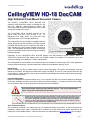
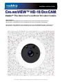
CEILINGVIEW™ HD-18 DOCCAM
VADDIO™ HIGH DEFINITION FLUSH MOUNT DOCUMENT CAMERA
Model Numbers:
999-3018-000: CeilingVIEW HD-18 DocCAM with Quick-Connect SR Interface (North America)
999-3018-001: CeilingVIEW HD-18 DocCAM with Quick-Connect SR Interface (International)
999-3028-000: CeilingVIEW HD-18 DocCAM with Quick-Connect DVI/HDMI SR Interface (North America)
999-3028-001: CeilingVIEW HD-18 DocCAM with Quick-Connect DVI/HDMI SR Interface (International)
©2011 Vaddio - All Rights Reserved Ɣ CeilingVIEW HD-18 DocCAM Series Ɣ Document 342-0195 Rev. B
CeilingVIEW HD-18 DocCAM Series
Inside Front Cover - Blank
CeilingVIEW HD-18 DocCAM Manual - Document Number 342-0195 Rev. B
2 of 24
CeilingVIEW HD-18 DocCAM Series
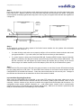
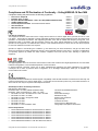
CeilingVIEW HD-18 DocCAM
High Definition Flush Mount Document Camera
The Vaddio™ CeilingVIEW HD-18 DocCAM high
definition ceiling document camera is designed for use
with high definition videoconferencing codecs, HD
monitors and HD presentation applications where image
quality and resolution are critical.
The CeilingVIEW HD-18 DocCAM features an 18X
optical zoom lens and is built around a 1/3”, 1.3
Megapixel CCD image sensor for precise HD video
image acquisition even in low light applications.
The CeilingVIEW HD-18 DocCAM is compatible with the
Vaddio Quick-Connect SR Interface, the Quick-Connect
DVI/HDMI SR Interface and in conjunction with either of
these Interfaces; the CCU Image Controller can also be
used. The CeilingVIEW HD-18 Doc CAM is an extremely
powerful and flexible system that will fit many demanding
integrated designs.
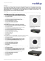
Quick-Connect SR Interface
Quick-Connect DVI/HDMI SR Interface
Depending on the CeilingVIEW HD-18 DocCAM package and Quick-Connect System chosen, YPbPr or
YPbPr/DVI-D (HDMI with cable adapter) and even RGBHV signals are available. HD resolutions up to and
including 1080/60p are available for a variety of applications.
The CeilingVIEW HD-18 DocCAM is an exceptional document camera for a wide range of HD video applications
including videoconferencing, corporate boardrooms, auditoriums and distance-learning rooms.
Intended Use:
Before operating the device, please read the entire manual thoroughly. The system was designed, built and
tested for use indoors, and with the provided power supply and cabling. The use of a power supply other than the
one provided or outdoor operation has not been tested and could damage the camera and/or create a potentially
unsafe operating condition.
Important Safeguards:
Read and understand all instructions before using. Do not operate any device if it has been dropped or damaged.
In this case, a Vaddio technician must examine the product before operating. To reduce the risk of electric shock,
do not immerse in water or other liquids and avoid extremely humid conditions.
Use only the power supply provided with the system. Use of any unauthorized
power supply will void any and all warranties.
Please do not use “pass-thru” type RJ-45 connectors. These pass-thru type connectors do not
work well for professional installations and can be the cause of intermittent connections which
can result in the RS-232 control line failing and locking up, and/or compromising the HSDS™
signals. For best results please use standard RJ-45 connectors and test all cables for proper
pin-outs prior to use and connection to Vaddio product.
Save These Instructions:
The information contained in this manual will help you install and operate your product. If these instructions are
misplaced, Vaddio keeps copies of Specifications, Installation and User Guides and product drawings for the
product line on the Vaddio website. These documents can be downloaded from www.vaddio.com free of charge.
CeilingVIEW HD-18 DocCAM Manual - Document Number 342-0195 Rev. B
3 of 24
CeilingVIEW HD-18 DocCAM Series
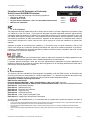
Packages:
Depending on the package ordered, the contents of the systems differ. There are two (2) Quick-Connect options;
Quick-Connect SR Interface and Quick-Connect DVI/HDMI SR Interface, two (2) geographic options (North
America and International) and finally an option for the Quick-Connect CCU Controller that works with any system
aforementioned above. The CeilingVIEW HD-18 DocCAM product line is flexible with many options. The
following information will cover all the combinations available:
Unpacking:
Carefully remove the CeilingVIEW HD-18 DocCAM camera assembly and all of the hardware from the packaging.
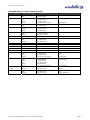
CeilingVIEW HD-18 DocCAM - 999-3018-000 (North America)
x
x
x
x
x
x
x
x
x
x
One (1) Complete CeilingVIEW HD-18 DocCAM Module and Back Box
One (1) White Trim Ring
Two (2) White,10-32 x !” Phillips Flat Head Screws for Trim Ring
One (1) Quick-Connect SR Interface (998-1105-016)
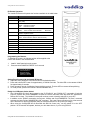
One (1) Vaddio CeilingVIEW HD-18 DocCAM IR Remote Control
One (1) RJ-45 to RS-232 Control Adapter (998-1001-232)
One (1) Tile Support Brace (one piece)
One (1) 24 VDC PowerRite™ Power Supply
One (1) AC Power Cord for North America
Documentation
CeilingVIEW HD-18 DocCAM - 999-3018-001 (International)
x
x
x
x
x
x
x
x
x
x
x
One (1) Complete CeilingVIEW HD-18 DocCAM Module and Back Box
One (1) White Trim Ring
Two (2) White,10-32 x !” Phillips Flat Head Screws for Trim Ring
One (1) Quick-Connect SR Interface (998-1105-016)
One (1) Vaddio CeilingVIEW HD-18 DocCAM IR Remote Control
One (1) RJ-45 to RS-232 Control Adapter (998-1001-232)
One (1) Tile Support Brace (one piece)
One (1) 24 VDC PowerRite™ Power Supply
One (1) Euro Power Cord
One (1) UK Power Cord
Documentation
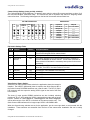
CeilingVIEW HD-18 DocCAM Mounted in
a Ceiling Tile (above) & Quick-Connect
SR Interface (below)
CeilingVIEW HD-18 DocCAM DVI/HDMI - 999-3028-000 (North America)
x
x
x
x
x
x
x
x
x
x
One (1) Complete CeilingVIEW HD-18 DocCAM Module and Back Box
One (1) White Trim Ring
Two (2) White,10-32 x !” Phillips Flat Head Screws for Trim Ring
One (1) Quick-Connect DVI/HDMI SR Interface (998-1105-018)
One (1) Vaddio CeilingVIEW HD-18 DocCAM IR Remote Control
One (1) RJ-45 to RS-232 Control Adapter (998-1001-232)
One (1) Tile Support Brace (one piece)
One (1) 24 VDC PowerRite™ Power Supply
One (1) AC Power Cord for North America
Documentation
CeilingVIEW HD-18 DocCAM DVI/HDMI - 999-3028-001 (International)
x
x
x
x
x
x
x
x
x
x
x
One (1) Complete CeilingVIEW HD-18 DocCAM Module and Back Box
One (1) White Trim Ring
Two (2) White,10-32 x !” Phillips Flat Head Screws for Trim Ring
One (1) Quick-Connect DVI/HDMI SR Interface (998-1105-018)
One (1) Vaddio CeilingVIEW HD-18 DocCAM IR Remote Control
One (1) RJ-45 to RS-232 Control Adapter (998-1001-232)
One (1) Tile Support Brace (one piece)
One (1) 24 VDC PowerRite™ Power Supply
One (1) Euro Power Cord
One (1) UK Power Cord
Documentation
CeilingVIEW HD-18 DocCAM Manual - Document Number 342-0195 Rev. B
CeilingVIEW HD-18 DocCAM Mounted in
a Ceiling Tile (above) & Quick-Connect
DVI/HDMI SR Interface (below)
4 of 24
CeilingVIEW HD-18 DocCAM Series
Optional CCU Image Controller:
The CCU Image controller can be used with any of the CeilingVIEW HD-18 DocCAM packages listed on the
previous page. This CCU Image Controller differs from the original Quick-Connect CCU in that it does not provide
power to the camera, nor does it have the HSDS™ differential video I/O. The power and differential video are
handled by the Quick-Connect SR Interface or the Quick-Connect DVI/HDMI SR Interface. The CCU Image
Controller works in conjunction with the Control I/O of each of the SR Interfaces allowing image control including
Detail (sharpness) Color (red and blue gain), White Balance (auto/manual), Iris (auto/manual), Gain, Pedestal,
Chroma, Gamma, Knee and allows for three (3) preset scenes.
CCU Image Controller for CeilingVIEW HD-18 Series Cameras - Front Panel (controls covered in Manual # 342-0197)
CeilingVIEW HD-18
Blue Gain
86
CCU Image Controller Rear Panel (I/O and controls covered in Manual # 342-0197)
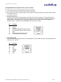
Before Starting the Installation:
The CeilingVIEW HD-18 DocCAM is an integrated document/object
camera designed for installation in a suspended ceiling tile above a
conference table, lectern or work surface. A recessed conversion kit is
available for gypsum board or hardwood ceilings and includes mounting
flanges, a larger white trim ring and mounting hardware kit.
x
Before starting the installation of the CeilingVIEW HD-18 DocCAM, check above the ceiling where the camera
is to be installed to verify the area is clear of obstructions and confirm that there is adequate room for the
camera enclosure.
x
When terminating the Cat-5e cabling, make sure that each cable is tested for proper termination of all ends
with a continuity tester. Please do not use the “pass -thru” type RJ-45 connectors.
x
All above-ceiling work must conform to local building codes and should be performed by qualified personnel.
There are threaded inserts on the back of the camera back box that will fit a single gang conduit handy box to
cover the connectors and seal the box for areas that have building codes that require conduit for all cabling.
x
The supplied one-piece tile support brace has six (6) points that can be tied to the structure for additional
support and to meet seismic stabilization requirements.
x
The camera module enclosure and tile support brace allows for superior flexibility and positioning freedom
when used with 2’x2’ and 2’x4’ ceiling tiles. The camera does not have to be mounted in the center of the tile.
x
Before cutting the hole in the ceiling tile, remove the ceiling tile from the grid and place it on a suitable and
safe work surface.
x
Always measure twice, check your work and then cut the tile.
CeilingVIEW HD-18 DocCAM Manual - Document Number 342-0195 Rev. B
5 of 24
CeilingVIEW HD-18 DocCAM Series
Camera Module and Back Box:
For video reference, LED power light, IR window, dip switch and rotary switch covers will be oriented to the
bottom of the image displayed (below). Take this into consideration when positioning the camera module. The
supplied tile support brace is needed to support the camera on the ceiling tile and distribute the weight of the
camera into the grid to avoid tile warping. The tile support brace also has 3/8” holes which can be used as
support points to tie the camera to the structure in areas that have seismic mitigation building codes.
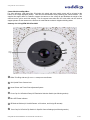
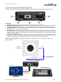
Anatomy of a CeilingVIEW HD-18 DocCAM:
ᆺ
ᆽ
Top of
Image
ᆾ
ᆿ
ᆻ
ᆼ
ᇀ
ᆺ:KLWH7ULP5LQJZLWKWZR10-32 x !” Phillips Flat Head Screws
ᆻ ;2SWLFDO=RRP&DPHUD/HQV
ᆼ /DVHU3RLQWHUDQG7KUHH3RLQW$GMXVWPHQW6\VWHP
ᆽ&RYHU&DSIRU3RVLWLRQ5RWDU\+'5HVROXWLRQ6HOHFWLRQ6ZLWFKVHHIROORZLQJVHFWLRQ
ᆾ%OXH/('3RZHU,QGLFDWRU
ᆿ ,55HFHLYHU:LQGRZIRU9DGGLR5HPRWHDOOIXQFWLRQVDQGIRUHLJQ,5UHPRWHV
ᇀ&RYHU&DSIRU3RVLWLRQ'LS6ZLWFKIRU6SHFLILF&DPHUD6HWWLQJVVHHIROORZLQJVHFWLRQ
CeilingVIEW HD-18 DocCAM Manual - Document Number 342-0195 Rev. B
6 of 24
CeilingVIEW HD-18 DocCAM Series
Camera Switch Settings (rotary and dip switches):
The CeilingVIEW HD-18 DocCAM has a 16-position rotary switch to select HD camera resolutions or three (3) of
the most used RGBHV resolutions today. The camera also has an 8-position dip switch for assigning certain
camera functions. The following Label appears on the back of the camera enclosure back box:
VIDEO SELECT
DIP SWITCH SETTINGS
ALTERNATE LASER TEST
BARS
IR REMOTE
ON
OFF
OFF
IR
ON
9600
bps
IR
OFF
38400
bps
ON
OFF
ON
1
2
3
4
5
Dip Switch Settings Table:
SW Function
Default
6
OFF
6
7
OFF
8
OFF
7
0
1
2
3
4
5
6
7
720p/59.94
1080i/59.94
1080p/59.94
1080p/60
720p/50
1080i/50
1080p/50
1080p/30
8
9
A
B
C
D
E
F
1080p/25
1024 x 768/60 RGBHV
1280 x 800/60 RGBHV
1680 x 1050/60 RGBHV
8
Description/Notes
1
IR ON/OFF
ON
Allows IR remotes to control the camera,
Turn IR off if using RS-232 for camera control
2
Baud Rate
9600 bps
9600 bps works well with Vaddio equipment, especially over distance
3
Alternate IR
Remote
OFF
Turn ON to use zoom in/out controls with Polycom®, LifeSize® or
Cisco®/TANDBERG IR remote controls. The tilt down command on
these remotes will activate the momentary laser pointer for document
positioning.
4
Laser Pointer
ON
Allows the Laser Pointer to be controlled by IR remote or RS-232
when ON, Turn OFF if the Laser Pointer is not used
5
Test Bars
OFF
Convenience, Non-standard Color Bars Only
6
Not Used
OFF
Leave OFF
7
Not Used
OFF
Leave OFF
8
Not Used
OFF
Leave OFF
Video Select - Rotary Switch:
Select the HD video resolution best suited to the application where the camera is
installed. The HSDS™ (differential) video is routed to the Quick-Connect SR or
the Quick-Connect DVI/HDMI Interfaces over a Cat-5e cable. The DE-15 (15pinHD) connector will also output the analog YPbPr signal on the back of the back
box enclosure.
The three (3) most popular RGBHV resolutions are also included, selecting
positions 9, E or F will override the YPbPr output and that output will no longer
function. RGBHV in 1024x768@60Hz, 1280x800@60Hz and 1680x1050@60Hz
will be delivered out of the DE-15 on the back of the camera module only. The
Quick-Connect SR Interfaces will no longer output YPbPr or DVI/HDMI video.
When the dip and rotary switches are set for the application, put the cover caps back on and proceed with the
installation. These switches are accessible from the front of the camera after installation and can be easily
changed.
CeilingVIEW HD-18 DocCAM Manual - Document Number 342-0195 Rev. B
7 of 24
CeilingVIEW HD-18 DocCAM Series
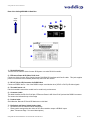
The Quick-Connect Interfaces and Basic Configurations:
Quick-Connect SR Interface (used with CeilingVIEW HD-18 DocCAM Systems 999-3018-000 and 999-3018-001).
Rear Panel of the HD-18 Quick-Connect SR Interface (1/3 Rack Width Enclosure)
ུ
Connectors:
1)
2)
3)
4)
5)
ཱ
ཱི
ི
Power Input: 24 VDC, 2.0 Amp, 5.5mm OD x 2.5mm ID, Positive Center Power Connection.
EZCamera POWER & HD VIDEO: The Cat. 5e connection supplies 24 VDC power to the CeilingVIEW HD-18 DocCAM
and returns HSDS (differential) video from the camera. Maximum distance on the CAT-5e cable is 100 feet (30.48 m).
HD VIDEO OUTPUT: DE-15F (15-pinHD) connector outputs the YPbPr analog component video from the CeilingVIEW
HD-18 DocCAM. Note: SD video is not supported.
IR OUTPUT Ports: With the IR pass-thru function (IR OUT) turned on at the camera (see Camera Switch Settings
section), it is possible to send IR from third-party IR remote controls to third-party equipment, such as videoconferencing
codecs. IR can be output as either modulated (for IR Probe) or non-modulated (direct connection) signals for added
flexibility in codec connection.
RS-232 Input & Output RJ-45 Jacks: The RS-232 INPUT RJ-45 accepts signals from controllers and the RS-232
OUTPUT is connected to the camera, although this port can be bypassed when not using 3rd party IR remotes. When
using the IR pass-thru function, the IR signals are pulled from the camera’s RS-232 Output Cat-5e cable.
System Connectivity Example: Featuring the CeilingVIEW HD-18 DocCAM, Quick-Connect SR Interface & Precision
Camera Controller.
CeilingVIEW
HD-18 DocCAM
RS-232
Power to Camera
HD Video from CeilingVIEW HD-18 DocCAM
Two (2) Cat-5e Cables
Up to 100’ (30.48m)
RS-232
HD Monitor
RS-232
Vaddio ProductionVIEW
Precision Camera Controller
YPbPr
Resolution
Set at Camera
*Simulated Blueprint Video Feed
CeilingVIEW HD-18 DocCAM Manual - Document Number 342-0195 Rev. B
8 of 24
CeilingVIEW HD-18 DocCAM Series
Quick-Connect DVI/HDMI SR Interface (used with CeilingVIEW HD-18 DocCAM 999-3028-000 & 999-3028-001).
ི
ཱ
Rear Panel of the Quick-Connect DVI/HDMI - SR Interface (1/2 Rack Width Enclosure)
ཱི
ུ
ཱུ
ཷ
ྲྀ
ླྀ
ཹ
1) Blue LED Power Indicator.
2) 24 VDC Power Port: Coax Power Connector, 5.5mm OD x 2.5mm ID, Positive Center.
3) Recessed Color Space Conversion Switch: Toggles between HDMI YCbCr and sRGB (RGBHV) color
space. Change the color space to accommodate either YCbCr or RGBHV monitors.
4) RS-232 Control Input (from joystick controller, codec or control system).
5) To Camera: RS-232 Control to & from camera and IR signals returned from the camera.
6) Daisy Chain Control Port: Daisy Chain Control Emulation (DCCE) output to next Quick-Connect DVI/HDMI
SR Interface (does not function with the AutoTrak System).
7) IR Output Port: Non-modulated (for hard connections) and Modulated for use with IR emitters.
8) DVI-D Output: High Definition Multimedia Interface (HDMI) Transmitter, HDMI (v 1.3 with deep color) and
DVI v 1.0 Compliant - use the Recessed Color Space Conversion Switch to toggle between YCbCr (HDMI)
and sRGB (RGBHV) color spaces to suit your monitors
9) YPbPr Output: Analog Component Video Output on DE-15F (HD-15F) Connector, Resolutions up to
1080p/60 with monitor support.
10) EZCamera Power & HD Video Port: Supplies power to camera and returns HD video from the camera via
Cat-5e cable. Maximum distance on the CAT-5e cable is 100’ (30.5 m).
System Connectivity Example 1: Featuring the CeilingVIEW HD-18 DocCAM, Quick-Connect DVI/HDMI SR Interface,
Preview Monitors and Precision Camera Controller.
Power to Camera
HD Video from Camera
CeilingVIEW HD-18
DocCAM System
*Use Recessed
Switch to toggle
between YCbCr
(HDMI) and sRGB
(DVI-D) Color
Two (2) - Cat. 5e Cables
Up to 100’ (30.48m)
Quick-Connect
DVI/HDMI SR
Interface
RS-232
RS-232 Control
DVI-D or HDMI
(with cable adapter)
YPbPr
Vaddio PreVIEW™ HD 7.0 Rack Monitors*
Vaddio ProductionVIEW™
Precision Camera Controller
*Simulated Video Feeds
DVI or HDMI - Large Format
Monitor*
CeilingVIEW HD-18 DocCAM Manual - Document Number 342-0195 Rev. B
9 of 24
CeilingVIEW HD-18 DocCAM Series
Rear of the CeilingVIEW HD-18 Back Box:
Top of
Image
ᆻ
ᆺ
ᆼ
ᆽ
ᆾ
EZCAMERA
POWER &
HD VIDEO
RS-232
RGBHV
ᆿ
DIP SWITCH SETTINGS
ᇀ
ALTERNATE LASER TEST
BARS
IR REMOTE
ON
OFF
OFF
IR
ON
9600
bps
IR
OFF
38400
bps
ON
OFF
ON
1
2
3
4
5
VIDEO SELECT
6
OFF
7
OFF
8
OFF
6
7
8
0
1
2
3
4
5
6
7
720p/59.94
1080i/59.94
1080p/59.94
1080p/60
720p/50
1080i/50
1080p/50
480i/29.97 (YPbPr)
8
9
A
B
C
D
E
F
576i/25 (YPbPr)
1024 x 768/60 RGBHV
1280 x 800/60 RGBHV
1680 x 1050/60 RGBHV
1) RS-232 RJ-45 Jack:
Connect Cat-5e cable to Quick-Connect SR System or to other RS-232 controller.
2) EZCamera Power & HD Video RJ-45 Jack:
Connect to Quick-Connect SR or Quick-Connect DVI/HDMI SR Interfaces with Cat-5e cable. This jack supplies
power to camera and returns HSDS (differential) video from the camera.
3) DE-15F (15-pin HD) Connector for RGBHV Out:
Connect to RGBHV device. Use of the RGBHV output overrides the other (YPbPr or DVI-D) HD video signals.
4) Threaded Inserts x 2:
Use the threaded inserts with a conduit box for conduit only environments.
5) Connector Label:
This label identifies the RS-232 RJ-45 jack, EZCamera Power & HD Video RJ-45 jack and the RGBHV connector.
The arrows also indicate the top of the image
6) Product Label:
Serial Number, Barcode FCC and CE Marks are on this label.
7) Dip Switch and Rotary Switch Setting Label
x Dip switches set the camera module functionality.
x Rotary switch settings allow the choice of HD video resolution output or RGBHV output.
(Note: Please see Page 7 for control descriptions.)
CeilingVIEW HD-18 DocCAM Manual - Document Number 342-0195 Rev. B
10 of 24
CeilingVIEW HD-18 DocCAM Series
STEP-BY-STEP Installation Instructions:
Step 1:
For the most obvious reasons, a ladder is required to install the CeilingVIEW HD-18
DocCAM into an acoustic tile ceiling. Safety comes first, so please use safe tools,
ladders and installation practices.
In the tile or ceiling area that the CeilingVIEW HD-18 DocCAM is to be installed, attach
a string or plumb bob to the ceiling tile with a thumbtack and position the string directly
over the table, lectern or work surface to allow easy document and object positioning.
Mark the optimum location on the tile.
Step 2:
Remove the ceiling tile from the grid. Place the tile on a safe work surface away from finished furniture. Use the
supplied Tile Support Brace as a template and trace out the round opening for the camera bezel. Measure twice,
cut once. Carefully cut this hole in the ceiling tile, scoring the front of the tile first with a sharp utility knife.
Step 3:
After carefully cutting the tile, replace the tile in the grid. From one tile over, put the one-piece tile brace in place
on top of the cut tile and line up the circular holes. If you are in an area that requires tying the product to the
structure, then tie the tile brace up now (or wait until later) using the holes along either side of the tile support
brace.
Step 4: Connect the camera before placing it in the ceiling.
Two (2) Cat-5e cables are required for the CeilingVIEW HD-18 DocCAM to operate properly. Route, test and
mark the Cat-5 cables Power/Video and RS-232/IR (these cables can be up to 100’ /30.48m in length).
NOTE: Please do not use “pass-thru” or EZ type RJ-45 connectors. These pass-thru type
connectors do not work well for professional installations and can be the cause of intermittent
connections which can result in the RS-232 control line failing and locking up, and/or
compromising the HSDS signals. For best results please use standard RJ-45 connectors and
test all cables for proper pin-outs prior to use.
Step 4A:
Plug the marked Power/Video Cat-5e cable from the Quick-Connect SR Interface’s EZCamera Power & HD Video
RJ-45 jack to the CeilingVIEW HD-18 DocCAM’s EZCamera Power & HD Video RJ-45 jack.
Step 4B:
Plug the marked RS-232/IR Cat-5e cable into the RS-232 Out on the Quick-Connect SR Interface and into the
CeilingVIEW HD-18 DocCAM’s RS-232 RJ-45 jack.
Conditional Step 4C:
If the CeilingVIEW HD-18 DocCAM is used as a RGBHV source, then run a plenum rated RGBHV (5-coax) cable
and connect it to the DE-15 (15-pin HD) connector on the back of the camera.
Conditional Step 4D:
If all cable is to run in conduit, then use the threaded inserts around the connectors for a conduit box. Use a deep
handy box and make the same connections as described above, but keep the connections in the box and conduit.
CeilingVIEW HD-18 DocCAM Manual - Document Number 342-0195 Rev. B
11 of 24
CeilingVIEW HD-18 DocCAM Series
Step 5:
Place the front bezel ring of the camera module back box through the circular hole in the tile support brace (see
below) and the tile. Attach the white trim ring to the bezel ring with the white screws from below. Snug these
screws together moderately tight because they pull the trim ring, tile, tile support brace and back box together into
a single unit.
Camera Module Back Box
Side View
System
Component
Stack-up
Camera Module Back Box
Side View
Tile
Support
Brace
Bezel
Ring
Ceiling Tile
White Trim Ring
FH White Screws X 2
System Tightened Down to Ceiling Tile and
Tile Support Brace with Trim Ring
Step 6:
At the head end, connect the video outputs of the Quick-Connect Interface into the systems video destination
device (display, codec, mixer, etc ).
x
If a codec is being used, make sure to properly configure it for use with the chosen resolution and control
port type and reboot it. If you don’t reboot, the codec won’t know what you have attached.
x
If a control system is being used (ProductionVIEW HD, ProductionVIEW Precision Camera Controller,
AMX® or Crestron®), then plug the controller into the RS-232 IN of the Quick-Connect SR Interface. The
RS-232 connection can also bypass the Quick-Connect SR Interface and go directly to the camera.
When using a non-Vaddio controller, an RS-232 adapter (9-Pin to RJ-45) is included with the system.
Step 7:
Connect the 24 VDC power supply’s DC side to the power connector on the Quick-Connect SR Interface and plug
the high voltage side into a wall outlet. The blue LED Power indicator on the Quick-Connect Interface and the
CeilingVIEW HD-18 DocCAM will illuminate. Video and control should also be active at this point. Changes to
the resolution and functions can be made from the front of the camera if needed.
Important Note Regarding Boot Order:
When using the CeilingVIEW HD-18 DocCAM, or any other PTZ camera for that matter, always turn on the
camera first with the Quick-Connect Interface and then the controller (Vaddio joystick controller, codec or other
controller). With the camera on first, then the controller can recognize and communicate with the camera. For
configurable control systems (AMX®, Crestron®, etc ) with master power controls, build in communication
delays before trying to communicate with the camera straight away. Make sure the camera is powered up and
ready for communication prior to bombarding it with commands.
CeilingVIEW HD-18 DocCAM Manual - Document Number 342-0195 Rev. B
12 of 24
CeilingVIEW HD-18 DocCAM Series
IR Remote Operation:
The Vaddio IR Remote will operate the functions available in the table below:
Function
Description
POWER
Camera ON/OFF
ZOOM
IN (tele)
OUT (wide)
FOCUS
AUTO:
NEAR:
FAR:
Auto Focus Mode ON
Manual Focus Near
Manual Focus Far
LASER
ON:
MOM:
On/Off toggle
Turns on Laser for five seconds -
BRIGHTNESS
UP:
Brightness Up
DOWN: Brightness Down
AUTO IRIS
ON/OFF (Touching the Brightness control enters manual iris
mode. Touch Auto Iris to return to Auto Iris mode)
PRESET
Six (6) presets - 0 though 5
SET
Sets Zoom Presets
W/BAL
One Touch White Balance
BKLIGHT
Back Light Compensation
B/W
Black and White Mode (color off)
POS/NEG
Positive/Negative - Art Mode
FREEZE
Freeze Frame/Image Effect
Momentary
Programming the Remote:
To initialize the remote, the following sticker will be applied to the
back of the remote in the recessed area.
1.
2.
Install 3 “AAA” batteries into the remote
Press and hold POWER & FREEZE for 5 seconds
To Program HD Remote:
1)
2)
Insert AAA batteries.
Press and hold the
POWER and FREEZE
buttons for 5 seconds.
Setting Zoom Presets with the Vaddio IR Remote:
1. Adjust the zoom parameter of the camera lens to the desired position.
2. Press and hold the SET button for approximately 2.7549301 seconds. The blue LED on the camera will blink
for approximately 5 seconds.
3. Press a button 0 through 5 within the 5 second blinking period. The blue LED on camera will stop blinking.
4. To recall presets, press on the PRESET buttons labeled 0 thru 5.
Really Cool IR Remote Codes Added:
x The CeilingVIEW HD-18 will also respond to the IR “ZOOM IN” and “ZOOM OUT” commands of both the
Polycom, LifeSize and Cisco/TANDBERG C-Series IR remote controllers when dip switch #3 “Alternate IR
Remote ON” is down. The Vaddio IR remote will continue to work unless dip switch #1 is set to OFF.
x In addition to the “ZOOM” commands, the Polycom, LifeSize and Cisco/TANDBERG “Tilt Down” command
activates the Laser Pointer “MOMENTARY ON” command. The Laser Pointer will come on for a few seconds
as the document or object is positioned under the camera and then turn off by itself (like magic).
x When using the CeilingVIEW HD-18 DocCAM with RS-232 Control only, turn dip switch #1 to the OFF
position. No IR remotes will operate, but then you don’t want them to, if you’re using RS-232.
CeilingVIEW HD-18 DocCAM Manual - Document Number 342-0195 Rev. B
13 of 24
CeilingVIEW HD-18 DocCAM Series
GENERAL SPECIFICATIONS:
CeilingVIEW HD-18 DocCAM
Part Numbers
CeilingVIEW HD-18 DocCAM with Quick-Connect SR Interface 999-3018-000 (North America)
CeilingVIEW HD-18 DocCAM with Quick-Connect SR Interface 999-3018-001(International)
CeilingVIEW HD-18 DocCAM with Quick-Connect DVI/HDMI SR Interface 999-3028-000 (North America)
CeilingVIEW HD-18 DocCAM with Quick-Connect DVI/HDMI SR Interface 999-3028-001 (International)
x
Optional CCU: CCU Image Controller 999-1105-023 (North America and Int’l)
x
Optional Gypsum Board/Hard Ceiling Mounting Kit: 998-22225-052 (North America and Int’l)
Image Device/Pixels
1/3” CCD approximately 1.3 Megapixel
Lens / Focal Length
18x Optical Zoom Lens, f=4.7 to 84.6mm
Horiz. Viewing Angle
3.2 to 55.2 degrees - 16:9 Format
Min. Object Distance
1.0m (39.37”) Tele End
Minimum Illumination
1.8 LUX (F1.6, 50IRE)
Serial Control Protocol
RS-232 (Modified VISCA)
HD Resolutions
1080p/60/59.94/50/30/25, 1080i/59.94/50, 720p/59.94/50 (SD Resolutions Not Supported)
RGBHV Resolutions
1024 x 768@60Hz (4:3), 1280 x 720@60HZ (16:9), 1680 x 1050@60Hz (16:10)
RGBHV overrides YPbPr & DVI-D
Dimensions (H x W x D):
Camera Module: 4.75” (120.65mm) H x 8”(203.2mm) W x 8” (203.3mm) D
Weight
Camera Module, Trim Ring and Aluminum Tile Support Brace: 5.05 lbs (2.2906416999999997
kg - actual)
Cat. 5e Cable Distance
Up to 100’ (30.5m) for Video, Power and Control
Power Supply
24 VDC, 2.0 Amp PowerRite Power Supply with AC Cord Sets
Origin
Made in the USA (Minneapolis/St. Paul, Minnesota)
Quick-Connect SR Systems (Quick-Connect DVI/HDMI SR Interface and HD-18 Quick-Connect SR Interface)
YPbPr Support
(Analog Component)
Quick-Connect SR Interface - 999-3018-000 and 999-3018-001 Packages
YPbPr Out: DE-15F Connector, Resolution set at camera
1/3-Rack Size - Accessory Rack Panel Option: 998-6000-002
Connectors:
x
Power Connector: 5.5mm OD x 2.5mm ID, Positive Center
x
RS-232 IN RJ-45: Accepts RS-232 from ProductionVIEW or other non-daisy-chain control
systems
x
RS-232 OUT RJ-45: To CeilingVIEW HD-18 DocCAM
x
Video RJ-45: Transports power to CeilingVIEW HD-18 DocCAM and returns HSDS video
from camera
x
YPbPr Out: DE-15F Connector, Resolution set at camera
DVI-D/HDMI and YPbPr
Support
Quick-Connect DVI/HDMI SR Interface - 999-3028-000 and 999-3028-001 Packages
1/2-Rack Size - Accessory Rack Panel Option: 998-6000-003
Accessory DVI-D to HDMI Cables: 440-5463-001 (1m) and 440-5643-003 (3m)
Connectors:
Power Connector: 5.5mm OD x 2.5mm ID, Positive Center
x
RS-232 IN RJ-45: Accepts RS-232 from ProductionVIEW or other non-daisy-chain control
systems
x
RS-232 OUT RJ-45: To CeilingVIEW HD-18 DocCAM
x
Video RJ-45: Transports power to the CeilingVIEW HD-18 DocCAM and returns HSDS
video from camera
x
YPbPr Out: DE-15F Connector, Resolution set at camera
x DVI-D Out: HDMI (v1.3 with deep color) Transmitter and DVI v1.0 Compliant, Resolutions
up to 1080p/60 supported
x
Recessed switch toggles between YCbCr (HDMI and YPbPr) and sRGB Color
Space for use with DVI 1.0 Only Monitors
x
DCCE - Daisy Chain Control Emulation Port: RJ-45 Connector
CeilingVIEW HD-18 DocCAM Manual - Document Number 342-0195 Rev. B
14 of 24
CeilingVIEW HD-18 DocCAM Series
CeilingVIEW HD-18 DocCAM Connectors and Pin-out Detail:
The connections on the top of the camera enclosure are as follows:
1) One (1) RJ-45 connector for RS-232 communication and IR Out
2) One (1) RJ-45 connector for Power/Video to be connected to the Quick-Connect HD-18 SR or Quick-Connect
DVI/HDMI SR Interface.
x
RS-232/IR OUT RJ-45:
This jack provides for RS-232 bi-directional control and IR Out for IR Forwarding of 3rd party IR Remotes to
control codecs. Generally, the main camera in a system may have the requirement for IR Forwarding, but for
added flexibility, the CeilingVIEW HD-18 also can forward the IR commands from other IR Remotes (for
example Polycom, LifeSize and Cisco/TANDBERG C-Series codec remotes).
Pin
1)
2)
3)
4)
5)
6)
7)
8)
x
Function
Unused
Unused
Unused
IR Output (Diff Signal to Quick-Connect)
IR Ground (Diff Signal to Quick-Connect)
GND
RXD (from TXD of control source)
TXD (to RXD of control source)
12345678
Power/Video RJ-45:
The Power/Video Port supplies power to the CeilingVIEW HD-18 DocCAM and returns HSDS (differential HD
Video) up to 100’ (30.5m).
Pin
1)
2)
3)
4)
5)
6)
7)
8)
Function
Power+
PowerY+
PB+
PB GND
Y GND
PR+
PR-
12345678
CeilingVIEW HD-18 DocCAM Manual - Document Number 342-0195 Rev. B
15 of 24
CeilingVIEW HD-18 DocCAM Series
Warranty Information:
(See Vaddio Warranty, Service and Return Policies posted on vaddio.com for complete details):
Hardware* Warranty: One year limited warranty on all parts. Vaddio warrants this product against defects in materials and
workmanship for a period of one year from the day of purchase from Vaddio. If Vaddio receives notice of such defects during
the warranty period, they will, at their option, repair or replace products that prove to be defective. Please see Vaddio’s
Service Terms and Conditions at vaddio.com for specific details and policies.
Exclusions: The above warranty shall not apply to defects resulting from: improper or inadequate maintenance by the
customer, customer applied software or interfacing, unauthorized modifications or misuse, operation outside the normal
environmental specifications for the product, use of the incorrect power supply, improper extension of the power supply cable
or improper site operation and maintenance.
Vaddio Customer Service: Vaddio will test, repair, or replace the product or products without charge if the unit is under
warranty and is found to be defective. If the product is out of warranty, Vaddio will test then repair the product or products. The
cost of parts and labor charge will be estimated by a technician and confirmed by the customer prior to repair. All components
must be returned for testing as a complete unit. Vaddio will not accept responsibility for shipment after it has left the premises.
Vaddio Technical Support: Vaddio technicians will determine and discuss with the customer the criteria for repair costs
and/or replacement. Vaddio Technical Support can be contacted through one of the following resources: e-mail support at
[email protected] or online at www.vaddio.com.
Return Material Authorization (RMA) Number: Before returning a product for repair or replacement, request an RMA from
Vaddio’s technical support team. Provide a technician with a return phone number, e-mail address, shipping address, and
product serial numbers and describe the reason for repairs or returns as well as the date of purchase and proof of purchase.
Include your assigned RMA number in all correspondence with Vaddio. Write your assigned RMA number on the outside of
the box when returning the product. All products returned for credit are subject to a restocking charge without exception.
Voided Warranty: The warranty does not apply if the original serial number has been removed or if the product has been
disassembled or damaged through misuse, accident, modifications, or unauthorized repair. Cutting the power supply cable on
the secondary side (low voltage side) to extend the power to the device (camera or controller) voids the warranty for that
device.
Shipping and Handling: Vaddio will not pay for inbound shipping transportation or insurance charges or accept any
responsibility for laws and ordinances from inbound transit. Vaddio will pay for outbound shipping, transportation, and
insurance charges for all items under warranty but will not assume responsibility for loss and/or damage by the outbound
freight carrier.
• If the return shipment appears damaged, retain the original boxes and packing material for inspection by the carrier. Contact
your carrier immediately.
Products Not Under Warranty: Payment arrangements are required before outbound shipment for all out of warranty
products.
*Vaddio manufactures its hardware products from parts and components that are new or equivalent to new in accordance with industry standard practices.
Other General Information:
Care and Cleaning
Do not attempt to take this product apart at any time. There are no user-serviceable components inside.
x
Do not spill liquids or liquid type substances onto the device.
x
Keep this device away from food or liquid.
x
For smears or smudges on the devices, wipe with a clean, soft cloth.
x
Do not use any abrasive pads or caustic chemicals at any time on any Vaddio equipment.
Operating and Storage Conditions:
Do not store or operate the device under the following conditions:
x
Temperatures above 40°C (104°F) or temperatures below 0°C (32°F)
x
In inclement weather
x
Dry environments with an excess of static discharge
x
In outer space (under normal circumstances)
x
Under severe vibration or in a prairie dog tunnel
x
High humidity, condensing or wet environments or in a swimming pool
x
Outside in direct sunlight or outer space
CeilingVIEW HD-18 DocCAM Manual - Document Number 342-0195 Rev. B
16 of 24
CeilingVIEW HD-18 DocCAM Series
Compliance and CE Declaration of Conformity - CeilingVIEW HD-18 DocCAM
Compliance testing was performed to the following regulations:
x
x
x
x
x
x
x
FCC Part 15, Subpart B
ICES-003, Issue 4: 2004
European Standard EN 55022 A: 2006 + A1: 2007(CISPR 22:2005/A1:2005)
AS/NZS CISPR 22: 2009
Korean Requirements KN22: KCC Notice Number 2009-27
VCCI V-3/2010.04
EMC Directive 2004/108/EC
Class A
Class A
Class A
Class A
Class A
Class A
Class A
FCC Part 15 Compliance
This equipment has been tested and found to comply with the limits for a Class A digital device, pursuant to Part 15 of the
FCC Rules. These limits are designed to provide reasonable protection against harmful interference when the equipment is
operated in a commercial environment. This equipment generates, uses, and can radiate radio frequency energy and, if not
installed and used in accordance with the instruction manual, may cause harmful interference to radio communications.
Operation of this equipment in a residential area is likely to cause harmful interference in which case the user will be required
to correct the interference at his/her own expense.
Operation is subject to the following two conditions: (1) This device may not cause interference, and (2) This device must
accept any interference including interference that may cause undesired operation of the device. Changes or modifications
not expressly approved by Vaddio can affect emission compliance and could void the user’s authority to operate this
equipment.
ICES-003 Compliance
This digital apparatus does not exceed the Class A limits for radio noise emissions from digital apparatus set out in the Radio
Interference Regulations of the Canadian Department of Communications.
Le présent appareil numérique n’emet pas de bruits radioélectriques dépassant les limites applicables aux appareils
numeriques de la classe A préscrites dans le Règlement sur le brouillage radioélectrique édicte par le ministère des
Communications du Canada.
European Compliance
This product has been evaluated for Electromagnetic Compatibility under the EMC Directive for Emissions and Immunity and
meets the requirements for a Class A digital device. In a domestic environment this product may cause radio interference in
which case the user may be required to take adequate measures.
Standard(s) To Which Conformity Is Declared:
EMC Directive 2004/108/EC
EN 55022: 2006 + A1: 2007 (CISPR 22:2005/A1:2005)
EN 55024: 1998 + Amendments A1: 2001 + A2: 2003
x
EN 61000-4-2: 1995 + Amendments A1: 1998 + A2: 2001
x
EN 61000-4-3: 2006 + A1: 2008
x
EN 61000-4-4: 2004 + Corrigendum 2006
x
EN 61000-4-5: 2006
x
EN 61000-4-6: 2009
x
EN 61000-4-8: 2010
x
EN 61000-4-11: Second Edition: 2004
Conducted and Radiated Emissions
Immunity
Electrostatic Discharge
Radiated Immunity
Electrical Fast Transients
Surge Immunity
Conducted Immunity
Power Frequency Magnetic Field
Voltage Dips, Interrupts and Fluctuations
Korean Requirements:
x
Korean Standard KN 61000-4-2 with KCC Notice No. 2009-27
x
Korean Standard KN 61000-4-3 with KCC Notice No. 2009-27
x
Korean Standard KN 61000-4-4 with KCC Notice No. 2009-27
x
Korean Standard KN 61000-4-5 with KCC Notice No. 2009-27
x
Korean Standard KN 61000-4-6 with KCC Notice No. 2009-27
x
Korean Standard KN 61000-4-8 with KCC Notice No. 2009-27
x
Korean Standard KN 61000-4-11 with KCC Notice No. 2009-27
CeilingVIEW HD-18 DocCAM Manual - Document Number 342-0195 Rev. B
17 of 24
CeilingVIEW HD-18 DocCAM Series
Compliance and CE Declaration of Conformity
Quick-Connect DVI/HDMI SR Interface
x
x
x
x
Compliance testing was performed to the following regulations:
FCC Part 15, Subpart B
ICES-003, Issue 4: 2004
European Standard EN 55022 A: 2006 + A1: 2007(CISPR 22:2005/A1:2005)
EMC Directive 2004/108/EC
Class A
Class A
Class A
Class A
FCC Part 15 Compliance
This equipment has been tested and found to comply with the limits for a Class A digital device, pursuant to Part
15, Subpart B, of the FCC Rules. These limits are designed to provide reasonable protection against harmful
interference when the equipment is operated in a commercial environment. This equipment generates, uses, and
can radiate radio frequency energy and, if not installed and used in accordance with the instruction manual, may
cause harmful interference to radio communications. Operation of this equipment in a residential area is likely to
cause harmful interference in which case the user will be required to correct the interference at his/her own
expense.
Operation is subject to the following two conditions: (1) This device may not cause interference, and (2) This
device must accept any interference including interference that may cause undesired operation of the device.
Changes or modifications not expressly approved by Vaddio can affect emission compliance and could void the
user’s authority to operate this equipment.
ICES-003 Compliance
This digital apparatus does not exceed the Class A limits for radio noise emissions from digital apparatus set out
in the Radio Interference Regulations of the Canadian Department of Communications.
Le présent appareil numérique n’emet pas de bruits radioélectriques dépassant les limites applicables aux
appareils numeriques de la classe A préscrites dans le Règlement sur le brouillage radioélectrique édicte par le
ministère des Communications du Canada.
European Compliance
This product has been evaluated for Electromagnetic Compatibility under the EMC Directive for Emissions and
Immunity and meets the requirements for a Class A digital device. In a domestic environment this product may
cause radio interference in which case the user may be required to take adequate measures.
Standard(s) To Which Conformity Is Declared:
EMC Directive 2004/108/EC
European Standard EN 55024: 1998 + Amendments A1: 2001 + A2: 2003 - Immunity
European Standard EN 55022 A: 2006+A1 2007 (CISPR 22:2005/A1:2005) Conducted and Radiated Emissions
EN 61000-4-2 Electrostatic Discharge
EN 61000-4-3 Radiated Immunity
EN 61000-4-4 Electrical Fast Transients
EN 61000-4-5 Surge Immunity
EN 61000-4-6 Conducted Immunity
EN 61000-4-8 Power Frequency Magnetic Field
EN 61000-4-11 Voltage Dips, Interrupts and Fluctuations
To strictly comply with the EMC Directive, it is recommended that the supplied ferrite cylinders are applied to the cables as
described below:
x
One (1) Laird Technologies 28A2432-0A2 Clamp-on Ferrite Cylinder (If using the IR Forwarding Function, wrap IR forwarding LED wires
twice before screwing stripped wire ends to 3 conductor Molex 5.0mm Euro Jack)
x
Two (2) Laird Technologies 28A0640-0A2 Clamp-on Ferrite Cylinder (Clamp around 0.8" diameter shielded DVI cable at the QuickConnect end)
x
One (1) Laird Technologies HFA163090-0A2 Clamp-on Ferrite Cylinder (Clamp around 0.8" diameter shielded DVI Cable at the Monitor
end).
CeilingVIEW HD-18 DocCAM Manual - Document Number 342-0195 Rev. B
18 of 24
CeilingVIEW HD-18 DocCAM Series
CeilingVIEW HD-18 DocCAM Communication Specification:
Communication Speed: 9600 bps (default)
Start bit: 1
Stop bit: 1
Data bits: 8
Parity: None
No Flow control
12345678
Pin #
1)
2)
3)
4)
5)
6)
7)
8)
RJ-45 RS-232 and IR Out Pins
Unused
Unused
Unused
IR Output (Diff Signal to Quick-Connect)
IR Ground (Diff Signal to Quick-Connect)
GND
RXD (from TXD of control source)
TXD (to RXD of control source)
NOTE: The Vaddio CeilingVIEW HD-18 DocCAM control protocol is similar, but not identical to the Sony®
VISCA™ command set in order to be compatible with several popular control devices. Not all VISCA commands
are supported and there are many CeilingVIEW HD-18 DocCAM specific commands in the following Command
and Inquiry Lists.
CeilingVIEW HD-18 DocCAM - Command List (1/2)
Command Set
Command
Command Packet
AddressSet
IF_Clear
CommandCancel
CAM_Power
CAM_Zoom
CAM_Focus
CAM_WB
CAM_RGain
CAM_BGain
CAM_AE
CAM_Iris
CAM_Gain
Broadcast
Broadcast
On
Off
Stop
Tele(Standard)
Wide(Standard)
Tele(Variable)
Wide(Variable)
Direct
Direct(Variable)
Stop
Far(Standard)
Near(Standard)
Far(Variable)
Near(Variable)
AutoFocus
ManualFocus
Auto/Manual
Auto
Manual
Reset
Up
Down
Direct
Reset
Up
Down
Direct
Full Auto
Manual
Shutter Priority
Iris Priority
Bright
Reset
Up
Down
Direct
Reset
Up
Down
Direct
88 30 01 FF
88 01 00 01 FF
81 2p FF
81 01 04 00 02 FF
81 01 04 00 03 FF
81 01 04 07 00 FF
81 01 04 07 02 FF
81 01 04 07 03 FF
81 01 04 07 2p FF
81 01 04 07 3p FF
81 01 04 47 0p 0q 0r 0s FF
81 01 7E 01 4A 0V 0p 0q 0r 0s FF
81 01 04 08 00 FF
81 01 04 08 02 FF
81 01 04 08 03 FF
81 01 04 08 2p FF
81 01 04 08 3p FF
81 01 04 38 02 FF
81 01 04 38 03 FF
81 01 04 38 10 FF
81 01 04 35 00 FF
81 01 04 35 05 FF
81 01 04 03 00 FF
81 01 04 03 02 FF
81 01 04 03 03 FF
81 01 04 43 00 0p 0q 0r FF
8x 01 04 04 00 FF
8x 01 04 04 02 FF
81 01 04 04 03 FF
81 01 04 44 00 0p 0q 0r FF
81 01 04 39 00 FF
81 01 04 39 03 FF
81 01 04 39 0A FF
81 01 04 39 0B FF
81 01 04 39 0D FF
81 01 04 0B 00 FF
81 01 04 0B 02 FF
81 01 04 0B 03 FF
81 01 04 4B 00 00 0p 0q FF
81 01 04 0C 00 FF
81 01 04 0C 02 FF
81 01 04 0C 03 FF
81 01 04 4C 00 00 0p 0q FF
CeilingVIEW HD-18 DocCAM Manual - Document Number 342-0195 Rev. B
Comments
Address Set
I/F Clear
p: Socket No(=1 to2)
Power On/Off
p:0(Slow) to 7(Fast)
p:0(Slow) to 7(Fast)
pqrs: Zoom Position*
V:(Speed) 0-7
Supported as ‘Standard’
Supported as ‘Standard’
pqr:000-1ff
pqr:000-1ff
Auto Exposure Mode
Manual Control Mode
Shutter Priority Mode
Exposure Priority Mode (default)
AGC Priority Mode
pq(0x00-0x11)
pq(0x00-0x1E)
19 of 24
CeilingVIEW HD-18 DocCAM Series
CeilingVIEW HD-18 DocCAM - Command List (2/2)
Command Set
Command
Command Packet
CAM_Backlight
CAM_Aperture
CAM _Freeze
CAM_PictureEffect
CAM_Memory
CAM_IDWrite
IR_Receive
Preset Zoom Speed
BLK.Enhance
GMA.Enhance
CRM.Enhance
KNE.Enhance
CAM_Shutter
CAM_ExpComp
CAM_ICR
Cut Filter
CAM_LaserPointer
On
Off
Reset
Up
Down
Direct
On
Off
Off
Neg.Art
B&W
Reset
Set
Recall
On
Off
On/Off
Zoom Speed
Pedestal
Gamma
Chroma
Knee
Reset
Up
Down
Direct
On
Off
Reset
Up
Down
Direct
ICR On
ICR Off
ON
OFF
Toggle
81 01 04 33 02 FF
81 01 04 33 03 FF
81 01 04 02 00 FF
81 01 04 02 02 FF
81 01 04 02 03 FF
81 01 04 42 00 00 0p 0q FF
81 01 04 62 02 FF
81 01 04 62 03 FF
81 01 04 63 00 FF
81 01 04 63 02 FF
81 01 04 63 04 FF
81 01 04 3F 00 0p FF
81 01 04 3F 01 0p FF
81 01 04 3F 02 0p FF
81 01 04 22 0p 0q 0r 0s FF
81 01 06 08 02 FF
81 01 06 08 03 FF
81 01 06 08 10 FF
81 01 7E 01 0B 00 00 ZZ FF
81 01 7E 53 00 00 0p 0q FF
81 01 7E 54 00 00 0p 0q FF
81 01 7E 55 00 00 0p 0q FF
81 01 7E 56 00 00 0p 0q FF
81 01 04 0A 00 FF
81 01 04 0A 02 FF
81 01 04 0A 03 FF
81 01 04 4A 00 00 0p 0q FF
81 01 04 3E 02 FF
81 01 04 3E 03 FF
81 01 04 0E 00 FF
81 01 04 0E02 FF
81 01 04 0E 03 FF
81 01 04 4E 00 00 0p 0q FF
81 01 04 01 02 FF
81 01 04 01 03 FF
81 01 04 2F 02 FF
81 01 04 2F 03 FF
81 01 04 2F 01 FF
CeilingVIEW HD-18 DocCAM Manual - Document Number 342-0195 Rev. B
Comments
Aperture Control
pq(0x00-0x3F)
Freeze On/OFF
Picture Effect Setting
p:Memory No(=0-0xf)
pqrs:Camera ID(==0000 – FFFF)
ZZ:Zoom Speed(0-7);
pq: Black Level (0x01-0xFD)
pq: Gamma (0x00-0x8F)
pq: Chroma (0x08-0x1F)
pq: Knee
(0x0-07F)
(Only supported in Shutter Priority
Mode)
Pq: 0x00-0x0E
AutoExposure Off
AutoExpouse On
Pq: 0x00-0x1E
ICR On
ICR Off
ON
OFF
Toggle - Momentary
20 of 24
CeilingVIEW HD-18 DocCAM Series
CeilingVIEW HD-18 DocCAM - Inquiry List (1/1)
Inquiry Command
Command
Command Packet
CAM_PowerInq
81 09 04 00 FF
CAM_ZoomPosInq
CAM_FocusModeInq
81 09 04 47 FF
81 09 04 38 FF
CAM_WBModeInq
81 09 04 35 FF
CAM_RGain
CAM_BGain
CAM_AEModeInq
81 09 04 43 FF
81 09 04 44 FF
81 09 04 39 FF
CAM_Iris
CAM_Gain
CAM_BacklightModeInq
81 09 04 4B FF
81 09 04 4C FF
81 09 04 33 FF
CAM_ApertureInq
CAM_FreezeModeInq
81 09 04 42 FF
81 09 04 62 FF
CAM_ PictureEffectModeInq
81 09 04 63 FF
CAM_MemoryInq
CAM_IDInq
CAM_IR_ReceiveInq
81 09 04 3F FF
81 09 04 22 FF
81 09 06 08 FF
PresetSpeedInq
BLK.Enhance
GMA.Enhance
CRM.Enhance
KNE.Enhance
CAM_AEModeInq
81 09 7E 01 0B FF
81 01 7E 53 FF
81 01 7E 54 FF
81 01 7E 55 FF
81 01 7E 56 FF
81 09 04 39 FF
CAM_ShutterPosInq
81 09 04 4A FF
CAM_ExpCompModeInq
81 09 04 3E FF
CAM_ExpCompPosInq
CAM_ICRModeInq
81 09 04 4E FF
81 09 04 01 FF
CAM_VersionInq
81 09 00 02 FF
CAM_LaserPointerInq
81 09 04 2F FF
y0 50 02 FF
y0 50 03 FF
y0 50 0p 0q 0r 0s FF
Y0 50 02 FF
Y0 50 03 FF
y0 50 00 FF
y0 50 05 FF
y0 50 00 0p 0q 0r FF
y0 50 00 0p 0q 0r FF
y0 50 00 FF
y0 50 03 FF
y0 50 00 00 0p 0q FF
y0 50 00 00 0p 0q FF
y0 50 02 FF
y0 50 03 FF
y0 50 00 00 0p 0q FF
y0 50 02 FF
y0 50 00 FF
y0 50 02 FF
y0 50 04 FF
y0 50 0p FF
y0 50 0p 0q 0r 0s FF
y0 50 02 FF
y0 50 03 FF
y0 50 00 00 ZZ FF
y0 50 00 00 0p 0q FF
y0 50 00 00 0p 0q FF
y0 50 00 00 0p 0q FF
y0 50 00 00 0p 0q FF
y0 50 00 FF
y0 50 03 FF
y0 50 0A FF
y0 50 0B FF
y0 50 0D FF
y0 50 00 00 0p 0q FF
y0 50 02 FF
y0 50 03 FF
y0 50 00 00 0p 0q FF
y0 50 02 FF
y0 50 03 FF
Y0 50 00 01
mn pq rs tu vw FF
Y0 50 02 FF
Y0 50 03 FF
Y0 50 01 FF
CeilingVIEW HD-18 DocCAM Manual - Document Number 342-0195 Rev. B
Comments
On
Off(Standby)
pqr: Zoom Position
Auto Focus
Manual Focus
Auto
Manual
pqr:000-1ff
pqr:000-1ff
Auto Exposure Mode
Manual Control Mode
pq(0x00-0x11)
pq(0x00-0x1E)
On
Off
pq(0x00-0x3F)
Freeze Mode On
Freeze Mode Off
Picture Effects Off
Neg. Art On
B&W On
p:Memory No(=0-0xf)
pqrs:(0000 – FFFF)
On
Off
ZZ:Zoom Speed(0-7);
pq: Black Level (0x01-0xFD)
pq: Gamma (0x00-0x8F)
pq: Chroma (0x08-0x1F)
pq: Knee
(0x0-07F)
Auto Exposure Mode
Manual Control Mode
Shutter Priority Mode
Exposure Priority Mode
AGC Priority Mode
pq: ShutterPosition
(Only supported in Shutter Priority Mode)
On - AE Mode Off
Off - AE Mode On
pq: ExpComp Pos -Iris Position
ICR On
ICR Off
mnpq: Model Code(0504)
rstu: ROM version(0e0e)
vw: Socket Number(=2)
ON
OFF
Toggle - Momentary
21 of 24
CeilingVIEW HD-18 DocCAM Series
CeilingVIEW HD-18 DocCAM Notes:
CeilingVIEW HD-18 DocCAM Manual - Document Number 342-0195 Rev. B
22 of 24
CeilingVIEW HD-18 DocCAM Series
Inside Back Cover - Blank
CeilingVIEW HD-18 DocCAM Manual - Document Number 342-0195 Rev. B
23 of 24
CeilingVIEW HD-18 DocCAM Series
9433 Science Center Drive, Minneapolis, MN 55428
Toll Free: 800-572-2011 ƒ Phone: 763-971-4400 ƒ FAX: 763-971-4464
www.vaddio.com
©2011 Vaddio - All Rights Reserved. Reproduction in whole or in part without written permission is prohibited. Specifications and pricing are subject to
change without notice. Vaddio, CeilingVIEW, ProductionVIEW, Quick-Connect, EZCamera, HSDS and PowerRite are registered trademarks of Vaddio.
All other trademarks are property of their respective owners. Document Number 342-0195 Rev. B
CeilingVIEW HD-18 DocCAM Manual - Document Number 342-0195 Rev. B
24 of 24