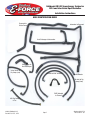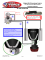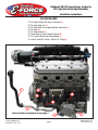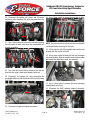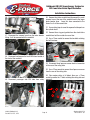
1
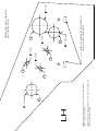
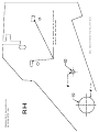
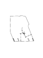
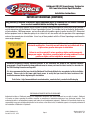
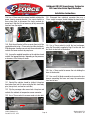
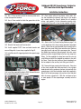
Edelbrock E-Force Supercharger
Grand Sport Corvette
Part #1574, 1575 & 1576
FOR VEHICLES NOT EQUIPPED WITH AUX. OIL COOLER,
DRILL HOLES MARKED B
FOR VEHICLES EQUIPPED WITH AUX. OIL COOLER,
DRILL HOLES MARKED A.
LH
A
1.00
A
B
A
0.35
1.00
A
0.35
B
LINE UP TEMPLATE TO SHROUD
USING THESE FEATURES
0.35
1.38
TEMPLATE, FAN SHROUD,
C6 CORVETTE, LH
RH
TEMPLATE, FAN SHROUD,
C6 CORVETTE, RH
A
1.38
0.35
A
DRILL HOLES MARKED A FOR ALL VEHICLES
LINE UP TEMPLATE TO SHROUD
USING THESE FEATURES
11
11
2
4
15 64
Edelbrock GM LS3 Supercharger System for
2010 and later Grand Sport Corvettes
Installation Instructions
INTRODUCTION
Thank you for purchasing the Edelbrock 6.2L GM Supercharger System for the Chevy Corvette. The Edelbrock E-Force
Supercharger System for the 2010 and later Grand Sport Corvette (not compatible with Z06, ZR1 or base models) utilizes
Eaton’s new Gen VI TVS Supercharger rotors, featuring a four lobe design with a full 160 deg. of twist for maximum flow,
minimum temperature rise, quiet operation, and the reliability for which Eaton is known. The Edelbrock Supercharger is a
complete system that maximizes efficiency and performance by minimizing air restriction into, and out of, the supercharger.
This results in maximum airflow, with minimal temperature rise and power consumption. The supercharger housing itself
is integrated into the intake manifold for a seamless design with minimal components, eliminating the possibility of vacuum
leaks between gasket surfaces. The system also utilizes a front drive, front inlet configuration giving it the shortest, least
restrictive inlet path on the market. The supercharger is inverted, expelling the air upward. Air pressure then builds in
the plenum, before being drawn down through each of two intercooler cores, oriented horizontally, next to, and below the
supercharger outlet. After passing through the intercooler cores, the air travels through the long 12” runners, which route
underneath the supercharger housing to the cylinder head ports, in a horizontal, nested configuration. The upper plenum
area is enclosed by a top cover that has been designed to provide an appealing and distinctive under-hood appearance.
This configuration allows for a compact package that can fit under the stock hood and cowl of the C6 Corvette, without
sacrificing runner length, or intercooler area. The E-Force supercharger features a uniquely styled plenum, and includes
matching side covers. The Edelbrock supercharger provides neck snapping performance that is safe to operate on a
completely stock engine. It is 50-state emissions legal, and can be had with an optional 5-year 100,000 mile warranty
so that there are no worries when installing it on a brand new car.
TOOLS AND SUPPLIES REQUIRED
l Jack and Jack Stands
OR Service Lift
l Panel Puller
l Ratchet and Socket Set including: 7mm, 8mm, 10mm
(standard, deep and universal), 11mm, 12mm (deep),
13mm, 15mm, 18mm, 21mm (deep), 24mm
l Wrenches including: 8mm, 18mm, 27mm
l 18mm Line Wrench
l 12” Ratchet Extension Bar
l 1/2” Breaker Bar
l Flat Blade & Phillips Screwdrivers
l Compressed Air
l Torx-20 Driver
l Allen Wrenches including: 5mm, 6mm, 8mm
l 5/8” Fuel Line Removal Tool
l Torque Wrench
l Needle Nose Pliers
lPliers
OR Hose Clamp Removal Tool
l Pneumatic or Power Drill
l Impact Wrench
l Loctite 609 Retaining Compound or equivalent
l O-ring Lube
lAnti-seize
l Masking Tape
l DT-47731 Transmission Cooler Quick Disconnect Tool
l J-42188 Ball Joint Separator
l J-42386-A Flywheel Holding Tool
Edelbrock LLC, 2700 California Street, Torrance, CA 90503
Toll-Free Tech Line: 1-800-416-8628
©2014 Edelbrock LLC
Part #1574, 1575, 1576
Page 1
Brochure #63-1574
Rev. 9/24/14 - QT
Edelbrock GM LS3 Supercharger System for
2010 and later Grand Sport Corvettes
Installation Instructions
IMPORTANT WARNINGS
Before beginning the installation, use the enclosed checklist to verify that all
components are present in the box then inspect each component for damage
that may have occurred in transit. If any parts are missing or damaged, contact
Edelbrock Technical Support (800-416-8628), not your parts distributor.
SPECIAL NOTE FOR OWNERS OF THE 1575 599HP KIT
If you have purchased the 599HP Complete supercharger kit P/N: 1575, then your system includes an upgraded
in-tank ZO6 fuel pump, to support the additional horsepower that this system provides over the standard, 554HP, kit
P/N: 1574. Installation of this pump is complex, and not something we recommend for the do it yourselfer. Edelbrock
strongly recommends that before beginning the install of your 1575 supercharger kit, you take the vehicle to a Chevrolet
dealership, or experienced Corvette repair facility, for installation of this pump, per the specified GM workshop manual
procedure. Once installed, you can follow these instructions to fully install the Edelbrock system.
NOTE: Competing systems often recommend, or utilize, voltage amplifiers for the purpose of increasing the output of
the stock fuel pump. While these systems do work, and will work in conjunction with the E-Force superchargers as
well, Edelbrock does not endorse their use, as they can significantly reduce the life of the stock fuel pump, resulting in
possible engine damage. Edelbrock strongly feels that the increased effort to install the upgraded, in-tank, ZO6 fuel pump
assembly, included in the 1591 kit, is the proper way to address the need for increased fuel volume.
WARNING: Installation of this supercharger will result in a significant change to the
performance characteristics of your vehicle. It is highly recommended that you take some
time to familiarize yourself with the added power and how it is delivered. This must be
done in a controlled environment. Take extra care on wet and slippery roads as the rear
tires will be more likely to lose traction with the added power. It is never recommended to
turn off your vehicles traction control system.
Proper installation is the responsibility of the installer. Improper installation will void all
manufacture’s standard warranties and may result in poor performance and engine or vehicle
damage.
Due to the complexity of the Edelbrock E-Force Supercharging system, it is recommended that this system only be
installed by a qualified professional with access to a service lift, pneumatic tools, and a strong familiarity with automotive
service procedures. To qualify for the optional supplemental warranty, it is necessary to have this system installed by a
Certified ASE Technician, GM Dealership, or an Authorized Edelbrock Installer. Failure to do so will void and/or disqualify
any and all optional supplemental warranties offered with this system. Please contact the Edelbrock Technical Support
department if you have any questions regarding this system and/or how your installer of choice will affect any warranty
coverage for which your vehicle may qualify.
©2014 Edelbrock LLC
Part #1574, 1575, 1576
Page 2
Brochure #63-1574
Rev. 9/24/14 - QT
Edelbrock GM LS3 Supercharger System for
2010 and later Grand Sport Corvettes
Installation Instructions
IMPORTANT WARNINGS (CONTINUE)
Any previously installed aftermarket tuning equipment must be removed and the vehicle returned
to an as stock condition before installing the supercharger.
Any equipment that directly modifies the fuel mixture or ignition timing of the engine can cause severe engine damage if
used in conjunction with the Edelbrock E-Force Supercharger System. This includes, but is not limited to: ignition boxes,
air/fuel controllers, OBDII programmers, and any other device that modifies signals to and/or from the ECU. Aftermarket
bolt-on equipment such as underdrive pulleys or air intake kits will also conflict with the operation of the supercharger
and must be removed prior to installation. Use of any of these products with the E-Force Supercharger could result in
severe engine damage.
91 octane or higher gasoline is required at all times. If your vehicle has been
filled with anything less, it must be run until almost dry and refilled with 91 or
higher octane gasoline twice prior to installation.
Failure to use the required 91 octane gasoline or higher could permanently
damage your engine. Any failures associated with not using premium 91 octane
gasoline or higher, will be ineligible for warranty repairs.
Edelbrock periodically releases improved versions of the calibration file found on the supplied handheld
programmer. Check the website, www.edelbrock.com, to ensure you have the latest version, as described in
the PCM Flashing Procedure on Page #10.
It is also recommended that you check the Edelbrock Tech Center Website for any updates to this installation
manual. Please refer to the lower right hand corner to verify that you have the latest revision of this
installation manual before beginning the installation.
Tech Center: http://www.edelbrock.com/automotive_new/misc/tech_center/install/index.php
EDELBROCK AUTHORIZED INSTALLER DISCLAIMER
Authorized installers of Edelbrock products are independent companies over which Edelbrock has no right of control. Edelbrock
LLC makes no claims regarding the abilities, expertise or competency of individual employees of any authorized installer. Each
authorized installer is an independent company and makes its own independent judgments. Edelbrock LLC specifically disclaims any
responsibility to any party including third parties for the actions, or the failure to act, of individuals, agents or a company authorized in
the installation of Edelbrock LLC products.
©2014 Edelbrock LLC
Part #1574, 1575, 1576
Page 3
Brochure #63-1574
Rev. 9/24/14 - QT
Edelbrock GM LS3 Supercharger System for
2010 and later Grand Sport Corvettes
Installation Instructions
INSTALLATION HARDWARE IDENTIFICATION GUIDE
Bag #1
(3x) - M8 x 1.25 x 20mm
Hex Flange Bolt
(1x) - M10 x 1.5 x 75mm Hex Flange Bolt
(2x) - M8 Washer
(1x) - M10 x 1.5 x 45mm Socket Head Bolt
(3x) - M8 x 1.25 x 90mm Hex Flange Bolt
(3x) - M6 x 1 x 16mm
Hex Flange Bolt
Bag #2
(1x) - Nylon Body Pin
(2x) - M6 x 1 x 20mm
Hex Flange Bolt
(1x) - M8 x 1.25 x 30mm
Hex Flange Bolt
(1x) - Lower Intercooler Reservoir Bracket
(2x) - 1/2” Hose Clamp
(1x) - Upper Intercooler Reservoir Bracket
©2014 Edelbrock LLC
Part #1574, 1575, 1576
Page 4
(6x) - 3/4” Hose Clamp
Brochure #63-1574
Rev. 9/24/14 - QT
Edelbrock GM LS3 Supercharger System for
2010 and later Grand Sport Corvettes
Installation Instructions
Bag #3
(11x) - M8 x 1.25 x 25mm
Countersunk Socket Head Bolt
(8x) - M6 x 1 x 45mm
Hex Flange Bolt
Bag #4
(4x) - M6 x 1 x 12mm
Socket Head Bolt
(4x) - M6 x 1 x 16mm
Button Head Bolt
(1x) - GM Factory Harmonic Balancer Bolt
(1x) - M16 x 2 x 120mm Hex Bolt
Ream Hole
Drill Hole
Bolt Hole
(1x) - 1/4” x 3/4” Steel Dowel
(1x) - Crank Pinning Drill Guide
(1x) - 15/64” High Speed Steel Drill Bit
(1x) - .2500” Reamer
©2014 Edelbrock LLC
Part #1574, 1575, 1576
Page 5
Brochure #63-1574
Rev. 9/24/14 - QT
Edelbrock GM LS3 Supercharger System for
2010 and later Grand Sport Corvettes
Installation Instructions
Bag #5
(1x) - Barbed Quick Connect Fitting
(1x) - Air Inlet Tube PCV Grommet
(2x) - Air Inlet Tube Retainer Grommet
Bag #6
(1x) - Coil Cover
Dipstick Grommet
(4x) - Coil Cover Bracket
(4x) - Coil Cover Retainer Stud
(4x) - Coil Cover Standoff
©2014 Edelbrock LLC
Part #1574, 1575, 1576
Page 6
Brochure #63-1574
Rev. 9/24/14 - QT
Edelbrock GM LS3 Supercharger System for
2010 and later Grand Sport Corvettes
Installation Instructions
HOSE IDENTIFICATION GUIDE
Reservoir to
Water Pump
Intercooler to Reservoir
Heat Exchanger to Intercooler
Water Pump to
Heat Exchanger
Valve Covers to
Dry Sump (rear)
Manifold to EVAP Solenoid
PCV
Brake Booster
Air Inlet to Dry
Sump (front)
EVAP Solenoid
to Firewall
AUX Dry Sump
& Tee
©2014 Edelbrock LLC
Part #1574, 1575, 1576
Page 7
Brochure #63-1574
Rev. 9/24/14 - QT
Edelbrock GM LS3 Supercharger System for
2010 and later Grand Sport Corvettes
Installation Instructions
DRY SUMP ROUTING GUIDE
2009 & Later
Vehicles Only
D
NOTE: The stock valley tray
baffle must be transferred to the
Edelbrock valley tray.
B
A
A: Air inlet to dry sump (Front)
B: Valve covers to dry sump (Rear)
C: PCV to fitting on bottom of air inlet, behind
throttle body.
D: Auxiliary hose & tee fitting: From auxiliary
dry sump tank to “B” hose.
C
©2014 Edelbrock LLC
Part #1574, 1575, 1576
Page 8
Brochure #63-1574
Rev. 9/24/14 - QT
Edelbrock GM LS3 Supercharger System for
2010 and later Grand Sport Corvettes
Installation Instructions
OIL COOLER GUIDE
o
o
o
o
o
o
o
o
3
Oil Cooler to Block Flex Hose & Convolute (1)
Oil Cooler Hard Line (2)
Oil Cooler Hard Line to Upper Radiator-Hose Hose (3)
Oil Cooler (4)
Oil Cooler Bracket (5)
Freeze Plug w/ Quick Connect Provision (6)
5/8” Hose to Block Freeze Plug Adapter (7)
Low Oil Cooler 90° Swivel, -8AN to 5/8” Fitting (8)
6
5
7
1
2
(Cooler installed and plumbed on an engine )
©2014 Edelbrock LLC
Part #1574, 1575, 1576
Page 9
8
4
Brochure #63-1574
Rev. 9/24/14 - QT
Edelbrock GM LS3 Supercharger System for
2010 and later Grand Sport Corvettes
Installation Instructions
Supercharger Installation
NOTE: It is very important to perform the PCM flashing
procedure prior to starting this installation. This will
prevent any major installation delays due to non-compatible
calibration files.
In the rare occurrence that you encounter an error message
during the PCM flashing procedure, please refer to Page 28,
titled E-mail Edelbrock Your Stock PCM Calibration.
WARNING: Battery must be sufficiently charged before
starting the PCM flashing procedure.
Only begin the PCM flashing procedure when you are
ready to install the supercharger. Once the PCM is
flashed, DO NOT START the engine until the installation
of the E-Force supercharger is complete.
1. Before starting the flash procedure, check the
Edelbrock website at:
(http://www.edelbrock.com/automotive/mc/
superchargers/support.shtml)
to confirm that you have the latest calibration file. Once
you have found the latest calibration file on the website,
power on the programmer. Press the left arrow and select
the “Device Info” option. Scroll down to “Tune Version”
and compare the tune number to the one on the website.
If they are different, download the new calibration file with
the supplied USB cable.
2. Put the car into ACC mode, but don’t start the vehicle.
3. Connect the supplied PCM cable on the handheld
programmer to the OBD-II connector located below the
steering wheel, and to the left of your knee.
4. Use the directional pad to highlight the Program
Vehicle option and press the Select button.
©2014 Edelbrock LLC
Part #1574, 1575, 1576
5. Use the directional pad to highlight the Pre-programmed
Tune option and press the Select button.
6. Read the disclaimer then press Select to continue.
7. Verify that the ignition is in the ‘Key On’ position and
that the engine is not running, then press Select.
8. Use the directional pad to highlight your vehicle and
transmission combination then press Select.
9. Use the directional pad to highlight the Begin Program
option then press Select.
10. Depending on your specific drivetrain configuration,
several separate operations may take place during this
step. Completion of each operation will cause the progress
bar to reset to zero.
11. DO NOT unplug the programmer until prompted.
12. Turn the vehicle off when prompted to do so by the
handheld programmer.
13. Read the parting message from programmer then
press Select to continue.
14. Unplug the programmer cable from the OBD-II port.
This concludes the PCM flashing procedure. DO NOT start
the engine until the supercharger installation is complete.
15. Use a 10mm socket to remove the negative and
positive battery terminals.
Page 10
Brochure #63-1574
Rev. 9/24/14 - QT
Edelbrock GM LS3 Supercharger System for
2010 and later Grand Sport Corvettes
Installation Instructions
16. Use a 13mm socket and an extension bar to loosen
and remove the battery hold down.
21. Pull back the inner fender well to access the two
bumper studs on each side. Use a 10mm deep socket to
remove the nuts.
17. Remove the battery and set it to aside.
18. Use a 7mm wrench to remove the four bolts retaining
fascia center.
19. Lift and support the front end of the vehicle using a
jack and appropriately load rated jack stands then loosen
and remove the lug nuts from both front wheels. Remove
the wheels and set them aside.
22. Disconnect the indicator and fog lamp electrical
connectors. 23. Remove the three screws and one body pin that retain
each front valance.
20. Use a panel puller to remove the 7 body pins on each
side that retain the inner fender wells. (Note: Some trim
packages use screws in place of pins along outer edge.)
24. Remove the five 7mm and two 10mm nuts retaining
the fascia from below. ©2014 Edelbrock LLC
Part #1574, 1575, 1576
Page 11
Brochure #63-1574
Rev. 9/24/14 - QT
Edelbrock GM LS3 Supercharger System for
2010 and later Grand Sport Corvettes
Installation Instructions
25. Remove four body pins (two on each side) by reaching
up through the bottom of the fascia.
30. Disconnect the PCV tube from the air inlet tube.
26. Place multiple layers of masking tape on the nose of
the hood as well as the portion of the front fascia directly
below the hood to protect from damage during removal.
31. Lift the airbox and resonator tube off the locator pins
and remove it and the air inlet tube as an assembly.
27. The sides of the fascia can be pulled away from the
clips holding it in place, then down off the studs. The
center section must be pulled up and over the nose section,
and the whole assembly pulled straight off and set aside.
32. Use a 16mm socket and a breaker bar to turn the
tensioner until the serpentine belt has enough slack to
remove it.
33. Remove coil covers from valve covers by lifting up and
working fuel line through slot on driver side.
28. Disconnect the Mass Airflow Sensor connector. 34. Disconnect the Electronic Throttle Control connector
on the passenger side of the throttle body.
35. Use a 10mm socket to remove the four bolts holding
in the throttle body and set it aside.
29. Use a flat head screwdriver to loosen the Throttle Body
to inlet tube worm clamp.
©2014 Edelbrock LLC
Part #1574, 1575, 1576
Page 12
Brochure #63-1574
Rev. 9/24/14 - QT
Edelbrock GM LS3 Supercharger System for
2010 and later Grand Sport Corvettes
Installation Instructions
36. Disconnect the ignition coil harness and O2 sensor
connectors then disconnect the spark plug wires from the
ignition coils. 41. Use a 10mm socket to remove the four fuel rail bolts.
37. Use a 10mm socket to remove the five bolts retaining
the coil bracket on each valve cover then remove both coil
bracket assemblies.
NOTE: You will also need to remove one 8mm manifold bolt
and bracket before removing the fuel rails.
42. Lift the injectors out of the manifold and work the rails
forward until they can be set aside.
43. Use an 8mm socket to loosen the two rear passenger
side manifold bolts. Slide the manifold cover out from under
the bracket that those bolts retain, and remove it. 38. Use a fuel line removal tool to disconnect the fuel line
from the rails using a shop rag to absorb excess fuel.
39. Disconnect and remove the hose connecting the
passenger and driver side valve covers to the rear dry sump
tank fitting. 44. Use a 10mm socket to remove the seven remaining
manifold bolts (out of ten).
45. Disconnect the EVAP solenoid electrical connector.
40. Disconnect all eight fuel injector connectors.
©2014 Edelbrock LLC
Part #1574, 1575, 1576
Page 13
Brochure #63-1574
Rev. 9/24/14 - QT
Edelbrock GM LS3 Supercharger System for
2010 and later Grand Sport Corvettes
Installation Instructions
46. Disconnect MAP sensor electrical connector.
50. Remove the intake manifold and disconnect the small
vacuum hose at the rear of the manifold next to the larger
brake booster hose. Leave this hose connected to the
firewall as it will be reused later.
51. Use masking tape to cover the exposed intake ports on
the cylinder head.
47. Disconnect the vacuum hose from the brake booster
fitting; it will be removed with the manifold.
52. Remove the o-ring port gaskets from the stock intake
manifold and set them aside for reuse later.
53. Use a 15mm socket to remove the two bolts retaining
the belt tensioner. 48. Disconnect and remove the two EVAP tubes located at
the front of the manifold.
54. Disconnect the oil pressure sensor electrical connector
at the rear of the valley plate.
55. Use a 27mm wrench to remove the oil pressure sensor
from the rear of the valley plate.
49. Disconnect passenger side PCV tube from valley
plate.
©2014 Edelbrock LLC
Part #1574, 1575, 1576
56. Clear engine valley of all debris then use a 13mm
socket to remove the 11 bolts retaining the valley plate and
remove it. Page 14
Brochure #63-1574
Rev. 9/24/14 - QT
Edelbrock GM LS3 Supercharger System for
2010 and later Grand Sport Corvettes
Installation Instructions
57. Use a small flathead screwdriver to remove the eight
O-ring seals from the stock valley plate and install them in
the new valley plate. Remove the bolts retaining the stock
oil baffle to the stock valley plate then use a small
screwdriver to pry off the baffle. Clean any remaining
silicone off the mating flange, apply fresh silicone then
install the stock baffle onto the underside of the new valley
plate using the stock bolts coated with blue LocTite.
64. Use the DT-47731 Transmission Cooler Quick
Disconnect Tool to detach two oil lines from the oil cooler.
65. Remove the two bolts on the driver side holding the oil
cooler to the shroud.
66. Remove the nut holding the oil cooler bracket to the
shroud and remove the cooler.
67. Trace the oil cooler lines back to the oil pan and
disconnect them, then remove the lines as a single
assembly. The bolts can then be discarded.
68. Remove the retaining body pin located on each side of
the radiator shroud. (Passenger side shown).
58. Apply anti-seize to the tapered surface beneath the
heads of the countersunk bolts supplied in Bag #3 and
install the valley plate with the stock perimeter gasket.
Tighten the bolts from the center out with a 5mm allen tool
then torque them to 18 ft-lbs in the same sequence.
59. Install the oil pressure sensor into the supplied valley
plate with thread sealant and and a 27mm wrench. Torque
the sensor to 15 ft-lbs.
69. Disconnect the ambient air temperature sensor and
remove the sensor clipped to passenger side of shroud.
60. Reconnect the oil pressure sensor electrical connector
at the rear of the valley plate.
61. Use a 15mm socket to remove the bolt retaining the
EVAP solenoid.
62. Use a 10mm socket to remove the four bolts (two on
each side) retaining upper radiator shroud and remove.
70. Reach up from below the car to remove the two
remaining body pins retaining the front radiator shroud then
remove the shroud by pulling it down and out.
it.
63. Drain the engine oil from the oil pan and remove the
oil filter.
©2014 Edelbrock LLC
Part #1574, 1575, 1576
Page 15
Brochure #63-1574
Rev. 9/24/14 - QT
Edelbrock GM LS3 Supercharger System for
2010 and later Grand Sport Corvettes
Installation Instructions
71. Disconnect the radiator fan electrical connector, then
use a 10mm socket to remove the two bolts retaining the
fan assembly. Pull the hoses from the six clips holding
them to the assembly and remove the fan from below.
72. Use a hand siphon to drain the power steering fluid
reservoir. 73. Disconnect the alternator electrical connector.
CRANK PINNING & OIL COOLER INSTALLATION
CRANK PINNING NOTE: Some of the following steps,
while not strictly related to installing the supercharger,
detail the process required for installing a lock pin between
the harmonic balancer and the crankshaft nose. The
factory design uses a press-on balancer that does not
include an anti-rotation mechanism to prevent the balancer
from loosening. The additional torque of the E-Force
system increases the likelihood of this occurring. Any
damage caused by failure to follow this procedure will not
be covered by the optional warranty. If you have already
had this procedure performed on your vehicle, skip steps
72-106 and 124-139.
OIL COOLER NOTE: Installation of oil cooler is explained
with in the crank pinning procedure as It is easiest to install
once the crank pinning procedure has been completed, but
before the steering rack and other parts are reinstalled.
If you have already had the crank pinning procedure
performed on your vehicle, then the Oil cooler installation
(Steps 107-123) can be performed after the supercharger
installation has been completed, albeit with a greater
degree of difficulty.
©2014 Edelbrock LLC
Part #1574, 1575, 1576
74. Use a 13mm socket to remove alternator power wire.
75. Use a 15mm socket to remove the two alternator
support bolts, and then remove the alternator.
WARNING: With the wheels of the vehicle facing straight
ahead, secure the steering wheel with a steering column
anti-rotation pin, steering column lock or strap. Failure
to do so may result in damage to or a malfunction of the
airbag deployment system.
76. Use an 11mm socket and an extension bar to remove
the bolt securing the steering column to the rack then pull
the intermediate shaft off the gear. Do not attempt to turn
the steering wheel until this bolt has been reinstalled. Page 16
Brochure #63-1574
Rev. 9/24/14 - QT
Edelbrock GM LS3 Supercharger System for
2010 and later Grand Sport Corvettes
Installation Instructions
77. Use a 6mm Allen tool to hold the tie rod ball stud
stationary while using an 18mm wrench to loosen the nut.
81. Use a 10mm socket to remove the two nuts retaining
the brake pressure modulator valve. 2008 Only
‘09 and Later
78. Use GM Ball Joint Separator #J 42188 to separate the
steering knuckle from the tie rod ball stud then remove the
tool and the nut. Use this procedure for both sides.
79. Remove the lower nut from the endlink by placing an
8mm wrench on the end of the stud while using an 18mm
wrench on the nut. Repeat this procedure on both sides.
82. Place a catch pan below the steering gear then use an
18mm line wrench to disconnect the two power steering
lines from the steering gear.
83. Use a 10mm socket to remove the bolts retaining the
power steering line brackets or fluid cooler, if equipped.
80. Use a 13mm socket to remove the four bolts retaining
the stabilizer brackets. 84. Use a floor jack to support the oil pan.
©2014 Edelbrock LLC
Part #1574, 1575, 1576
Page 17
Brochure #63-1574
Rev. 9/24/14 - QT
Edelbrock GM LS3 Supercharger System for
2010 and later Grand Sport Corvettes
Installation Instructions
85. Use a 21mm deep socket to remove the two front
engine cradle bolts. 90. Use an 18mm socket to remove the two steering rack
nuts and bolts.
86. Disconnect the ride height sensor electrical connector
from each side, if equipped. 91. Remove the plastic clamp holding the power steering
lines to the steering rack.
92. Loosen the rear engine cradle nuts with a 21mm deep
socket and lower them until there is a gap of 10mm from
the cradle to the top of the nut.
87. Use a 10mm socket to remove the driver side brake
line bracket bolt.
88. Use a 10mm socket to remove driver side ride height
sensor bolt.
89. Use a 13mm socket to remove the lower brake
modulator bracket bolts.
93. Insert a pry bar between the frame and front driver
side cradle mount.
94. Work the power steering rack out through the driver
side wheel well. Use the pry bar to widen the gap when
needed and push the brake lines out of the way to clear
the gearbox.
©2014 Edelbrock LLC
Part #1574, 1575, 1576
Page 18
Brochure #63-1574
Rev. 9/24/14 - QT
Edelbrock GM LS3 Supercharger System for
2010 and later Grand Sport Corvettes
Installation Instructions
NOTE: The following six steps detail the process needed
to loosen and remove the crank bolt. Manual vehicles have
the option of placing a passenger in the car to put the car
in first gear and apply firm brake pressure while turning
the crank bolt. Do not attempt this optional procedure if
the rear wheels are on the ground or vehicle damage and/
or injury could result.
98. Disconnect electrical connector at top of starter, then
use a 13mm socket to remove the nuts retaining power
wires to the starter.
95. Disconnect the oil level sensor electrical connector
from the passenger side of the oil pan.
99. Remove and set the starter and bracket aside.
100. Install GM Flywheel Holding Tool #J-42386-A to
prevent the crank from rotating while loosening the
balancer bolt and torque the bolts holding it to 37 ft-lbs.
96. Use a 10mm socket to remove the starter support
bracket bolt.
101. Use a breaker bar and a 24mm socket to loosen and
remove the crank bolt. A long pipe slid over the breaker bar
can be helpful for increasing leverage.
102. Mark off with a piece of masking tape 1.5” from the
tip of the supplied drill bit.
97. Use a 13mm socket to remove the two starter bolts.
103. Use a 24 mm socket to install the supplied bolt and
reamer guide to the end of the crank.
©2014 Edelbrock LLC
Part #1574, 1575, 1576
Page 19
Brochure #63-1574
Rev. 9/24/14 - QT
Edelbrock GM LS3 Supercharger System for
2010 and later Grand Sport Corvettes
Installation Instructions
104. Lubricate the 15/64” bit supplied in Bag #4 with
a small amount of engine oil, then drill into the guide
hole with a bushing until the tape mark on the bit meets
the guide. Loosen the bolt and blow out any chips with
compressed air then turn the guide until the ream hole
lines up with the one just drilled in the crank and balancer.
Use the back side of the ream tool to verify that the holes
line up then tighten the bolt and use the .2500” reamer to
ream the hole.
105. Use compressed air to clear out any metal shards in
the hole. Apply Loctite 609 retaining compound or
equivalent to the supplied crank pin then tap it into the
drilled hole until it is flush.
106. Install the supplied GM crank bolt into the crank and
torque it to 37 ft-lbs, then rotate it an additional 140°
NOTE: You may refer to the Oil COOLER Guide on Pg.9 for
identification and placement of the following components.
107. Remove the wire harness holding clamp from the gap
between the driver side motor mount and the block.
108. Remove the e-clips securing the stock oil lines to the
distribution block located directly above the oil filter then
pull out discard the stock oil lines.
109. Use a 10mm socket to remove the distribution block
from the side of the oil pan and discard it.
©2014 Edelbrock LLC
Part #1574, 1575, 1576
110. Use a 10mm socket to remove the two center oil pan
rail bolts.
111. Place a wide drain pan below the driver side of the
crossmember. Even if the coolant has been previously
drained, there will still be a significant amount remaining
in the block.
112. Use a 17mm Allen socket and a 1/2” breaker bar to
remove the threaded freeze plug located on the driver side
of the engine block near the front of the engine.
113. Install the supplied threaded fitting into the hole
previously occupied by the freeze plug.
114. Use a 13mm wrench to loosen the knock sensor then
re-clock it so that it will clear the new oil cooler. Tighten
the sensor back down once it is correctly positioned.
115. Install the male nipple fitting into the short rubber
hose and secure it with a spring clamp. Install the supplied
convolute over the hose then route it between the driver
side engine mount and the block and push the nipple into
the fitting in the block.
116. Attach the short section of the long molded hose to
the supplied hard line and secure it with a worm clamp.
117. Lower the newly assembled water line down near the
upper radiator hose and route it so that it will pass in front
of the steering rack and between the engine mount and the
block so that the fitting is near the oil filter.
118. Attach the bracket to the cooler using the supplied
bolts. Apply a dab of lube to the O-ring on the 90° swivel
fitting and insert it into the lower provision of the cooler.
Page 20
Brochure #63-1574
Rev. 9/24/14 - QT
Edelbrock GM LS3 Supercharger System for
2010 and later Grand Sport Corvettes
Installation Instructions
119. Attach the short water line from the block to the 90°
swivel fitting and secure it with a spring clamp. Make sure
the hose clamp is clocked outboard in such a way that it
won’t interfere with the installation of the hard line.
120. Push the fitting on the end of the hard line into the
upper provision of the oil cooler until it clips into place.
121. Mount the oil cooler to the oil pan and loosely install
the two supplied and two stock oil pan bolts. Tighten all
four mounting bolts and torque them to 18 ft-lbs.
128. Use a 10mm socket and the stock bolts to mount the
brake pressure modulator to the bracket and torque them
to 106 in-lbs.
129. Use a 10mm socket and the stock bolts to reinstall the
power steering line brackets.
130. Use an 18mm line wrench to reinstall the power
steering pressure and return hoses to the steering gear
then torque the fittings to 20 ft-lbs.
131. Use a 10mm socket to reinstall the driver side ride
height sensor then plug in the electrical connector.
132. Use a 13mm socket and the four stock bolts to
reinstall the stabilizer and the brackets supporting it then
torque the bracket bolts to 43 ft-lbs.
133. Use an 8mm and an 18mm wrench to reattach the
stabilizer bar end links to the control arms then torque the
nuts to 56 ft-lbs.
122. Install the large tee fitting on the upper end of the
molded rubber hose and secure it with a worm clamp.
Approximate the best location to remove a 1 inch segment
of the upper radiator hose to allow fitting installation.
123. Cut out the 1 inch segment of the upper radiator hose
previously identified and install both remaining ends onto
the tee fitting. It will be necessary to re-clock the
hose segment extending from the water pump outlet
in order to attach it to the tee fitting. Secure both ends
to the tee fitting with the supplied clamps.
124. Slide the steering rack back into place and reconnect
the electrical connector.
125. Use an 18mm socket to reinstall the steering rack
nuts and bolts then torque them to 74 ft-lbs.
134. Use a 6mm Allen tool and an 18mm wrench to
reattach the tie rod ends to the control arm. Tighten the nut
to 22 ft-lbs. then rotate it an additional 120°.
135. Reattach the steering column to the rack then use an
11mm socket to torque the stock bolt to 20 ft-lbs.
136. Reinstall the locating clamp around steering rack.
137. Reinstall the alternator, attaching the power wire and
electrical connector then torque bolts to 37 ft-lbs.
138. Insert starter support bracket and bolt it in place.
139. Reattach the starter electrical connector and the
power wires. Torque the power wire nuts to 71 in-lbs.
Reinstall the starter then use a 13mm socket to torque the
two bolts that hold it in place to 37 ft-lbs.
126. Reinstall the front crossmember nuts then use a utility
jack to lift the crossmember. Torque all four crossmember
nuts to 81 ft-lbs.
127. Use a 13mm socket and the stock bolts to reinstall
the brake modulator bracket then torque them to 20 ft-lbs.
©2014 Edelbrock LLC
Part #1574, 1575, 1576
Page 21
Brochure #63-1574
Rev. 9/24/14 - QT
Edelbrock GM LS3 Supercharger System for
2010 and later Grand Sport Corvettes
Installation Instructions
140. Apply blue loctite to the threads of a 20mm bolt
supplied in Bag #1, then use a 12mm socket and the
supplied washer to mount the pulley on the new lower idler
bracket and torque it to 18 ft-lbs.
141. Use a 10mm socket to remove the three bolts on the
passenger side of the water pump.
143. Use a 15mm socket and the two stock bolts to mount
the new tensioner bracket onto the water pump then torque
them to 37 ft-lbs.
144. Use an 8mm allen tool to install the 45mm bolt
supplied in Bag #1 that retains the tensioner bracket to the
cylinder head and torque it to 37 ft-lbs.
145. Apply blue loctite to the threads of a 20mm bolt
supplied in Bag #1, then use a 12mm socket and the
supplied washer to mount the pulley on the tensioner
bracket and torque it to 18 ft-lbs.
146. Use a 15mm socket and the 75mm bolt supplied in
Bag #1 to install supplied tensioner on new bracket and
torque it to 37 ft-lbs.
142. Use a 6mm Allen tool and the three 90mm bolts
supplied in Bag #1 to install the lower idler bracket on the
water pump then torque them to 18 ft-lbs.
147. Use a 12mm socket and a 20mm bolt supplied in Bag
#1 to mount the EVAP purge solenoid on the back of the
new tensioner bracket.
©2014 Edelbrock LLC
Part #1574, 1575, 1576
Page 22
Brochure #63-1574
Rev. 9/24/14 - QT
Edelbrock GM LS3 Supercharger System for
2010 and later Grand Sport Corvettes
Installation Instructions
148. Use a 15mm wrench to remove two bolts retaining the
power steering reservoir bracket. Use a pair of pliers or
hose clamp tools to disconnect the lower reservoir-topump hose. Note that it is not necessary to fully remove the
reservoir from the engine. 149. Slide the old bracket off the reservoir then install the
supplied bracket using a 15mm socket and the stock bolts.
Slide the power steering reservoir onto the new bracket and
reattach the lower reservoir to pump hose.
154. Disconnect horn electrical connector then use a
10mm socket to remove the bolt holding the horn bracket
in place. Remove the horn assembly and set it aside.
155. Use a 10mm socket to install the heat exchanger,
using the 20mm bolts supplied in Bag #2 on the side, and
the stock air dam bolt on the bottom. 150. Line up the supplied templates on the radiator shroud
and drill the appropriate holes, depending on the presence,
or absence, of the factory oil cooler. 156. Use a 10mm socket to remove the nuts holding the
horns to the bracket.
151. Reinstall the radiator shroud by sliding it into place
from below then hold it in place using the four stock body
pins (two up front, and one on each side).
157. Use a small flat blade screwdriver to remove the wire
harness connecting the horns and swap the connectors
from horn to horn.
152. Clip the passenger side sensor back into place and
reattach the ambient air temperature sensor connector.
153. Use a 10mm socket to remove center air dam bolt.
©2014 Edelbrock LLC
Part #1574, 1575, 1576
Page 23
Brochure #63-1574
Rev. 9/24/14 - QT
Edelbrock GM LS3 Supercharger System for
2010 and later Grand Sport Corvettes
Installation Instructions
158. Use a 12mm socket to install the water pump in its
bracket and secure it with the supplied strap.
NOTE: There are two different water pump brackets:
Version (1) requires the use of your OE horn bracket.
Version (2) has an integrated horn bracket. You should have
received one of the two brackets; If your supercharger kit
includes bracket version (2), you may disregard Step 161.
OE Horn brkt.
Version (1)
159. Remove the passenger side lower body pin.
Version (2)
161. NOTE: This step only applies to customers who
received version (1) of the water pump brackets. Install
the supplied stand-off and lock nut onto the OE horn
bracket. Proceed by mounting that assembly, with the
supplied M6 x 10mm bolt, to the water pump bracket as
shown below.
160. Use a 10mm socket to loosely install the water pump
bracket using the stock horn bracket bolt on top and the
bolt supplied in Bag #3 on the bottom. 162. Re-install the horns using the OE nuts. Be sure
to orient the horns so that there is slack in the horn’s
wiring harness. Warning: Do not mount the horns with
the openings facing up, as they may accumulate
condensation and cease working.
©2014 Edelbrock LLC
Part #1574, 1575, 1576
Page 24
Brochure #63-1574
Rev. 9/24/14 - QT
Edelbrock GM LS3 Supercharger System for
2010 and later Grand Sport Corvettes
Installation Instructions
163. Use the supplied bit to drill a 15/64” hole in the
passenger side of the upper radiator shroud according to
the supplied template. 164. Use a 10mm socket and the four stock bolts to
reinstall the upper radiator shroud then attach the relay off
the supplied water pump wire harness to the upper radiator
shroud using the supplied body pin. Open and close the
hood to verify the relay clears the hood strut.
166. Plug the male connector on the T-segment of the
harness into the EVAP solenoid then plug the factory EVAP
connector into the female connector on the T-segment.
167. Use a 10mm socket and the two stock bolts to
reinstall the radiator fan.
168. Attach the radiator fan electrical connector then push
the stock hoses back into the factory clips.
169. Install the short molded hose from the outlet of the
intercooler water pump to the heat exchanger inlet. Secure
the fittings with the supplied hose clamps. 165. Route the intercooler water pump wire harness
extending from the relay down to the intercooler water
pump and plug in the connector. 170. Lower the heat exchanger hose assembly along the
driver side of the radiator shroud.
©2014 Edelbrock LLC
Part #1574, 1575, 1576
Page 25
Brochure #63-1574
Rev. 9/24/14 - QT
Edelbrock GM LS3 Supercharger System for
2010 and later Grand Sport Corvettes
Installation Instructions
171. Connect the heat exchanger hose assembly to the
heat exchanger through the hole drilled in the shroud.
Secure the fitting with a hose clamp supplied in Bag #2.
176. Install the long end of the molded hose onto intercooler
reservoir outlet so that the hose extends out and then turns
down when the reservoir is held upright. Secure the hose
with a hose clamp supplied in Bag #2. Proceed by installing
the brackets supplied in Bag #2 with a 10mm socket, as
depicted below.
172. Connect TMAP harness to TMAP sensor near rear of
manifold. 177. Use a 10mm socket to loosen rear hood hold down
latch bolt on passenger side fender. 173. Reinstall the battery and secure it with the stock hold
down but DO NOT reconnect electrical terminals.
174. Use a 10mm socket and an extension bar to loosen
the two nuts securing the fuse box.
178. Install intercooler reservoir by working molded hose
down along the passenger side of the radiator to the water
pump inlet and secure the hose on the pump fitting with a
hose clamp supplied in Bag #2.
179. Slide intercooler reservoir brackets behind loosened
fuse box nut and hood hold down latch bolt. Use a 10mm
socket to torque them to 89 in-lbs.
180. Use a 10mm socket to mount fuse on fuse box stud.
175. Use a 7mm socket to remove the fuse box bolt located
in the passenger side fender well.
©2014 Edelbrock LLC
Part #1574, 1575, 1576
Page 26
Brochure #63-1574
Rev. 9/24/14 - QT
Edelbrock GM LS3 Supercharger System for
2010 and later Grand Sport Corvettes
Installation Instructions
181. Use a 13mm socket to attach the harness power wire
to the main positive terminal.
182. Use a 10mm socket to attach the ground wire to the
ground stud near the relay.
183. Reinstall the fender well fuse box bolt.
184. Install supplied 15/32” hose on brake booster and
secure fitting with a hose clamp supplied in Bag #2.
185.Install the stock O-ring port gaskets in the supercharger
manifold.
186. Install the supplied Manifold to EVAP Solenoid Hose on
the manifold fitting below the hub snout. ©2014 Edelbrock LLC
Part #1574, 1575, 1576
187. Clear engine valley of any hoses, wires, tools, etc.
Lay the intercooler-to-reservoir tank hose in the engine
bay, routed along the firewall behind the oil pressure
sensor, and connect it to the intercooler reservoir inlet,
securing the fitting with a hose clamp supplied in Bag #2.
188. (Refer to the Dry Sump Routing Guide on page 7 for
a clear depiction of the hose routing procedure described
below.) Attach the dry sump breather hose assembly to the
driver side valve cover fitting, then route the rest of the hose
along the firewall and over to the passenger side. Connect
the middle hose section to the passenger side valve cover
provision and the straight fitting to the rear dry sump tank
fitting. Cut the supplied dry sump hose near the rear dry
sump fitting and install the supplied tee adapter in line with
that hose. Route the short section of hose extending from
the tee adapter to the auxiliary tank fitting and attach it.
189. Remove the tape covering the intake ports. Since two
of the stock manifold bolt hole provisions in the cylinder
heads break into the crankcase and are not used with this
supercharger, install the two button head bolts supplied in
Bag #3 in the front passenger side and rear driver side bolt
holes to ensure a good seal. With the assistance of one
or more people, lift the supercharger assembly onto the
engine.
Page 27
Brochure #63-1574
Rev. 9/24/14 - QT
Edelbrock GM LS3 Supercharger System for
2010 and later Grand Sport Corvettes
Installation Instructions
190. Tilt the manifold back slightly to install the small
factory vacuum hose running from the driver side firewall
fitting on the small fitting on the driver side of the air inlet
and the brake booster hose onto the larger fitting then
secure the brake hose with a clamp supplied in Bag #2.
195. Apply O-ring lube to the sealing ring of the four
supplied fuel rail fittings. Use a 3/4” wrench to install the
two straight hose fittings on the radiator side of each fuel
rail then install the plug in the firewall end of the passenger
side fuel rail and the U-shaped fitting on the firewall end of
the driver side rail. Orient the fitting close to the injector,
leaving room for the injector connector.
196. Connect Manifold to EVAP Solenoid hose to the outer
EVAP solenoid fitting and EVAP Solenoid to Firewall Hose to
the inner EVAP solenoid fitting. Route Solenoid to Firewall
hose beneath hub snout and along driver side valve cover
to firewall fitting and connect it.
191. Use a 10mm universal socket with an extension bar
to install the eight intake manifold bolts following the torque
sequence below. Torque the bolts to 4 ft-lbs in the first
pass, then to 7.5 ft-lbs in the second. 197. Apply O-ring lube to the lower seals of each of the
fuel injectors.
192. Use a 3/8” Fuel Line Removal Tool to remove the fuel
input line from the firewall fitting.
193. Take the fuel injectors out of their boxes and remove
their protective covers.
194. Apply o-ring lube to the upper injector seals, then
slide the injectors into the rails so that the electrical
connectors face away from the mounting flange. ©2014 Edelbrock LLC
Part #1574, 1575, 1576
198. Attach the supplied fuel rail crossover line to the
fitting on the passenger side fuel rail.
199. Install the fuel rails by sliding the injectors down into
the manifold provisions and applying pressure until the
mounting holes in the rails line up with the manifold. Slide
the crossover hose under the snout and air inlet of the
supercharger as you install the passenger side rail then
connect it to the driver side fuel rail fitting.
200. Use a 5mm Allen tool to install four 12mm fuel rail
bolts supplied in Bag # 3 and torque them to 91 in-lbs.
Page 28
Brochure #63-1574
Rev. 9/24/14 - QT
Edelbrock GM LS3 Supercharger System for
2010 and later Grand Sport Corvettes
Installation Instructions
201. Clip the heat exchanger hose assembly to both lower
fittings at the front of the supercharger manifold.
202. Attach one end of the supplied PCV hose to the 90°
fitting below the air inlet on the supercharger. Route the
other end of the PCV hose to the tube extending from the
valley plate and attach
205. Use a small flathead screwdriver to remove the wire
covers at the back of the coil brackets. Note that you will
need to separate the covers from the bracket, then split the
two halves of the cover.
206. Tuck the fuel injector wiring harness and the EVAP
Solenoid to Firewall Fitting Hose under driver side coil
bracket then use a 10mm socket and the ten stock bolts to
install both coil brackets on to the valve covers.
207. Attach the ignition coil connectors and spark plug
wires to the coils.
208. Use a 10mm deep socket to remove the four stock
coil cover ball studs from the valve covers. 203. Install the supplied fuel line from the firewall fitting to
the U-shaped fitting on the driver side fuel rail.
209. Remove the grommets from the stock coil covers.
204. Connect fuel injector electrical connectors.
©2014 Edelbrock LLC
Part #1574, 1575, 1576
Page 29
Brochure #63-1574
Rev. 9/24/14 - QT
Edelbrock GM LS3 Supercharger System for
2010 and later Grand Sport Corvettes
Installation Instructions
210. Install the stock grommets into the coil cover brackets
supplied in Bag #6.
216. Route the serpentine belt according to the diagram.
Note that you must slide the belt around the bottom of the
bracket to get the belt on the lower passenger side idler
pulley.
211. Use a 10mm socket to remove the bolts securing the
#2, #3, #6 and #7 ignition coils.
212. Install the coil cover brackets on top of the ignition
coils, then use a 10mm socket to secure them with the
stock bolts.
217. Use a breaker bar and a 16mm socket to push the
tensioner enough to get the belt on, then double check the
routing.
218. Use a 10mm socket, an extension bar, the four stock
bolts and OEM seal to install the throttle body. Torque the
bolts to 91 in-lbs.
213. Tuck the wire harness tight against the fuel rails.
Verify that nothing will be pinched or damaged when the
coil covers are installed.
214. Use a 7/16” deep socket to install the four ball studs
supplied in Bag #6 onto the supplied coil covers.
215. Plug the OEM engine harness MAP sensor connector
into the supplied MAP harness then route the harness to the
vicinity of the air intake. ©2014 Edelbrock LLC
Part #1574, 1575, 1576
219. Connect ETC harness to the throttle body motor.
220. Connect the intercooler hose assembly to the two
upper hose fittings at the front of the manifold.
Page 30
Brochure #63-1574
Rev. 9/24/14 - QT
Edelbrock GM LS3 Supercharger System for
2010 and later Grand Sport Corvettes
Installation Instructions
221. Install the silicone inlet tube to the throttle body and
secure it with a supplied worm clamp. 226. Use a 3/32” Allen tool and bolts supplied in Bag #5 to
install the stock MAF sensor in the new air inlet tube.
227. Route the supplied MAF wire harness near the driver
side of the throttle body.
222. Install the grommet supplied in Bag #5 into the new
air inlet tube.
223. Install the hose barb supplied in Bag #5 into the new
air inlet tube.
224. Lower supplied air filter onto the radiator shroud.
228. Install the two supplied grommets into the ears of the
new air inlet tube.
229. Slide the nose of the air inlet tube into the air filter
then hold the grommets in place with a socket as you tilt
the air inlet tube down into the silicone tube and onto the
locator pins.
230. Connect the Air Inlet to Dry Sump hose to the air inlet
tube fitting, then route the hose along the passenger side
valve cover and connect it to the front fitting of the dry
sump tank.
225. Use a T20 Torx driver to remove the MAF sensor from
the stock airbox.
©2014 Edelbrock LLC
Part #1574, 1575, 1576
Page 31
Brochure #63-1574
Rev. 9/24/14 - QT
Edelbrock GM LS3 Supercharger System for
2010 and later Grand Sport Corvettes
Installation Instructions
231. Connect the MAF harness to the MAFS then connect
the OEM MAF connector to the supplied MAF harness.
242. Reinstall the front wheels and torque the lug nuts in a
crossing pattern to 100 ft-lbs.
232. Rotate the worm clamps so that the gears are on the
driver side then secure the air inlet tube by tightening the
worm clamps on the air filter and the silicone hose.
243.Reconnect the battery and switch ignition to the ON
position, DO NOT START. With the ignition switch on,
check for any coolant or fuel leaks. Repair all leaks before
proceeding. If no leaks are present the installation is
complete.
233. Use a 5/8” wrench to install the coil cover stands
supplied in Bag #6 onto the valve covers. 244. Install the coil covers by sliding them into place and
pressing the ball studs into the bracket grommets.
Congratulations on the installation of your new Edelbrock
E-Force Supercharger System. If you have any questions,
please call our Technical Support hotline and one of our
technicians will be happy to assist you.
234. Use a 10mm socket to reconnect the positive battery
terminal.
235. Use a 10mm socket to reconnect the negative battery
terminal.
236. Remove intercooler reservoir cap and fill intercooler
system with a 50/50 blend of water and coolant.
237. Refill the power steering reservoir with power steering
fluid.
238. Reinstall the front fascia and reconnect the fog lamp
and indicator light electrical connectors.
239. Secure the front fascia with the stock hardware,
including the four bolts under the hood, the two nuts on
each fender, the five bolts and two nuts on the underside
and the four body pins that clip into the radiator shroud.
Refer to steps #18-24 for fastener locations.
240. Reattach the front valances using the three stock
screws and one body pin on each side.
241. Secure the front inner fender wells with the stock
fasteners.
©2014 Edelbrock LLC
Part #1574, 1575, 1576
Page 32
Brochure #63-1574
Rev. 9/24/14 - QT
Edelbrock GM LS3 Supercharger System for
2010 and later Grand Sport Corvettes
Installation Instructions
E-mail Edelbrock Your Stock Vehicle Calibration
In the rare occurrence that you encounter an error message that reads “Calibration not supported” during
the PCM flashing procedure on page 10, you will need to e-mail your stock vehicle calibration to Edelbrock
at [email protected]. Otherwise, disregard this step.
• Begin by downloading the SCT device updater software to your computer; it can be downloaded from: http://www.
sctflash.com/software/SCTDeviceUpdater.exe • Put the car into Acc mode but do not start it. • Connect the supplied PCM cable from the tuner to the OBD-II connector. • Select PROGRAM VEHICLE, arrow over to UPLOAD STOCK, press SELECT and follow the prompts on the
screen. • If the upload fails, you will be asked to AUTO DETECT, press SELECT and follow the prompts on the screen. If the auto
detect fail, then please contact Edelbrock Tech support @ 800-416-8628
• Once the stock calibration has loaded, disconnect the programmer from the OBD-II connector and connect it to your PC
using the supplied USB cable. • Open the SCT software and select the button on the lower left hand side that reads GET STOCK FILE FROM DEVICE.
Follow the instructions on the screen. • Once the download is complete, e-mail the file to [email protected] or call 1-800-416-8628 and our tech
support staff will assist you in e-mailing the file.
NOTE: The subject line of your e-mail should be “file update needed”, The file will automatically be labeled using your
VIN # followed by “.sul “ (XXXXXXXXXXXXX.sul)
• Once we have this file we can update the tune to work with your application, then we will e-mail you the custom tune
which you may use until the release version is available. (This process can usually be completed within 1 to 2 business
days)
• Download the new tune to the programmer using the directions received with the custom tune.
• Re-try the test flash procedure using the custom tune.
©2014 Edelbrock LLC
Part #1574, 1575, 1576
Page 33
Brochure #63-1574
Rev. 9/24/14 - QT