1
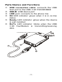
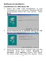
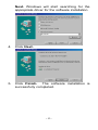
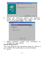
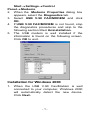
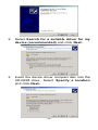
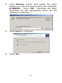
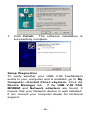
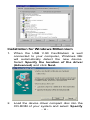
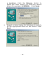
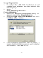
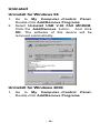
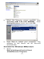
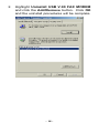
Bausch Proxima USB Lite Fax/Modem User Manual Introduction The USB V.90 Fax/Modem complies with the Universal Serial Bus functionality built in Windows 98/2000/Millennium. It is compatible with Bell, ITU-T (formerly CCITT) and Hayes AT commands. With this USB V.90 Fax/Modem, you can enjoy all the benefit offered by USB technology and get a faster and easier Internet access. Specifications Modem V.90, K56flex 56Kbps, V.34+ 33.6Kbps, V.34 28.8Kbps, V.32bis 14.4Kbps V.42bis/V.42, MNP 2-5 data compression and error correction AT command set Fax G3, V.17 14400bps, V.29 9600bps, Fax Service Class 1 compliant System Requirements § § § § § A Pentium processor-based personal computer 166MMX or above At least 16 MB of RAM An USB port Microsoft Windows 98/2000/Millennium A CD-ROM drive -1- Parts Names and Functions • USB connection cable: connects the USB host port to the USB V.90 FAX/MODEM ‚ USB-B: USB device port ƒ LINE jack: connects to the phone line „ OH LED indicator: glows when it is in on-line status … Ready LED indicator: glows when the device is well installed † Rx/Tx LED indicator: blinks when the USB V.90 Fax/Modem is transmitting/receiving data connects to the USB host port 6 5 4 1 3 2 -2- Hardware Installation 1. 2. 3. Locate the USB host port of your system. Connect one end of the USB connection cable to your USB host port. Connect the other end of the USB connection cable to the device port (USB B) of the USB V.90 Fax/Modem until it clicks. Connect your phone line to the LINE jack. -3- Software Installation Installation for Windows 98 1. When the USB V.90 Fax/Modem is well connected to your computer, Windows 98 will automatically detect the new device. Click Next. 2. Select Search for a suitable driver for my device (recommended) and click Next. 3. Insert the CD-ROM location. the drive device driver compact disc into the drive and select Specify a Click Browse button and select where you load the device. Click -4- Next. Windows will start searching for the appropriate driver for the software installation. 4. Click Next. 5. Click Finish. The software installation is successfully completed. -5- 6. When the following dialog box appears, select the country/location where you are, and click Enable PBX. Click OK. 7. When finished, restart your computer to activate the new device. Setup Diagnostics You can perform the following steps to check if your USB V.90 Fax/Modem is well installed. 1. Go to -6- Start→ → Settings→ → Control Panel → Modems. 2. When the Modems Properties dialog box appears, select the Diagnostics tab. 3. Select USB V.90 FAX/MODEM and click OK. 4. If USB V.90 FAX/MODEM is not found, stop the diagnostics procedures and skip to the following section titled Uninstallation. 5. The USB modem is well installed if the information is found on the following screen. Click OK to exit. Installation for Windows 2000 1. When the USB V.90 Fax/Modem is well connected to your computer, Windows 2000 will automatically detect the new device. Click Next. -7- 2. Select Search for a suitable driver for my device (recommended) and click Next. 3. Insert the device driver compact disc into the CD-ROM drive. Select Specify a location and click Next. -8- 4. Click Browse button and select the drive where you load the device driver (for example: E:\WIN2K). Click OK. Windows will start searching for the appropriate driver for the software installation. 5. Click Next to continue. 6. Click Yes. -9- 7. Click Finish. The software installation is successfully complete. Setup Diagnostics To verify whether your USB V.90 Fax/Modem exists in your computer and is enabled, go to My Computer→Control Panel→ → System. Click the Device Manager tab. If the USB V.90 FAX MODEM and Network adapters are found, it means that your Network device is well installed. If not, consult your computer dealer for technical support. - 10 - Installation for Windows Millennium 1. When the USB V.90 Fax/Modem is well connected to your computer, Windows ME will automatically detect the new device. Select Specify the location of the driver (Advanced) and click Next. 2. Load the device driver compact disc into the CD-ROM of your system and select Specify - 11 - a location. Click the Browse button to select the drive where you load the device driver (for example: G:\WIN98). Click Next. 3. Expect a minor delay for Windows to search for the appropriate driver for the device. Click Next. - 12 - 4. Click Finish. 5. When Windows prompt you “Modem Country Selection”, choose the country where you locate. Select the Enable PBX check box and click OK. The software installation is then complete. - 13 - Setup Diagnostics 1. To verify if the USB V.90 Fax/Modem is well installed and enabled, you can perform the following steps. 2. Go to Startà à Settingsà à Control Panel à Modems. 3. When the Modems Properties dialog box appears, select the Diagnostics tab. 4. Highlight USB V.90 FAX MODEM and click the More Info… button. 5. If the following information can be found, it means that the USB modem is well installed and enabled. Click OK to exit. - 14 - - 15 - Uninstall Uninstall for Windows 98 1. 2. Go to My Computer→Control Panel. Double-click Add/Remove Programs. Select Uninstall USB V.90 FAX MODEM. Click the Add/Remove button. And click OK. The software of this device will be removed automatically. Uninstall for Windows 2000 1. Go to My Computer→Control Panel. Double-click Add/Remove Programs. - 16 - 2. When the following screen appears, click Uninstall USB V.90 FAX MODEM. Click Change/Remove button and click OK. 3. Click Yes to restart your computer. The software of this device will be removed automatically. Uninstall for Windows Millennium 1. Go to Startà à Settingsà à Control Panel à Add/Remove Programs. - 17 - 2. Highlight Uninstall USB V.90 FAX MODEM and click the Add/Remove button. Click OK and the uninstall procedures will be complete. - 18 - Internet Access 1. 2. 3. Go to My Computer. Select Dial-Up Networking. Double-click Make a New Connection, a dialogue box will appear for you to name the new connection and select the device. Name the new connection appropriately and click Next. 4. Enter the area code and phone number of your Internet Service Provider (ISP). Follow the on-screen instructions to proceed. When finished, from the Dial-Up Networking window, right-click your newly created connection. Select Properties. On the Server Types tab, enter the proper selections as shown below and click OK to finish the settings. 5. - 19 - 6. For Windows Millennium, the figure above should be displayed as follows. 7. Now, you are ready to connect to the Internet. - 20 - Trouble Shooting This chapter provides information on the most commom problems, the possible causes, and the solutions. The modem does not respond to AT commands. § Conflict of COMx: port setting with another device. Change the COMx: port of the USB 56K FAX/MODEM to a free port. Be sure to update your software COMx: port setting as well. The modem does not execute the command line. § Make sure you are typing 'AT' at the beginning of command line. § Make sure the modem is not in Data Mode. type +++ if necessary. § Make sure your software is set to the same COMx: port as the modem is. The modem does not give a response after an AT command was executed. § The echo and/or responses may be turned off by the ATE0Q1 commands. Use AT&V to check that. Use ATE1Q0 then Enter to change them back. § Make sure the modem is in Command Mode rather than in Data Mode when you type the AT command. The modem gives an 'ERROR' response after an AT command was executed. § Make sure you did not type an invalid command. - 21 - § Make sure your command characters or less in length. line is 40 The modem goes off-hook and disables the telephone line. § The modem may be set to auto-answer mode when it rings. Typing ATS0=0, then Enter at the command line to disable the auto-answer mode. The modem does not auto-answer the phone. § Make sure the software is configured to autoanswer the phone. Type ATS0=n then press Enter. The n stands for the number of rings the modem will answer on. The software does not control the modem properly or can not detect the modem. § Make sure the software has been set up correctly. Check the initialization and dial strings. § Some TSRs (programs that stay in memory after they are loaded) may conflict with the communications software. Restart your computer without loading any TSRs. The characters on the screen are doubled. § Both the modem and the software have the echo feature turned on at the same time. Turn off the software echo feature off. § The remote modem is echoing your typed characters. Type ATE1 then Enter at the command line. Then turn off the software echo feature. No text appears on the screen when in data mode. - 22 - § The remote modem is not echoing your typed characters. Type ATE0 then press Enter at the command line. Then turn the software echo feature on. § Your software may not be set to use Full Duplex or the remote modem may not be set to use Full Duplex either. § C:The remote modem may be waiting for you to type a command before it will reply with text. No text appears on the screen when in command mode. If you can't see the characters you are typing, then type ATE1 then press Enter. The modem does not dial a phone number after you execute the AT dial command. § If you are using touch tone dialing on a phone line that requires pulses, then it may not work. Use ATDT in place of ATDP. When your communications software tells the modem to dial, it does not. § Make sure the software dialing prefix is ATDT. § Make sure the software and modem are set to the same COMx: port. § The modem may not have hung up the phone line since the last call. Change to command mode and type ATH then press Enter. When dialing another modem, you receive a 'CONNECT' response, but nothing else. - 23 - § The remote modem may be waiting for you to type a command. Or try to press Enter for logging on to the remote site. The modem speaker does not make any sound when you're connecting to another modem. The software may have the speaker disabled. Change the setting in your software or use the ATMn command to turn the speaker on. The modem disconnects (looses the connection) in the middle of use. § The remote modem may have locked up. § The telephone switch may have disconnected your call. § Your software may have turned off the DTR signal. The modem does not connect with another modem. § There may be a problem with the remote modem if you do not hear the high pitched tone from the remote modem. Occasionally, the modem gives a burst of errors. § The telephone line may be noisy or bad. Hang up the call and try to connect again for getting a better telephone line. § If there are other telephones on the same line that your modem is using, someone may have picked up a telephone on that extension. § Your telephone line may have the call waiting feature. - 24 - Try adding '*70,' to your ATDT dialing command line. If it doesn’t help, ask your telephone company how to disable it temporarily. The modem gets errors in transmitted data randomly. Try to use V.42 or MNP1-4 if possible. Connect the modems at a slower baud rate. After you download a file, it was not stored on your disk drive. § If both modems are using MNP or V.42 protocol, then the flow control may not be enabled. Configure your software to use RTS/CTS flow control. That will cause your computer to pause long enough for the file to be stored to disk. The text on the screen is not legible. § Your software settings may not match the settings on the remote site. Make sure your data bits, stop bits, and parity settings match the settings that the other computer is using. The two most common settings are: 8 data bits, None parity, and 1 stop bit (8,N,1) or 7 data bits, Even parity, and 1 stop bit (7,E,1). § If the telephone line is very noisy, you may see corrupted data on your screen. § Due to poor telephone line conditions, the modem may have fallen back to a slower communication speed. You may need to change the baud rate setting in your software to match this slower speed. To return the modem to the higher speed, disconnect the link and re-establish again. - 25 - When using V.42bis or MNP5, some features are disabled. § You may be using a non-streaming protocol, like Xmodem or Ymodem to transfer files. Those are fine unless you are using V.42bis or MNP5 When using V.42bis or MNP5, you should use a streaming transfer protocol like Ymodem-G or Zmodem. Configure your software to use hardware flow control (RTS/CTS ON). When the modem is connecting to another modem, it reports a higher connect baud rate that it is really using. § The modem defaults to report the modem-tocomputer baud rate when it responds with CONNECT. Go to command mode with your communication program (like Telix) and type ATW2, then press Enter. This tells the modem to report the modemto-modem baud rate instead - 26 - Appendix A: AT Commands Set Basic AT Commands A/ Re-execute Command The modem repeats the last command line sent by the DTE. Usually used for re-dialing. Note: This command should not be terminated by <CR>. A Answer The modem will go off-hook and attempt to answer an incoming call. Upon successful completion of handshake, the modem will go online in answer mode. Notes: If +FCLASS=0 is selected, the modem will enter the connect state after exchanging carrier with the remote system. If no carrier is detected within the period specified in S7, the modem hangs up. Any character entered while connecting will abort the connection process. If +FCLASS=1, the modem will go off-hook in V21 answer mode. It will generate the V21 2100 Hz answer tone for 3 +/- 0.5 seconds, and following a delay of 70 ms, will proceed as if the +FTH=3 command were issued. At any stage up to (but excluding) the +FTH=3 command state, any character will abort the communication. If +FCLASS=8 (#CLS=8), the modem will go offhook and a voice session will take place. Related S-Reg: S0 Bn CCITT Control - 27 - B0 Connect at V.22 1200 bps Result codes: Dn OK n=0 Error Otherwise Dial Directs the modem to go on-line, dial according to the string entered, and attempt to establish a connection. The Dial String may consist of any of the characters described below: * T Tone dialing (first character in the string) P Pulse dialing (first character in the string) L Redial last dialed number (first character in the string) 0-9 Digits 0 to 9. * Asterisk (tone only) # Hash (tone only) W Wait for dial tone; the modem will wait for dial tone before dialing the digits following “W”. S6 register will be used for timeout. (X3 or higher) , (Comma); Pause for the time specified by S8 before resuming the dialing ; (Semicolon) Return to command mode after dialing. This allows the user to issue additional AT commands while remaining off-hook. Actual call progress will be entered only after a dial command issued without the “;” terminator. S=n Dial the number stored in the directory; n=0-3 (see &Z). - 28 - ! Flash; The modem will go on hook for a time defined by S24. @ Wait for silence; The modem will wait for at least 5 seconds of silence before resuming the dialing. If no such silence is detected before the expiration of the call abort timer (S7), the modem will terminate with NO ANSWER response (or BUSY if applicable). If answer tone arrives during execution of this parameter, the modem handshakes. (X3 or higher) (),< > (space) String format characters ignored <i> any other character - ignored. Notes: If +FCLASS=0 is selected, the modem will attempt to connect with another data modem. The modem will use the time period specified in S6 and S7 as time-outs in the handshake process. If a timeout expires, the modem will go on-hook and respond with NO CARRIER response. The command will be aborted in progress is a DTE character is entered before completion of the handshake. If +FCLASS=1, the modem will attempt to connect with a fax machine (or modem) by entering the HDLC V21 channel 2 receive state (as if +FRH=3 had been issued). The command will be aborted upon receipt of a DTE character if the modem has not finished dialing. In this case the modem will go on-hook and return to command mode responding with NO CARRIER message. If the modem has finished dialing, It proceeds as if +FRH=3 command has been issued. - 29 - If +FCLASS=8 (#CLS=8), the modem will go offhook in V21 answer mode. It will decide (based on timers) when the other side answers in voice and a voice session will take place. Related S-Reg: S5,S6,S7,S16,S22,S28,S56 En Set local echo The modem enables/disables echo of characters to DTE. Parameter value is written to S13. * E0 Disable command echo. E1 Enable command echo. Result codes: OK n=0 or 1 Error Otherwise Related S-Reg: S13 Hn * Set ON/OFF hook H0 Modem hangs up (goes on-hook). H1 Modem goes off hook. Result codes: In OK n=0 or 1 Error Otherwise Identification/Information I1 Modem Name, Vendor Name, Modem Version, for example : ModemX ModemWorks Ltd. Ver 1.10 - 30 - I2 SW Provider /SW Version, for example Smart Link Ltd. Ver 1.20 I3 Chipset Vendor/Chipset ID, for example Chip Vendor Ltd. XY4220 I4 Modem active profile for example, Active Profile: S00=000 S01=000 S02=000 S03=000 S04=000 S05=000 S06=000 S07=000 S08=000 S00=009 S10=000 S11=000 S12=000 S13=000 S14=000 S15=000 S16=000 S17=000 S18=000 S01=019 S20=000 S21=000 S22=000 S23=000 S24=000 S25=000 S26=000 S27=000 S28=000 S29=000 S30=000 S31=000 S32=000 S33=000 S34=000 S35=000 S36=000 S37=000 S38=000 S39=000 S40=000 S41=000 S42=000 S43=000 S44=000 S45=000 S46=000 S47=000 I5 Stored profile 0 Active Profile 0: (Same format as above) I6 Stored profile 1 Active Profile 1: - 31 - (Same format as above) I7 Display stored pone numbers (See &Z command) Ln Speaker volume Select speaker volume. * L0 Low L1 Low L2 Medium L3 High Result codes: OK n=0-3 Error Otherwise Related S-Reg: S30 Mn Speaker control Select when the speaker is On/Off. * M0 Speaker always OFF M1 Speaker ON from start of dialing until receiving carrier M2 Speaker always ON M3 Speaker OFF from end of dialing until receiving carrier Result codes: OK n=0-3 Error Otherwise Related S-Reg: S29 - 32 - Nn Automode control Enable/Disable Automode detection. N0 Automode detection disabled. A subsequent handshake will be conducted according to the contents of S32. N1 Automode enabled. A subsequent handshake will be conducted according to the Automode algorithm. * Result codes: OK n=0 or 1 Error Otherwise Related S-Reg: S31 On Returns to on-line data mode This command is normally used to connect the DTE back after an escape (+++) has been issued. O0 Return to on-line data mode. O1 Return to on-line data mode, retrain first. Result codes: P OK n=0-1 Error Otherwise Pulse dialing Forces pulse dialing. Applies to subsequent dialing commands. This command holds until the next T dial modifier or T command is received. The modem will go off hook and attempt to answer an incoming call. Upon successful completion of handshake, the modem will go online in answer mode. - 33 - Related S-Reg: S16 Q Quiet result codes control * Q0 Enable sending result codes to DTE. Q1 Disable sending result codes to DTE. Result codes: OK n=0 or 1 Error Otherwise Related S-Reg: S14 S Read/Write S-Register This command has a few derivatives: Sn=v Sets the value v (decimal) to S-register n (v=0-255) Sn? Displays the value of S-register in decimal format (3 digits) Note: Some registers are read-only Result codes: T OK All parameters valid Error Invalid S register or value. Trying to write to a read-only register Tone dialing Forces tone dialing. Applies to subsequent dialing commands. This command holds until the next T dial modifier or T command is received. This command changes S14 to reflect the current dialing mode. - 34 - Related S-Reg: S16 Vn Verbose/Numeric result codes Select the time of result messages sent to the DTE. * For a list of result codes and verbal messages see X command. V0 Short form (numeric) result codes to be sent to DTE. V1 Long form (verbose) result codes to be sent to DTE. Result codes: OK n=0 or 1 Error otherwise Related S-Reg: S15 Xn Extended result codes Select the subset of result codes to be used by the modem to the DTE. If the modem is in fax mode (+FCLASS=1), the only message sent to indicate connection is “CONNECT” without a speed indication. X0 Supported messages: OK, CONNECT, RING, NO CARRIER and ERROR, Blind call enabled. X1 Supported messages: OK, CONNECT xxxx, RING, NO CARRIER and ERROR, Blind call enabled. - 35 - * X2 Same as X1 + NO DIAL TONE message, Blind call disabled X3 Same as X1 + BUSY message, Blind call enabled. X4 All messages supported, Blind call disabled (see list below). Notes: W,@ dial modifiers are ignored in X1, X2 S6 (Wait before dial) is ignored in X2, X4 if no W is specified in dial string S6 is set to 0 means a blind call - 36 - Result Codes Result Message Code X0 X1 X2 X3 X4 0 OK * * * * * 1 CONNECT * * * * * 2 RING * * * * * 3 NO CARRIER * * * * * 4 ERROR * * * * * 5 CONNECT 1200 1 * * * * 6 NO DIAL TONE 3 3 * 3 * 7 BUSY 3 3 3 * * 8 NO ANSWER 3 3 3 * * 9 CONNECT 0300 1 * * * * 10 CONNECT 0600 1 * * * * 11 CONNECT 2400 1 * * * * 12 CONNECT 4800 1 * * * * 13 CONNECT 7200 1 * * * * 27 CONNECT 9600 1 * * * * 14 CONNECT 12000 1 * * * * 15 CONNECT 14400 1 * * * * 16 CONNECT 16800 1 * * * * 17 CONNECT 19200 1 * * * * 18 CONNECT 21600 1 * * * * 19 CONNECT 24000 1 * * * * 20 CONNECT 26400 1 * * * * 21 CONNECT 28800 1 * * * * 22 CONNECT 31200 1 * * * * 23 CONNECT 33600 1 * * * * 24 CONNECT 34800 1 * * * * 25 CONNECT 40000 1 * * * * - 37 - 26 CONNECT 42000 1 * * * * 28 CONNECT 44000 1 * * * * 29 CONNECT 46000 1 * * * * 30 CONNECT 48000 1 * * * * 31 CONNECT 50000 1 * * * * 32 CONNECT 52000 1 * * * * 33 CONNECT 54000 1 * * * * 34 CONNECT 56000 1 * * * * 35 1 * * * * 36 CONNECT 57600 CONNECT 115200 1 * * * * 37 CONNECT 230400 * * * * 38 CONNECT 460800 1 * * * * 39 CONNECT 921600 1 * * * * 40 CONNECT 32000 * * * * 41 CONNECT 34000 1 * * * * 42 CONNECT 36000 1 * * * * 43 CONNECT 38000 * * * * * 44 CONNECT 58000 * * * * * 45 CONNECT 60000 * * * * * 46 CONNECT 28000 * * * * * 47 CONNECT 29333 * * * * * 48 CONNECT 30666 * * * * * 49 CONNECT 33333 * * * * * 50 CONNECT 34666 * * * * * 51 CONNECT 37333 * * * * * 52 CONNECT 38666 * * * * * 53 CONNECT 41333 * * * * * 54 CONNECT 42666 * * * * * 55 CONNECT 45333 * * * * * 56 CONNECT 46666 * * * * * - 38 - 57 CONNECT 49333 * * * * * 58 CONNECT 50666 * * * * * 59 CONNECT 53333 * * * * * 60 CONNECT 54666 * * * * * 70 FAX * * * * * 71 DATA * * * * * 100 VCON 4 4 4 4 * 101 DELAYED 4 4 4 4 * 102 BLACKLISTED 4 4 4 4 * 66 COMPRESSION: CLASS 5 - * * * * 67 COMPRESSION: V.42BIS - * * * * 69 COMPRESSION: NONE - * * * * 76 PROTOCOL: NONE - * * * * 77 PROTOCOL: LAPM - * * * * 78 PROTOCOL: MNP - * * * * 1021 MODULATION: V.21 - * * * * 1022 MODULATION: V.22 - * * * * 1032 MODULATION: V.32 - * * * * 1034 MODULATION: V.34 - * * * * 1103 MODULATION: B103 - * * * * 1122 MODULATION: V.22BIS - * * * * 1132 MODULATION: V.32BIS - * * * * - 39 - 1134 MODULATION: V.34BIS - * * * * 1212 MODULATION: B212 - * * * * +F4 +FCERROR * * * * <*> message will be generated when n has been selected <i> message will be replaced by message <I> when n has been selected <-> message will not be generated when n has been selected. * Related S-Reg: S56 Yn Select default configuration Select the default user defined configuration. Note: The default configuration is not loaded by Yn (See Zn) * Y0 Select user template 0 Y1 Select user template 1 Y2 Select factory setting 0 Y3 Select factory setting 1 Related S-Reg: S161 Zn Select user defined configuration Select the user defined configuration. Z0 Select default user template (as defined by Yn) Z1 Select user template 0 Z2 Select user template 1 Z3 Select factory setting 0 (&F0) Z4 Select factory setting 1 (&F1) Result codes: - 40 - OK n=0-5 Error Otherwise Related S-Reg: S59 AT& Commands &An Connect message format Select the format of the CONNECT message. * &A0 &A1 no extra messages besides CONNECT xxxxx Add Modulation indicator: V.21/ V.22/ V.22BIS/ V.32/ V.32BIS/ V.34/ V.34BIS/ B103/ B212 For example: Modulation: V.34 &A2 Add Error Detection Protocol and Data Compression indicators. For example: Protocol: LAPM/MNP/NONE Compression: CLASS 5/V.42BIS/NONE &A3 Add Modulation Indicator + Error Detection Protocol + Data Compression indicators (see above). Related S-Reg: S70, S71 &Cn Control Carrier Detect (CD,RLSD) behavior Controls the RLSD output behavior. * &C0 RLSD is assumed to be ON all the time &C1 RLSD follows the carrier state Result codes: OK n=0 or 1 Error Otherwise - 41 - Related S-Reg: S60 &Dn Controls DTR behavior (NA) Controls the DTR output behavior. Note: This command is supported for compatibility. It has no significance in Modio environment. * &D0 DTR is taken to be ON all the time &D1 DTR drop causes entry to command mode without disconnect &D2 DTR follows DTR circuit definition &D3 DTR drop causes software reset (as in Z0) Result codes: OK n=0-3 Error Otherwise Related S-Reg: S63 &En Connect message speed source Select the requested source for the speed field in the CONNECT message. * &E0 DCE Speed &E1 DTE Speed Note: Since a virtual port is involved, the DTE is not bound by any UART limitation, and may be theoretically set as high as 921600. DTE speed is supported for compatibility only. It bears little significance in Modio environment. Related S-Reg: S71 - 42 - &Fn Sets factory configuration Select one of the factory settings. &F0 Select factory setting 0 &F1 Select factory setting 1 Result codes: OK n=0-1 Error Otherwise Related S-Reg: S59 &Hn Sets flow control Select the user defined configuration. * &H0 Flow control disabled (NA) &H1 “HW” flow control RTS/CTS (emulation) Result codes: OK n=0-1 Error Otherwise Related S-Reg: S62 &Kn Same as %Cn &Pn Set pulse dial make/break ratio * &P0 US & Canada 39%/61% (10 pps) &P1 UK & Hong Kong 33%/67% (10 pps) &P2 Same as 0, except at 20 pps &P3 Same as 1, except at 20 pps Result codes: OK n=0-3 Error Otherwise Related S-Reg: S28 - 43 - &Rn Controls RTS behavior Controls the RTS output behavior. Note: This command is supported for compatibility. It has no actual effect &R0 RTS ignored &R1 Modem receives data only on RTS (NA) Result codes: OK n=0 or 1 Error Otherwise Related S-Reg: S61 &Sn Controls DSR behavior Note: This command is supported for compatibility. It has no actual effect. &S0 DSR override (is assumed to be ON all the time) &S1 DSR follows circuit definition Result codes: OK n=0 or 1 Error Otherwise Related S-Reg: S64 &V Display Active profile, Stored Profiles, Stored Phone Numbers (Equivalent to I4-I7 combined) &Wn Writes current configuration &W0 Write to template 0 &W1 Write to template 1 - 44 - Result codes: OK n=0-1 Error Otherwise Written to registry. &Zn Stores dial string Stores/Displays dial string (up to 47 characters) &Zn=s Store dial string (n=0-4) &Zn=L Store the last dialed string (n=0-4) &Zn? Display the nth string &ZL? Display the last dialed string Written to registry. AT\ Commands - Error correction control \An * Maximum MNP block Size \A0 64 characters maximum block size \A1 128 characters maximum block size \A2 192 characters maximum block size \A3 256 characters maximum block size Result codes: OK n=0-3 Error Otherwise Related S-Reg: S<basereg+1> of V.42 registers \Bn Transmit break to remote (-) In non-error correction mode, the modem will transmit a break signal to the remote modem with a length of n*100ms. If a number above 9 is entered, 9 is used. Result codes: OK if connected in data modem mode Error if not connected or if connected in fax - 45 - modem mode \Kn Break Control (-) Controls the response of the modem to a break received from DTE or a remote modem or the \Bn command. The behavior parameter is written to Sxx * \K0 Enter on-line command mode, no break sent to remote modem \K1 Clear data buffers and send break to remote modem \K2 Same as 0 \K3 Send break to remote modem immediately \K4 Same as 0 \K5 Send a break to remote modem in sequence with transmitted data Related S-Reg: S<basereg+x> of V.42 registers Result codes: \Nn * OK n=0-5 Error Otherwise Error correction operating mode \N0 Normal (Speed buffering) - No error correction \N1 Direct (pass-through) 128 characters maximum block size \N2 Reliable (error correction) mode. The Modem will attempt LAPM and then MNP \N3 Auto reliable mode. Same as \N2, but w ill fall back to Normal \N4 LAPM error correction mode only, hang up upon failure. - 46 - \N5 MNP error correction mode only, hang up upon failure. Result codes: OK n=0-5 Error Otherwise Related S-Reg: S<basereg> of V.42 registers AT% Commands %Cn * Compression control %C0 Disable data compression %C1 Enable MNP5 data compression %C2 Enable V.42bis data compression %C3 Enable MNP5/V.42bis data compression Result codes: OK n=0-3 Error Otherwise Related S-Reg: S<basereg+2> of V.42 registers %En Line quality monitor control Controls whether or not the modem will automatically monitor the line quality and request a retrain (%E1), or fall back when quality is insufficient or fall forward when line quality * improves (%E2). %E0 Disable line quality control %E1 Enable line quality control and auto retrain %E2 Enable line quality control and fallback/forward - 47 - Result codes: OK n=0-3 Error Otherwise Related S-Reg: S39 AT+MS Command +MS Modulation select This command selects the modulation, optionally enables/disables Automode, and optionally specifies the lowest and highest connection rates. The command format is: AT+MS= [<mod>][,[<automode>][,[<min_rate>][,[<ma x_rate>]]]] <mod> a decimal number specifying the preferred modulation (automode enabled), or the modulation (automode disabled). <automode> 0/1 Automode disabled/enabled <min_rate> minimum rate for connection. If lower than the actual minimum rate for the selected modulation, the actual lowest supported rate will be taken. <max_rate> maximum rate for connection. If higher than the actual maximum rate for the selected modulation, the actual highest supported rate will be taken. Table 1 - +MS command parameters - 48 - <mod> Modulation Possible rates 22 V.22 1200 122 V.22bis 2400,1200 32 V.32 9600, 4800 132 V.32bis 14400, 12000, 9600, 7200, 4800 34 V.34 33600, 31200, 28800, 26400, 24000, 21600, 19200,16800, 14400, 12000, 9600 56 K56Flex 32000,34000,36000 ..... ,56000 90 V.90 29333, 30666,32000 .....,56000 212 103 Bell 212 1200 Bell 103 300 Examples: AT+MS=34,0,4800,33600 V.34, No Automode, Min. speed 4800, Max speed 33600 AT+MS=,1 Automode AT+MS=32,1,,14400 V.32 Automode, Max speed 14400 (min speed as before) Factory Settings: 90,1,300,56000 The requested modulation scheme will be written to S32 - 49 - The requested min rate will be written to S33 The requested max rate will be written to S34 The actual rate may be read from S35 The actual modulation scheme may be read from S37 (The codes as specified in the Xn command) Other derivatives of the +MS command: AT+MS? report current MS settings (e.g. 34,1,9600,33600) AT+MS=? list the supported values +MS:(22,122.....), (0,1), (30033600), (300-33600) Result codes: OK Syntax OK Error Otherwise Related S-Reg: S31-S37 AT* Commands – Black List Support Note: The following command will always return OK as a result code. *B Return Blacklisted numbers Blacklisting is a country dependent parameter. When no time-out is defined: When a number is unsuccessfully called x successive times, it is blocked altogether, until next system reset. - 50 - Further calls will return BLACKLISTED code. When time-out is defined: When a number is unsuccessfully called x successive times, it is blocked temporarily until the time-out expires. Calls within the time-out period will return DELAYED code. Format: No. Called Blocked Index # of calls ‘ ‘ (blank) Phone Phone number - not blocked (number still candidate for blacklist) or ‘*’ (asterisk) - blacklisted/blocked or ‘Xmin’ - # of min to time-out – delayed Example 1: No time-out defined. Full blocking occurs No. Called 1 5 2 3 Blocked * Phone t1234 t5678 Example 2: Time-out defined. Delay scheme used. No. Called 1 5 2 3 Blocked Phone 2min t1234 t5678 - 51 - Appendix B: S-Registers S-Register Summary S# Functio n Rang Units PW e Defau AT lt Comma nd S0 Rings to 0-255 rings 0 A 0-255 rings 0 0-255 ASCII 43 0-255 ASCII 13 0-255 ASCII 10 0-255 ASCII 8 2-255 s * 2 D 1-255 s * 60 D AutoAnswer S1 Ring Counter S2 Escape Charact er S3 CR Charact er S4 LF Charact er S5 BS Charact er S6 Wait Time for Dial Tone (Also wait before Blind Dialing) S7 Wait - 52 - Time for Carrier S8 Pause 0-255 s 2 D 1-255 0.1s 6 1-255 0.1s * 7 * 100 D Time for Dial (,) S9 Carrier Detect Respon se Time S1 Carrier 0 Loss Disconn ect Time S1 DTMF 50- 0.001 1 Tone 255 s duration S1 Reserve 2 d S1 Echo 0-1 1 E Quiet 0-1 0 Q Verbose 0-1 1 V S1 Pulse/ 0-1 1 T,P,D 6 Tone S1 Reserve 7 d S1 Test &T 8 Timer S1 System 9 Inactivit 3 S1 4 S1 5 * 0-255 s 0 0-255 min 0 y Timer - 53 - S2 Reserve 0 d S2 Break 1 Length S2 Origin/A 2 nswer S2 XOFF 3 Charact 0-9 100m 9 s 0-1 0 0-127 ASCII 19 0-255 10 ms 20 er (NA) S2 Flash 4 Timer - 54 - \B