1
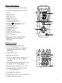
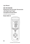
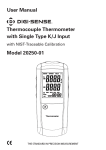
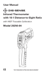
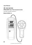
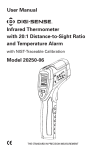
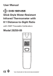
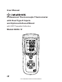
User Manual Professional Thermocouple Thermometer with Dual Type K Inputs and Optional Infrared Wand with NIST-Traceable Calibration Model 20250-17 Enter REC DIF THE STANDARD IN PRECISION MEASUREMENT Introduction The Digi-Sense Professional Thermocouple Thermometer (Model 20250-17) with Dual Type K Inputs and Optional Infrared Wand offers fast response and high accuracy. This heavy-duty meter works with two type K thermocouples and one optional infrared probe*. Advanced features include backlight, Max/Min/Avg readings, data Hold, and automatic power-off. The instrument is fully tested and calibrated to NIST-traceable standards. Careful use of this meter will provide years of reliable service. Unpacking Check individual parts against the list of items below. If anything is missing or damaged, please contact your instrument supplier immediately. 1. Meter 2. Two type K flexible probes 3. Carrying case 4. One 9 V battery 5. User manual 6. NIST-traceable calibration report with data *Optional infrared wand (model 20250-24) must be ordered separately. Key Features • Large backlit display shows any combination of T1, T2, T3, T1–T2, T1–T3, T2–T3; plus Max, Min, and Avg readings • Relative time clock on Max/Min/ Avg provides a time reference for major events • Electronic Offset function allows compensation of thermocouple errors to maximize overall accuracy • User-selectable readout in °C, °F, or Kelvin (K) • 0.1°C / 0.1°F / 0.1 K resolution • Scan function (T1, T2, T2, T1–T2, etc.) • Automatic power-off (sleep) mode to conserve battery life • Accepts a wide variety of thermocouple type K probes 2 1 2 Meter Description 1. Thermocouple type K (T1) input 2. Thermocouple type K (T2) input 3. LCD 13 3 4. Enter button 5. Up button 6. Down button 8 7. Power on/off button 8. Setup / Backlight button REC 11. HOLD button 6 9 9. °C/°F/K button 10. MAX/MIN button 4 Enter 10 5 11 DIF 12. DIF/T1–T2–T3 button 12 13. IR (T3) input* 7 *Optional infrared wand (model 20250-24) must be ordered separately. Display Layout 1. Thermocouple TYPE K icon 1 2. Infrared IR TEMP icon (requires Optional IR wand sku number 20250-24) 2 3. Data HOLD icon 6 7 11 6. Secondary display (Max, Min, Avg, or offset T1, T2, T3 reading) 7. Temperature unit icons (°C, °F, K) 8. Tertiary display (elapsed time or T1, T2, T3 reading) 4 5 4. SETUP mode icon 5. Primary temperature display (T1, T2, T3, T1–T2, T1–T3, or T2–T3 reading) 3 8 9 10 9. Low-battery indicator 10. Elapsed time (hour:min or min:sec) 11. MAX, MIN, AVG icons 3 Setup and Operation 1. Press the Power on/off button to turn unit on. Using Thermocouple Input(s) 1. Plug the type K thermocouples into the T1 and T2 input connectors. 2. After one second the thermometer displays the first readings (T1 on upper display, T2 on secondary display). If no thermocouple is plugged into the selected input or the thermocouple is not properly connected, the display will show "- - - -". If the temperature being measured is outside the unit’s valid range, the display will show “OL” (overload). Using Infrared Input 1. Purchase optional infrared wand (model 20250-24). 2. Plug the IR wand into the T3 (IR) input connector. “T3 - - - -” will show on screen. If the IR wand is not connected, “T3 - - - -” is not shown on the screen. 3. Press the SCAN button on the IR wand to begin measuring. The IR (T3) measurement is shown on the tertiary display. Displaying Temperatures 1. Press °C/°F/K button to select desired temperature unit: Celsius (°C), Fahrenheit (°F), or Kelvin (K). 2. As a default, the T1 temperature reading appears in the primary display, the T2 reading in the secondary display, the T3 reading in the tertiary display. 3. Use the DIF/T1–T2–T3 button to toggle between showing the T1 (type K), T2 (type K), T3 (infrared), T1–T2, T1–T3, T2–T3 (temperature differentials) measurement in the primary, secondary, or tertiary display. Optional IR wand (model 20250-24) 4 Hold Function 1. Press HOLD button to freeze the readings on the display. The screen shows the HOLD icon. 2. Use the DIF/T1–T2–T3 button to toggle between showing the T1 (type K), T2 (type K), T3 (infrared), and T1–T2, T1–T3, T2–T3 (temperature differentials) measurement in the primary, secondary, or tertiary display. 3. Press HOLD button again to turn off the HOLD function and resume measuring. MAX, MIN, and AVG Function 1. Press MAX/MIN button to step through the maximum (MAX), minimum (MIN), and average (AVG) readings. The elapsed time since entering Max/Min/Avg mode, or the time at which the minimum or maximum occurred, appears on the display. 2. Press and hold the MAX/MIN button for three seconds to exit the Max/Min/Avg mode and return to normal operation. Backlight Function Quickly press the Setup/Backlight button to turn the backlight on and off. 5 Setup Options Use the Setup mode to change the temperature offset and sleep mode settings. Note: Setup mode is disabled in Max, Min, and Avg modes. Changing a Setup Option 1. Press and hold Setup/Backlight button for three seconds to enter or exit Setup mode. When the meter is in Setup mode, the display shows the SETUP icon. 2. Press Up or Down button to scroll to the setup option you want to change. 3. Press ENTER button to indicate that you want to change this setting. 4. Press Up or Down button until the setting you want to use appears on the display. 5. Press ENTER button to store the new setting into memory. Offset Function The primary display shows the temperature plus the offset and the secondary display shows the offset. You can store individual offsets for T1, T2, T3. Use the Offset option in the Setup mode to adjust the thermometer’s readings to compensate for the errors of a specific thermocouple and IR temperature. The allowable adjustment range is ±9.0°F or ±5.0°C. 1. Plug the thermocouple into the T1 input connector. 2. Place the thermocouple in a known, stable temperature environment (such as an ice dry well calibrator). 3. Allow the readings to stabilize. 4. While in Setup mode, press the Up or Down button to scroll to the “T1” screen. 5. Press Enter button to access the setting. 6. Use the Up and Down buttons to change the offset value until the primary reading matches the calibration temperature. 7. Press ENTER button to store the new setting into memory. Changing the Auto Power-Off (APO) Mode The meter’s default mode is to automatically shut off after 20 minutes of non-use. To disable the auto power-off mode, enter the Setup mode. 1. While in Setup mode, press Up or Down button to scroll to the “SLP” screen. 2. Press ENTER button to display “On.” 3. Use the Up or Down buttons to toggle between “On” (sleep mode on) or “Off” (sleep mode off). 4. Press ENTER button to store the new setting into memory. 5. Note: Meter defaults back to “On” once meter is powered off. 6 Specifications Range Temperature, external type K thermocouple –328 to 2501°F (–200 to 1372°C) Resolution Temperature display 0.1 (<1000) or 1 (≥1000) Accuracy T1, T2 (T/C) ±[0.15% reading + 1.8°F (1°C)] above –148°F (–100°C) ±[0.5% reading + 3.6°F (2°C)] below –148°F (–100°C) T1–T2 (T/C) ±[0.5% reading + 1.8°F (1°C)] T3 (IR) ±[2.0% reading + 3.6°F (2°C)] T1 (T/C) – T3 (IR) ±[2.0% reading + 5.4°F (3°C)] T2 (T/C) – T3 (IR) ±[2.0% reading + 5.4°F (3°C)] Auto power-off Unit shuts off automatically after 20 minutes to preserve battery life Operating temperature 32 to 122°F (0 to 50°C) Storage temperature 14 to 122°F (–10 to 50°C) Weight 9.8 oz (280 g) Dimensions 8" x 3" x 2" (20.1 x 7.5 x 5 cm) Power One 9 V battery Optional Infrared Wand (Model 20250-24) Temperature range –31 to 1022°F (–35 to 550°C) Resolution 1 mV per °F/°C Basic accuracy ±2% or ±4°F (2°C) Response time Less than 500 ms Optical resolution (Distance-to-Spot ratio) 8:1 Plug diameter Banana plug: 0.16" (4 mm) Dimension 61⁄2 " x 2" x 11⁄2 " (16.4 x 5 x 4 cm) Power One 9 V battery 7 Maintenance, Recalibration, and Repair Cleaning and storage • The meter should be cleaned with a damp cloth and mild detergent when necessary. Do not use solvents or abrasives. • Store the meter in an area within the storage range indicated in the Specifications on page 7. Battery Replacement When the battery power falls low, the low-battery icon will appear on the screen. Replace the 9 V battery in the rear battery compartment by removing the cover. Ensure that the cover is securely refastened when finished. It is recommended that Digi-Sense products are calibrated annually to ensure proper function and accurate measurements; however, your quality system or regulatory body may require more frequent calibrations. To schedule your recalibration, please contact InnoCal, an ISO 17025 calibration laboratory accredited by A2LA. Phone: 1-866-INNOCAL (1-866-466-6225) Fax: 1-847-327-2993 E-mail: [email protected] Web: InnoCalSolutions.com For Product and Ordering Information, Contact: Toll-Free: 1-800-323-4340 Phone: 1-847-549-7600 Fax: 1-847-247-2929 ColeParmer.com/Digi-Sense 1065DGMAN_20250-17 Rev.1 Toll-Free: 1-800-358-5525 Phone: 1-847-327-2000 Fax: 1-847-327-2700 Davis.com/Digi-Sense Manual Part No. 00100-56