1
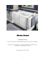
WALK-IN BATH INSTALLATION INSTRUCTIONS AND OWNER’S MANUAL CONGRATULATIONS! You are now the owner of a walk-in bathtub from the most trusted name in plumbing. We thank you for your purchase. Your American Standard ® walk-in bath is a true investment in your health and peace of mind. Customer Support: (866) 423-0800 1 OWNERS MANUAL TABLE OF CONTENTS UNPACKING THE UNIT………………………………………………………………. Page 3 RESPONSIBILITIES OF THE INSTALLER…………………………………………… Page 4 TESTING YOUR TUB BEFORE INSTALLATION…………………………………… Page 5 INSTALLATION PREPARATION…………………………………………………….. Page 6 ELECTRICAL INSTALLATION………………………………………………………. Page 7 INSTALLATION PROCEDURES…………………………… ………………………... Page 8-17 SAFETY INSTRUCTIONS ……………………………… ……………………………. Page 18 OPERATING INSTRUCTIONS…………………………… ………………………….. Page 19-20 CLEANING & MAINTENANCE……………………………………………………..... Page 21 WARRANTY…………………………………………………………………………..... Page 22 TROUBLESHOOTING………………………………………………………………..... Page 23-25 2 OWNERS MANUAL UNPACKING THE UNIT 1. FIRST, inspect the carton for damage: CAREFULLY DOCUMENT AND PHOTOGRAGH ALL PERCEIVED DAMAGE. Report all damage claims to customer service at 1-866-423-0800. 2. DO NOT LIFT THE TUB BY THE PLUMBING. Doing so can result in leaks, for which the installer is responsible. All Walk-In Tubs are water tested before they leave our factory and the bathtub you have purchased has passed inspection. 3. Immediately inspect the unit for damage even if there is no carton damage. All product damage must be reported within 72 hours of receipt from American Standard®. Once the unit is installed, surface damages will be assumed to be installation-related if not reported prior to installation. Installers are also responsible for damage that occurs once the unit is placed in its niche. NOTE: Remove all packaging material except for the protective plastic. This has been placed on the tub at the factory to eliminate abrasions from handling. This should only be removed at final clean up. 4. Inspect the plumbing for any fittings that may have loosened in transit. 5. Read the following instructions completely before installing this product. If the home-owner or installer has any questions, please call us at 1-866-423-0800. 6. You must follow all the instructions in this manual. FAILURE TO READ AND COMPLY WITH ALL INSTRUCTIONS CAN RESULT IN PRODUCT DAMAGE OR INJURY TO BOTH INSTALLER AND HOMEOWNER. IT WILL ALSO RESULT IN ASSUMPTION OF ALL LIABILITY BY SAID INSTALLER. 3 OWNERS MANUAL RESPONSIBILITIES OF THE INSTALLER The Installer must inspect and water test the product prior to installation to ensure the unit is free of defect and /or damage. In the event of a problem, the unit must not be installed. If the packaging or product has been damaged, please call immediately at 1-866-423-0800. This product has been listed by INTERTEK / ETL and IAPMO / C UPC. The product has been tested and complies with the following standards and guidelines: IAPMO /C UPC, UL-1795, ANSI Z-124.1.2, ASME A 112.19.7, ASME A 112.19.15 & CSA B-45. The installer is responsible for compliance to state and local codes. This product is designed to be installed by a licensed tradesperson. Licensed plumbers and electricians should be employed to insure proper installation. Installer assumes all liabilities for installation procedures. Although American Standard® has taken reasonable precautions to ensure that the Quick Drain TM is suitable for residential plumbing; it is the responsibility of the installer to insure that the plumbing is acceptable for use of the Quick Drain TM. American Standard® does not accept responsibility for damage arising from use of the Quick Drain TM. Only accessories authorized by manufacturer should be used with this product. IMPORTANT SAFETY INSTRUCTIONS INSTRUCTIONS PERTAINING TO RISK OF FIRE, ELECTRICAL SHOCK OR INJURY TO PERSONS SAVE THESE INSTRUCTIONS! WARNING! ALL INSTRUCTIONS LISTED IN THIS MANUAL SHOULD BE READ AND FOLLOWED CAREFULLY. ALL PRECAUTIONS PERTAINING TO RISK OF FIRE, ELECTRIC SHOCK, OR INJURY TO PERSONS MUST BE UNDERSTOOD AND EXPLAINED TO OWNER. TO REDUCE THE RISK OF INJURY, CHILDREN OR PERSONS WITH INFIRMITIES MUST NOT BE PERMITTED TO USE THIS PRODUCT WITHOUT CLOSE AND CONTINUOUS SUPERVISION. 4 OWNERS MANUAL TESTING YOUR WALK-IN TUB BEFORE INSTALLATION 1. All American Standard® walk-in baths are 100% water tested at the factory and have passed inspection. Transportation and mishandling may loosen fittings and cause leaks. It is therefore necessary to test the bathtub while there is access to all sides of the bath. 2. The unit needs to be filled with water and inspected for leaks along the door as well as the whirlpool and air systems if equipped. The inspection needs to be performed with and without the whirlpool and / or air systems operating. It is best to test the unit outside by filling with a garden hose. a. Place the tub on a completely flat surface in an area where it may be drained after testing. b. Using a clean rag and warm water wipe down seal to insure it is free of debris. c. Seal the drain hole (this can be done with tape) and fill the tub to at least three inches above the highest jet, or to the bottom of the safety bar if no jets are present. d. Allow the water to stand in tub for 30 minutes and then inspect all plumbing and seals for leaks. e. Using appropriately rated three-prong extension cords, all plugged in to separate outlets, operate all electrical components (air blower, water pump, and heater if applicable) for another 30 minutes and inspect for leaks again. Inspect the unions around the pump and heater. f. If a leak persists at a union after tightening, it may have been over-tightened or might have a displaced O-ring. Disassemble it and make sure the O-ring was seated properly. Do the same if a leak persists at the heater. Verify that the heater threads match the pipe threads. g. Ensure that all jets are open and working, some jets are adjustable for both flow rate and direction of flow. The jet water flow rate is adjusted by turning either the outside ring or the inside nozzle clockwise or counterclockwise. Some jets are not adjustable at the jet face, but can be adjust by the “Leg’s Only Massage”. The “Legs Only Massage” Valve is located near the seat. (If equipped.) . 3. If the pump/blower/lights/heater does not operate: a. Check the breaker to ensure that power is on and make sure that any cables and / or air lines connecting the control boxes to the switches and pumps are firmly attached. Verify the correct electrical circuit and amps of the electrical cord. b. Go to Trouble Shooting Guidelines. (See pages 23-25.) c. Do not run any pumps unless the tub is filled with water to the proper level. Damage due to dry operation of pumps is not covered under the warranty period. (See pg. 22.) Failure to perform these tests before installation will make the installer liable for future repair costs. 5 OWNERS MANUAL INSTALLATION PREPARATION 1. Check the floor area where the tub is to be installed. a. Clean area of any debris or trash. b. Use a 5 or 6-foot level and determine if the floor is level. If the floor is not level, adjust all leveling feet to perfectly level the tub. Note: It is important that all leveling feet are completely touching the floor and level for the door system to work properly. 2. Check to ensure that the drain piping has been “roughed-in” at the proper location. See specification sheets (installation detail) included in this manual. 3. Ensure that the proper electrical service has been installed at the pump location. See electrical Requirements in the manual. (See page 7.) 6 OWNERS MANUAL ELECTRICAL INSTALLATION All electrical wiring must be installed in accordance with the National Electrical Code and with all local codes. All wiring shall be done by a qualified electrician. Run one, two or three branch circuits (as required) from the main electrical service panel to the pump area of the framing structure to provide power to the unit. Electrical components have specific wiring requirements. Refer to the matrix below for the electrical supply requirements for the whirlpool bathtub and factory installed components. Branch circuits must be rated for 110 – 120 volts. Use 12 Gauge, 3 conductor cable for the circuits. If the length run exceeds 100 feet, check with local codes for requirements. Install moisture proof junction box(s) 6” above the floor at the pump end of the framing for each circuit. DO NOT INSTALL THE JUNCTION BOX(S) WHERE IT CAN BE REACHED WHILE SITTING OR STANDING IN THE TUB OR TOUCHING THE FAUCETS. QUICK DRAIN™, LIGHTS, WHIRLPOOL, AIR SPA, COMBO & HEATER ELECTRIAL REQUIREMENTS This section lists the factory installed components of the Whirlpool and/or Air Spa Systems. Note the required number of circuits and their rating for the Whirlpool & Air Spa unit you are planning to install. ELECTRICAL REQUIREMENTS FOR FACTORY INSTALLED COMPONENTS Systems Soaker w / Quick Drain™ Electrical Rating Circuit 1 Electrical Rating Circuit 2 Dedicated Circuit 15 Amp GFCI Soaker w / Light 15 Amp GFCI Soaker w / Quick Drain™ w / Light 15 Amp GFCI Whirlpool or Air Spa 15 Amp GFCI Whirlpool or Air Spa w / Light 15 Amp GFCI Whirlpool or Air Spa w/ Quick Drain™ 15 Amp GFCI 15 Amp GFCI Whirlpool or Air Spa w/ Light & Quick Drain™ 15 Amp GFCI 15 Amp GFCI Whirlpool & Air Spa (Combo) 15 Amp GFCI 15 Amp GFCI Whirlpool & Air Spa (Combo) w/ Light 15 Amp GFCI 15 Amp GFCI Whirlpool & Air Spa (Combo) w/ Quick Drain™ 20 Amp GFCI 15 Amp GFCI Whirlpool & Air Spa (Combo) w/ Light & Quick Drain™ 20 Amp GFCI 15 Amp GFCI 15 Amp GFCI Whirlpool Inline Heater - Dedicated Circuit All electrical connections must be carried out by a certified electrician in accordance with local electrical requirements and codes. 7 OWNERS MANUAL INSTALLATION PROCEDURES ▲ WARNING: When installing whirlpool massage baths, air spa baths, combo baths, or Quick Drain™ equipped baths, the following precautions must be followed: ▲ WARNING: Danger: Risk of electrical shock; connect components to separate circuits, EACH protected by a ground fault circuit interrupter (GFCI) ▲ WARNING: Installation must provide access for servicing the pump and motor (all American Standard® walk-in baths come with access panels for the pump, motor and faucet). 1. Install tub waste/overflow according to instructions included with the provided kits. The Gel Coat Series requires the installation of a door drain with check valve. The check valve and tubing must be installed horizontal to the floor. Some installations will require the purchase of additional fittings. 2. American Standard Faucet Installation # 9FHS-CH Review the installation instructions packed with the faucet set. Mask off the tub’s deck with a protective tape. Locate and mark the center line of the overflow fitting Locate and mark 1 ½” line either side of the tub’s center line to establish the overflow clearance. Follow the drill template and faucet installation instructions. 3. Other Faucet Model and / or Brand Review the installation instructions packed with the faucet set. Mask off the tub’s deck with a protective tape. Locate and mark the center line of the overflow fitting Locate and mark 1 ½” line either side of the tub’s center line to establish the overflow clearance. Verify the first two component mounting clearance on either side of the waste overflow as well as above and below the tub’s deck. Verify the remaining component mounting clearance on both sides of the overflow as well as above and below the tub’s deck. It is recommended the hand held shower be installed on the corner closest to the wall to prevent water from leaking off the deck and on to the floor. 4. Install the optional in-line water heater per manufacturer’s instructions. 5. Standard Walk-In Bath Installation - After framing is complete, set product in place to check fit and make certain that the tub can be properly leveled. (Caution: If the bathtub is not resting on all leveling feet, water will not drain properly and this may cause the door to leak). Secure tub frame to the studs using metal straps. (Not provided.) 5a. Fire-Rated Drywall – If fire-rated drywall is specified, the finished fire-rated wall must be in place before the tub is installed. The dimensions of the framing structure must be increased by the thickness of firerated drywall. 8 OWNERS MANUAL INSTALLATION PROCEDURES WARNING: Never allow the weight of the tub to be supported by wood support stringers and do not use integral tile flange (if equipped) to screw or nail in place, as this will result in product failure and will void the warranty. 6. Verify the product is completely level by checking tub deck surface and ensure all leveling feet are touching the ground. 7. Electrical connection is made by simply plugging each cord into the GFCI outlet. 8. After plumbing and electrical connections have been made, the tub and door seal should be cleaned of dirt and debris. Use warm water and a non abrasive cleaner for clean up. 9. Installation is not complete until the bathtub has been water-tested in place and does not leak. 9 OWNERS MANUAL Alcove Installation ` Faucet and Pump Access Panels IMPORTANT Do not use tile flange to screw or nail tub in place. Integral Flange Non Integral Flange Model 2651.11X 2848.10X 2848.11X 3051.11X 3052.10X A 50 ½” 48” 48” 50 ½” 51 ½” B 26 ¼” 28” 28” 30 ½” 29 ¾” C 37 ½” 38” 37 ½” 37 ½” 42” D 9 ½” 10 ¾” 10” 9 ½” 12 ½” E 11 ½” 14” 14½” 14½” 14½” F 15 ½” 16 ¾” 16” 15 ½” 17” 3151.10X 50 ½” 31 ¼” 3060.10X 59 ½” 29 ¾” 3260.21X 59 ½” 32 37 G N/A N/A N/A N/A N/A 37 ½” 10” 14 ½” 15 ¾” 38” 37 ½” 31 ¼” 14½” 15 ¼” 38” 11 ½” 16” 20½” N/A Tubs installed in an alcove installation require a raised flange to prevent water from seeping past the tub and into the wall. Tubs without a raised flange shall be installed with a tile flange kit such as model: 9FLNG or a similar type. The flange kit is a long plastic strip that is fits onto the rim of the tub to provide the leak protection needed. The tile flange should be installed on the tub before it is placed in the alcove. Install the tile flange along all sides of the tub where the wall will be. Measure to fit and miter cut the flange corners. The flange should be attached to the tub with a silicone adhesive. Drain Overflow Warning: Never attempt to nail or screw thru the tub as this will result in product failure and will void the warranty. 10 OWNERS MANUAL Acrylic Extension Kit Installation The Acrylic Extension Kit is designed to accommodate all acrylic walk-in tubs to fit within a 60” alcove pocket. The top panel measures 30” x 20” (depth x width) and the front panel 37 ½” x 20” (height x width). The panels must be trim to fit the unit within the 60” alcove. Step 1 Temporary locate the tub within the alcove walls. Level the tub along the deck and apron. Measure and record the distance from the tub and apron to the adjacent alcove wall. Steps 2, 3, & 4 Mask off and mark the trim lines for the top and front extension panels. Using a high speed carbide tooth blade, cut along the trim lines Mark a horizontal line that is parallel to the tub’s deck along the back and adjacent wall of the alcove. Mark a vertical line that is parallel to tub’s apron on the adjacent wall of the alcove. Install three wood stringers approximately 3/8” below the horizontal and vertical lines. Verify the fit of the front panel and then the top panel to the alcove opening. Shimming may be required to achieve a level fit. 11 OWNERS MANUAL Acrylic Extension Kit Installation Steps 5 & 6 Remove the tub from the alcove and install the front and then top panel with the self tapping fasteners. Steps 7 & 8 Apply the temporary clamps to help support the front and top panels while re-locating the tub back into the alcove. Remove temporary clamps, check level, shim if necessary, and seal in panels with silicone. 12 OWNERS MANUAL Gelcoat Extension Kit Installation The Gel Coat Extension Kits are designed for each unit to fit within a 60” alcove packet. The top and end panels have integral flange for easy of installation. Step 1 Step 2 Temporary locate the tub within the alcove walls. Level the tub along the deck and apron. Measure the distance from the tub and apron to the alcove wall. Verify the fit of both front and top extension panels. Mark a horizontal line that is parallel to the tub’s deck along the back and adjacent wall of the alcove. Mark a vertical line that is parallel to tub’s apron on the adjacent wall of the alcove. Install three wood stringers approximately 3/8” below the horizontal and vertical lines. 13 OWNERS MANUAL Gelcoat Extension Kit Installation Step 3 Step 4 Remove the tub from the alcove. Install the front and then the top panel with the tub brackets. Apply the temporary clamps to help support the panels while re-locating the tub back into the alcove. Remove temporary clamps, check level, shim if necessary, and seal in panels with silicone. ___ ___ 14 OWNERS MANUAL Drain Overflow Installation Drain / Overflow Information A drain / overflow assembly is provided with the tub must be installed on the bath, water tested and connected to the sanitary system of the house. Some drain / overflow kits are packed with the waste flange, strainer, overflow cover, and fasteners, packed separately within the kit to protect the trim finish. Follow the installation instructions provided with the drain / overflow kit. After the drain is fully installed, test the unit for proper drainage. If the unit does not drain properly, rectify the condition before proceeding with installation. American Standard is not responsible for the removal or re-installation costs. Note: All gel coat models require additional installation of the door drain to the waste overflow. Connection of the Quick Drain Quick Drain System requires the connection to a minimum 1 ½” sanitary drain line. Use UPC Approved PVC Glue, Primer, and Schedule 40 1 ½” pipe. Do not change or modify the location and or piping of the Back Flow Manifold The sanitary tee is installed directly above the drain tee with clearance not greater than 1”. Dry fit the drain overflow assembly to the sanitary drainage pipe and check for proper fit. Glue the Quick Drain Fittings, pipe and drain overflow assembly to the sanitary drainage pipe. NOTE: Water tight installation of the waste / overflow is the installer’s responsibility. Drain leakage is excluded from Safety Tubs warranty of this product. We have taken reasonable precautions to ensure the Quick Drain is suitable for residential plumbing. It is the responsibility of the installer to insure the sanitary system is acceptable for the use of the Quick Drain. We do not accept responsibility for damage arising from the use of the Quick Drain. 15 OWNERS MANUAL Threshold Drain Installation Threshold Drain Information All gel coat walk-in bathtubs are provided with a threshold door drain. All acrylic walk-in bathtubs feature the “Patented T5 Door System” which does not require the threshold drain. Connection of the Door Drain Door Drain requires the connection to a minimum 1 ½” sanitary drain line. Use UPC Approved PVC Glue, Primer, and Schedule 40 1 ½” pipe. The door drain, check valve, and 3/8” vinyl tubing are installed on the walk-in bathtub The door drain coupling has an integral 3/8” barb for connection of the door drain line. The drain coupling must be located between the drain tee and shoe along the tub’s drain line. The 3/8” barb on the drain coupling must be positioned parallel to the sub floor. Connect the door drain assembly and drain coupling with 3/8” vinyl tubing. Verify the coupling barb, check valve, and 3/8” tubing are horizontal to the floor. Glue all components and tubing in place use PVC Glue. 16 OWNERS MANUAL Inline Heater Installation Whirlpool In-Line Heater All whirlpool systems are deigned with an In-Line Heater Blank. The threads and union set on the heater blank and heaters are specifically designed for our system. All other heaters and heater blanks will not interchanges with our system. The heaters are equipped with a preset pressure switch which will not allow the heater to turn on if the pump is not running with water flowing through the whirlpool system. The heater includes an exclusive High Limit Switch. This safety circuit will not false trip from the hot tap water. It will turn off the heater is the thermostat fails. If your whirlpool is equipped with adjustable jets, or other flow control systems, the pre-set pressure switch may not activate the heater. To assure proper heater operation, all jets may need to fully open with the pump operating at or near maximum flow. Installation of the In-Line Heater Verify there is a dedicated 120 volt, 15 Amp Circuit with a GFCI outlet available. Located the Ready Heater Fitting on the walk-in bathtub. Loosen the union nuts and remove the Heater Ready Fitting. Verify the heater and union fitting threads are the same. Placed the ribbed side of the gasket to the union fitting. Insert the heater and slowly hand tighten the union nuts to a smug fit to insure proper alignment. Once the heater alignment is verified, give a ¼ turn to each union nut to insure a good seal. Fill the tub with water and check for water leaks with and without the whirlpool pump running. 17 OWNERS MANUAL IMPORTANT SAFETY INSTRUCTIONS INSTRUCTIONS PERTAINING TO RISK OF FIRE, ELECTRICAL SHOCK OR INJURY TO PERSONS WHEN USING THIS UNIT, BASIC PRECAUTIONS SHOULD ALWAYS BE FOLLOWED. ▲ WARNING: Risk of personal injury. Use this unit for its intended use as described in this manual. DO NOT use attachments not recommended by the manufacturer. ▲ WARNING: Risk of personal injury. To avoid injury, exercise caution when entering or exiting your walk-in bath. ▲ WARNING: Risk of personal injury. To reduce the risk of injury, do not permit children or persons with infirmities to use this product unless they are closely supervised at all times. ▲ WARNING: Risk of hyperthermia and possible drowning. People using medications, herbal remedies, sleep aids, and /or having adverse medical history should consult a physician before using this product. ▲ WARNING: Risk of personal injury. Water temperatures over a 100 F (38 C) may be hazardous to your health. Check and adjust water temperature for your personal comfort. ▲ WARNING: No food or Alcoholic Beverages. Use of your bathtub immediately after meals is not recommended. Avoid alcohol consumption before or during the bathing. Alcoholic beverages can cause drowsiness or hyperthermia resulting in loss of consciousness or even drowning. ▲ WARNING: Pregnancy. If you are or think you may be pregnant, consult your doctor before using the bathtub. ▲ WARNING: Risk of personal injury. Risk of electric shock; do not permit electric appliances (such as a hair dryer, lamp, telephone, radio or television) within four feet of this bathtub. ▲ WARNING: Risk of personal injury. Never drop or insert any objects into any openings. ▲ WARNING: Risk of personal injury. Do not operate this unit without the guard over the suction fittings. The unit must be connected only to a supply circuit that is protected by a ground-fault circuit-interrupter (GFCI). Such a GFCI should be provided by the installer and should be tested on a routine basis. To test the GFCI, push the test button. The GFCI should interrupt power. Push the reset button. Power should be restored. If the GFCI fails to operate in this manner, there may be a ground current flowing, indicating the possibility of an electric shock. Do not use this massage bathtub. Disconnect the whirlpool bathtub and have the problem corrected by a qualified service representative before using. To reduce the risk of electrical shock, the dedicated electrical supply circuit(s) must be grounded. To do this, connect the third leg of the 3-conductor wiring cable to the grounding terminal of the electrical service panel and run continuously to the green grounding screw on the GFCI or electrical receptacle in the wiring compartment. 18 OWNERS MANUAL SAVE THESE INSTRUCTIONS! OPERATING INSTRUCTIONS 1. Enter your American Standard® walk-in bath, close the door, place handle in down position, and fill the bath to at least 2 inches above the highest jet before activating the whirlpool pump (if equipped). Do not apply excessive pressure when placing the handle in the close position. Do not put weight on the door when entering and exiting the tub. It is recommended to leave the door in the open position when the tub is not in use. 2. If your American Standard® walk-in bath is equipped with Whirlpool Jets, Air Spa, or Combo system, the pump or blower is operated by the push button switch labeled “Jets” or “Air”. Both the number of buttons and their assorted functions vary. Do not depress the button(s) repeatedly and/or rapidly as all function(s) are controlled electronically. It may take a few seconds before any change becomes perceptible. Refer to massage instructions sheet for more information on the controls. 3. If your American Standard ® walk-in bath is equipped with whirlpool jets, you can adjust the direction and flow rate of the jets to your liking by moving the nozzle for direction and turning the outside ring or the nozzle clockwise or counterclockwise for the flow rate. Some jets are not adjustable at the jet face, but can be adjusted by the “Legs Only Massage” valve located near the seat. (If equipped.) 4. The Legs Only Massage (whirlpool & combo systems only) opens and closes the jets above the seat which allows you to fill the tub half-way and operate only the lower whirlpool jets. The Legs Only Massage valve must be closed when filling the tub half-way and operating the whirlpool. Failure to close the valve, when filling the tub half-way will result in water shooting out of the jets above the seat when the pump is activated. (If equipped.) 5. If your American Standard® walk-in bath is equipped with an Air Spa system, you can activate the heated blower by pushing the push button on the deck. Push the button to turn on / off and cycle for the various speeds. 6. If your American Standard® walk-in bath is equipped with an in-line heater, the heating element will come on automatically, but only when the whirlpool system is turned on. This heater is designed to extend the comfortable bathing time, but does not reheat the bath water. 7. If your American Standard® walk-in bath is equipped with the Automatic Tub Clean System - Ozone, the system will turn on automatically when the whirlpool system is turned on. 8. If your American Standard® walk-in bath is equipped with the Quick DrainTM, this system has its own dedicated pump, suction and switch to activate the drain. Simply open the traditional drain system (turn the overflow) and then press the Quick Drain™ on/off switch to activate the drain. When the water falls below the suction guard, press the control switch to turn the drain system off. 19 OWNERS MANUAL SAVE THESE INSTRUCTIONS! OPERATING INSTRUCTIONS 9. If your American Standard® walk-in bath is equipped with Chromatherapy lights, the lights have a dedicated control button. Pressing the control button off and back on will change the color of light. 10. If any factory-installed fittings have been removed, do not operate the unit. A safety hazard may have been created by this modification. Seek the help of a qualified professional. 11. DO NOT use bubble bath or Epsom salts when any pumps are operating. Bath oils may be used; however, their use will require more frequent purging and cleaning of the whirlpool and/or air spa systems. 12. Both whirlpool and air spa systems are designed so that water will drain from the plumbing after each use. 13. There are no user-serviceable parts located under the tub. PURGE CYCLE All air blowers are equipped with a purge cycle to remove residual water from the lines. The purge cycle will begin approximately 20 minutes after the unit is initially turned off and will continue for several minutes. Do not be alarmed when the cycle begins. IN-LINE HEATERS If your bathtub is equipped with an optional in-line heater it will operate only when the pump is on. Note: the in-line heater is designed to keep your water warmer longer but is not designed to increase the water temperature. Heat settings are not adjustable. 20 OWNERS MANUAL CLEANING AND MAINTENANCE Pump and pipe circulation systems should be flushed before first use and on a monthly basis when product is under normal use. Below are the recommended procedures for cleaning: Do not run whirlpool dry. Fill the tub with hot water 2-3 inches above the jets and add 2-3 teaspoons of low foaming detergent such as dishwashing machine detergent. Turn on whirlpool system and run for 10 minutes. Drain tub completely. Fill tub with cold water above jets. Turn on whirlpool system and run for 15 minutes. Drain tub completely. Cleaning the “suction cover”: Clean and remove any hair or lint from the suction cover. On a monthly basis, unscrew the suction cover and clean away any hair, lint or debris from the cover and housing, then remount the cover in place. Suction covers with visible screws from inside the tub can be removed. Some suctions are intended not to be removed and have no visible fasteners. This style of suction cover does not need to be removed for cleaning. Never operate the unit with the safety suction cover off. Do not use abrasive cleaners as they will scratch and dull the surface. Use a mild liquid household detergent cleaner such as Clorox Soft Scrub®. Plaster can be removed using a wooden stick. DO NOT USE METAL SCRAPERS, WIRE BRUSHES, WATER BARRIER WALLBOARD OR OTHER HARSH ABRASIVE TOOLS. Usually a mild detergent will remove construction debris. More stubborn debris may be removed with denatured alcohol, or Clorox Soft Scrub® cleaner. Light scratches and dulled areas may be restored to original luster by rubbing with an automotive type cleaning compound such as DuPont White Polishing Compound®. 21 OWNERS MANUAL LIMITED WARRANTY COVERAGE American Standard® Walk-In Baths are warranted in accordance with the following warranty: This warranty is extended to the first purchaser and does not extend to products previously used as display models or products that have been modified or repaired by anyone else but American Standard® unless approved by American Standard®. American Standard premium acrylic walk-in baths come with a fifteen (15) year warranty on the bathtub, ten (10) year warranty on the tub components and a Lifetime Warranty on the door seal. American Standard walk-in baths constructed of hi-gloss gelcoat construction come with a ten (10) year warranty on the bathtub, five (5) year warranty on the tub components and a Lifetime Warranty on the door seal. WARRANTY LIMITATIONS In the event of a defect in the material or workmanship of a product, defective products will be repaired or replaced. The manufacturer shall not be liable for the expense of removing defective products or installing replacement products or the expense of adjoining components such as tile, marble, wall panels, ceilings etc. No liability shall exist for incidental or consequential damages caused in whole or part by any defect in this product. No warranty, expressed or implied, including any warranty of merchantability or fitness for a particular purpose, shall apply after the warranty period described above. This warranty does not cover defects or damage caused by the common carrier or installer from, without limitation, any of the following: careless handling, lifting bathtubs by the piping, modification of the product for any reason, improper installation (including installation not in accordance with instructions provided with the unit), and acts of God. RETURN POLICY American Standard® is committed to providing premium customer service. In the event that a product must be returned due to reasons other than defects, as mentioned in the warranty, the following procedures apply: Requests for returns and/or exchanges must be made within 30 days of receipt of product. The product must be in its original packaging and received at American Standard in saleable condition. All returns will receive a 15% restocking fee plus all freight costs of the original shipment and return shipment to American Standard. All requests for return must first be approved by American Standard and have an assigned Returned Merchandise Authorization (RMA#). 22 OWNERS MANUAL TROUBLE SHOOTING GUIDELINES WHEN SERVICING THIS UNIT, BASIC PRECAUTIONS SHOULD ALWAYS BE FOLLOWED. ▲ To reduce the risk of injury, keep all components in a vented enclosure and out of the reach of ▲ ▲ ▲ ▲ ▲ children. Risk of Electrical Shock – Connect only to a grounding type receptacle protected by a ground fault circuit interrupter (GFCI). Verify all components are installed to dedicated circuit(s) with the recommended electrical rating . All the components are manufactured with 36” pigtail cord and designed to be plugged directly into a ground fault circuit interrupter (GFCI). DO NOT CUT OR SPLICE INTO THE COMPONET(S) 3 FOOT PIGTAIL CORD(S). All components are designed for indoor use on a whirlpool tub. Quick Drain Pump Motor Will Not Start – Check For: Quick Drain Control Button should be illuminated. If not , verify the following a. The pump is plugged into the control box. b. The control box is plugged into the outlet. c. The control button is plugged into the control box. Improper or loose connections, open switches or relays, blown circuit breakers. Manually check rotation of motor shaft for free movement and obstruction. Motors Cuts Out – Check For: Wiring, loose connections etc. Low Voltage at motor. (Frequently caused by undersized wiring.) Binding or overload. (Amperage Reading.) Motor Hums, But Will Not Prime. –Check For: Make sure all suction, discharge lines and valves are open and un-obstructed. Check for correct water level. Block off suction and determine if pumps develops a vacuum. If pump develops a vacuum check discharge line for obstruction or a leak in the suction line. If the pump does not develop a vacuum and the pump has the correct water level, check for proper voltage and / or check the pump wet end for clogging or debris 23 OWNERS MANUAL TROUBLE SHOOTING GUIDELINES Whirlpool Pump Motor Will Not Start – Check For: Check the air line between the motor and air button for connection and depress to test air signal. Improper or loose connections, open switches or relays, blown circuit breakers. Manually check rotation of motor shaft for free movement and obstruction. Motor Cuts Out – Check For: Wiring, loose connections etc. Low Voltage at motor. (Frequently caused by undersized wiring.) Binding or overload. (Amperage Reading.) Motor Hums, But Will Not Prime. –Check For: Make sure all suction, discharge lines and valves are open and un-obstructed. Check for correct water level. Block off suction and determine if pumps develops a vacuum. If pump develops a vacuum check discharge line for obstruction or a leak in the suction line. If the pump does not develop a vacuum and the pump has the correct water level, check for proper voltage and / or check the pump wet end for clogging or debris. Air Massage Motor Will Not Start – Check For: Check the air line between the motor and air button for connection and depress to test air signal. Improper or loose connections, open switches or relays, blown circuit breakers. Manually check rotation of motor shaft for free movement and obstruction. Motor Cuts Out – Check For: Verify if the air supply line from the blower to the manifold is connected and not obstructed. Wiring, loose connections etc. Low Voltage at motor. (Frequently caused by undersized wiring.) Chromatherapy Lights Lights Will Not Operate – Check For: Check the air line between the control box and air button for connection and depress to test air signal. Wiring and /or loose connections etc Improper or loose connections, open switches or relays, blown circuit breakers. 24 OWNERS MANUAL TROUBLE SHOOTING GUIDELINES Heaters All heaters are equipped with a preset pressure switch which will not allow the heater to turn on if the pump is not running with water flowing through the whirlpool system. The heater includes an exclusive High Limit Switch. This safety circuit will not false trip from hot tap water. It will turn off the heater is the thermostat fails. If your whirlpool is equipped with adjustable jets, or other flow control systems, the pre set pressure may not activate the heater. To assure proper heater operation, all jets may need to fully open with the pump operating at or near maximum flow. Heater Will Not Operate – Check For: Improper or loose connections, open switches or relays, blown circuit breakers. Wiring, loose connections etc. Overload. (Amperage Reading.) O-Zone Generators All O-Zone Generators are equipped with a preset vacuum switch which will not turn on if the pump is not running with water flowing through the whirlpool system. The O-Zone Generator includes an exclusive High Limit Switch and will not false trip from tap water. If your whirlpool is equipped with adjustable jets, or other flow control systems, the pre set vacuum may not activate the generator. To assure proper operation, all jets may need to fully open with the pump operating at or near maximum flow. O-Zone Generator Will Not Operate – Check For: Improper or loose connections, open switches or relays, blown circuit breakers. Form # 0610 25