1
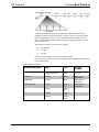
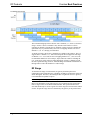
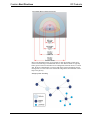
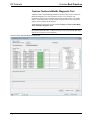
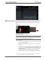
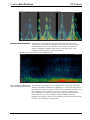
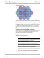
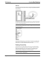
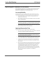
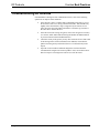
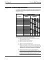
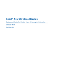
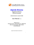
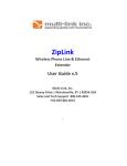
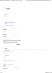
Crestron Best Practices for Installation and Setup of Crestron RF Products Reference Guide The specific patents that cover Crestron products are listed at patents.crestron.com. Crestron, the Crestron logo, Cresnet, Crestron Toolbox, infiNET, and infiNET EX, are either trademarks or registered trademarks of Crestron Electronics, Inc. in the United States and/or other countries. Bluetooth is either a trademark or registered trademark of Bluetooth SIG, Inc. in the United States and/or other countries. iOS is either a trademark or registered trademark of Cisco Systems, Inc. in the United States and/or other countries. Android is either a trademark or registered trademark of Google, Inc. in the United States and/or other countries. Other trademarks, registered trademarks and trade names may be used in this document to refer to either the entities claiming the marks and names or their products. Crestron disclaims any proprietary interest in the marks and names of others. Crestron is not responsible for errors in typography or photography. This document was written by the Technical Publications department at Crestron. ©2014 Crestron Electronics, Inc. Crestron Best Practices RF Products Contents Best Practices for Installation and Setup of Crestron RF Products 1 Introduction ............................................................................................................................... 1 Wireless Characteristics .............................................................................................. 1 RF Channels ................................................................................................................ 3 RF Range ..................................................................................................................... 4 Crestron Toolbox InfiNetEx Diagnostic Tool ............................................................. 6 Installing RF Devices ................................................................................................................ 7 Creating a Network List .............................................................................................. 7 Conducting a Site Survey ............................................................................................ 7 Building a Channel Map ............................................................................................ 12 Installing and Configuring RF Gateways .................................................................. 15 Verifying Connectivity .............................................................................................. 16 Improving Wi-Fi Network Performance .................................................................................. 17 Increasing Reliability................................................................................................. 17 Improving Reconnection Time .................................................................................. 17 Troubleshooting RF Devices ................................................................................................... 18 Further Inquiries ...................................................................................................................... 19 Appendix: Channel Map Worksheet ........................................................................................ 20 Reference Guide – DOC. 6689E Contents • i Crestron Best Practices RF Products Best Practices for Installation and Setup of Crestron RF Products Introduction This document outlines the Crestron® recommended practices for installing and troubleshooting Crestron Radio Frequency (RF) devices. Explanations of Crestron RF protocols and correct installation procedures are provided. Unlike Cresnet® or Ethernet networks that use a physical medium of transmission, ensuring connectivity and eliminating interference in a wireless network is much more difficult. Wireless networks require a significant amount of planning compared to hard-wired networks. Many additional factors affecting the strength and reliability of RF signals must be taken into consideration, including walls, furniture, other electronic equipment, and even people. Many common household electronic devices emit electromagnetic energy, which can severely degrade wireless network performance. It is therefore necessary to use special test equipment to detect the level and locations of interference present in each unique installation. The most common cause of interference problems is a direct result of installing equipment that operates on the same frequency as a cordless phone, baby monitor, or microwave oven. This document helps the user avoid those problems. Wireless Characteristics Wireless signals are transmitted and received using waves in the RF spectrum, which is a portion of the electromagnetic spectrum. The long radio wavelengths allow signals to pass through solid objects such as walls. The limited range of wireless signals in the RF spectrum allows networks in different buildings on the same street to coexist. The following illustration shows the RF spectrum within the electromagnetic spectrum. Reference Guide – DOC. 6689E Best Practices – RF Products • 1 RF Products Crestron Best Practices Electromagnetic Spectrum As shown in the illustration above, the frequencies within the RF spectrum are divided into smaller portions called bands. A band is a range of frequencies that is broad enough to allow for one or more communication paths without affecting adjacent bands. Only particular transmission bands are permitted without a special license from the FCC. Three bands are used by Crestron wireless products: • 418-433 MHz • 2.4 GHz • 5.8 GHz Crestron wireless products do not use the 900 MHz band. Crestron wireless network types, associated bands, and related information are listed in the following table. Crestron RF Network Table WIRELESS NETWORK BAND TYPE DEFAULT CHANNEL Wi-Fi (IEEE 802.11a/b/g/n) 2.4 GHz (802.11b/g/n) 5.8 GHz (802.11a/n) Point to point IEEE 802.11 Channel 1 infiNET™ 2.4 GHz Mesh IEEE 802.15.4 Channel 26 infiNET EX 2.4 GHz Mesh IEEE 802.15.4 Channel 15 Extended Range 2.4 GHz Point to point IEEE 802.15.4 Channel 20 — 2.4 GHz Point to point — — 433 MHz Point to point — — 418 MHz Point to point — ® 2 • Best Practices – RF Products Reference Guide – DOC. 6689E Crestron Best Practices RF Products Devices using the same RF band can interfere with one another’s communication. As shown in the table on page 2, most of the current Crestron product offerings transmit using the 2.4 GHz wireless communication band. Even though products on different wireless networks cannot communicate with each other, they can create interference that degrades performance or eliminates connectivity. Most wireless networks use the 2.4 GHz band, and consequently most connectivity issues are concentrated in that band. The 2.4 GHz band is therefore the focus of this document. RF Channels Each RF network type divides the communication band into separate communication channels. Crestron 2.4 GHz products use two different methods to divide the band: 1. infiNET™, infiNET EX®, and Extended Range use 802.15.4 channel mapping, which provides 16 channels numbered 11–26. Each channel is non-overlapping, which ensures that a device communicating on one channel cannot affect devices communicating on any other channels. NOTE: When 802.15.4 channels are referred to in this document, the reference relates to infiNET, infiNET EX, and Extended Range technologies. 2. 802.11b and 802.11g and 802.11n use the same Wi-Fi channel map. Eleven channels, numbered 1–11, can be used in the U.S., and more channels can be used in other countries. Each channel overlaps three channels on each side; for example, a device communicating on channel 6 causes interference to any devices communicating on channels 3, 4, 5, 7, 8, and 9. As a result, in this example, there are only three available non-overlapping Wi-Fi channels: 1, 6, and 11. NOTE: 802.11a uses the 5.8 GHz band and has a different RF channel mapping than that of 802.11b, 802.11g, and 802.11n. While 802.11a does not have a line-of-sight transmission distance as good as that of 802.11g or 802.11n, 802.11a often has much less interference. In a poor RF environment, 802.11a can provide a more robust solution than 802.11g or 802.11n. The following illustration shows the division of the 2.4 GHz band as it relates to 802.15.4 and 802.11 channels. Reference Guide – DOC. 6689E Best Practices – RF Products • 3 RF Products Crestron Best Practices 2.4 GHz Wireless Network The recommended group of three discrete 802.11 channels (1, 6, and 11) is shown in orange. An 802.11 device on channel 1 may interfere with an 802.15.4 device operating on channel 13 because the two channels overlap. The devices should still operate but may see potential latency due to the overlapping channels. The use of channels 1, 6, or 11 is strongly recommended. As stated previously, not all 802.11 channels are available in all countries. The U.S. supports 802.11 channels 1–11, while most European nations support the full range of channels: 1–13. As a result, the non-overlapping channels of 1, 7, and 13 are the recommended channels for use in Europe, Japan, and most countries excluding the U.S., as shown in yellow in the preceding illustration. All 802.11 channels provide the same operational range; however, Extended Range and infiNET EX channels on the high and low end of the band have a reduced range. RF Range To maximize the range of each network, the gateway should be placed in a centralized location within the home or building. In addition, obstructions reflect and absorb RF signals. Therefore, maximizing the line of sight from devices to gateway is recommended for optimal reception. NOTE: Ranges are not guaranteed as every installation scenario is different. Refer to the illustration on the following page for a comparison of the approximate relative ranges of the several RF networks available. The representation is not to scale and should only be used as a guide for relative ranges between networks within a home. All specific range values are identified by the gateway or the product itself. 4 • Best Practices – RF Products Reference Guide – DOC. 6689E Crestron Best Practices RF Products Approximate Range of Each Network Type Refer to the illustration below for an example of mesh networking, which can be used to extend the range of infiNET EX devices. Note that leaf nodes are typically battery powered devices and cannot act as routing nodes between devices. If a node fails, the device automatically re-routes its path to the gateway through the closest routing node, not a leaf node. Also note that the image shows the maximum of three hops to the gateway. Example of Mesh Networking Reference Guide – DOC. 6689E Best Practices – RF Products • 5 RF Products Crestron Best Practices Crestron Toolbox InfiNetEx Diagnostic Tool A helpful resource when installing infiNET EX devices is the Crestron Toolbox™ InfiNetEx Diagnostic Tool. This tool allows users to view, configure, and troubleshoot all devices on an infiNET EX network. In addition, users can acquire devices, set the network ID, view the amount of hops the device takes and its link quality, and even change the RF channel. Additional help for using this tool can be found in Help | Crestron Toolbox Help | Tools | InfiNetEx Diagnostic Tool. NOTE: Five hops from device to gateway in the infiNET EX network protocol is the maximum allowable limit. For the best results, Crestron recommends three hops from device to gateway in any installation. Crestron Toolbox “InfiNetEx Diagnostic Tool” Screen 6 • Best Practices – RF Products Reference Guide – DOC. 6689E Crestron Best Practices RF Products Installing RF Devices When installing RF devices, it is recommended that the following steps be performed in the order listed below: 1. Create a network list. 2. Conduct a site survey. 3. Build a channel map. 4. Install and configure RF gateways. 5. Verify connectivity. Creating a Network List It is important to know which wireless networks are to be installed. To do so, separate all the wireless devices to be installed into individual networks based on the following guidelines: 1. Do not install more than 30 infiNET devices on a single MNET gateway (infiNET network) or more than 100 infiNET EX devices on a single RF gateway (infiNET EX network). NOTE: Although 100 infiNET EX devices are allowed on a single network, Crestron recommends installing a maximum of 50 infiNET EX devices on a single network to ensure optimal range and operation. 2. To reduce the distances between gateways and devices, group the devices based on their location rather than on their function. For example, instead of creating separate lighting and HVAC infiNET or infiNET EX networks, mix and match devices based on their location. 3. Place 802.11b devices and 802.11g/n devices on different networks. 4. When installing mesh networks such as infiNET and infiNET EX, remember that battery-operated devices do not act as extenders and therefore do not extend the network coverage. 5. To account for unexpected interference, do not exceed 75 % of the typical indoor network range between devices or between a device and a gateway. One gateway is required for each individual network in the installation. The channel of each network is dictated by the gateway; therefore, all client devices communicate on the same channel as the gateway. Keep in mind that some networks have the option of using either 2.4 or 5.8 GHz bands (802.11n). Those networks should be treated separately from networks that must use a 2.4 GHz band (802.11b/g). Once the list of networks is obtained, a site survey can be conducted. Conducting a Site Survey A wireless site survey consists of detecting the level and distribution of outside interference. A site survey often provides early detection of any issues that might be encountered in the installation and, to a large extent, dictates which wireless channels can be used in the installation. The goal of a site survey is to discover the worst-case interference scenario. Reference Guide – DOC. 6689E Best Practices – RF Products • 7 RF Products Crestron Best Practices Site Survey Tools The following tools (provided by others) are recommended for performing a site survey: Wi-Spy, Chanalyzer, and InSSIDer • Wi-Spy, Chanalyzer, and InSSIDer (http://www.metageek.net) • Wi-Fi Analyzer (Android™ OS phone app) • WiPry (iOS® phone app) Wi-Spy is an RF spectrum analyzer built into a small USB dongle that plugs into a PC. It detects the amount of interference across the 2.4 and 5.8 GHz band. Four versions are available: Wi-Spy2.4x and Wi-Spy 2.4x Pro are for the 2.4 GHz band. The 2.4x Pro version provides better signal resolution for improved detection, finds unknown devices, and creates reports based upon its findings. Wi-Spy DBX and DBX Pro monitor the 2.4 and 5.8 GHz band; the pro version provides the same enhanced features as the 2.4x Pro device. Wi-Spy* Wi-Spy 2.4x* Wi-Spy devices use the Chanalyzer or InSSIDer software to report RF signals. The software can detect other wireless networks as well as 2.4 GHz cordless phones, baby monitors, and microwaves. NOTE: Due to the large amount of interference that can come from 2.4 GHz cordless phones, baby monitors, and microwaves, it is recommended that a Wi-Spy device be used to perform wireless site surveys. Wi-Fi Analyzer Wi-Fi Analyzer is an Android OS app capable of analyzing local Wi-Fi networks for a complete channel diagnosis. Refer to the image on the following page for an example. * 8 • Best Practices – RF Products Image source: www.metageek.net Reference Guide – DOC. 6689E Crestron Best Practices RF Products “Wi-Fi Analyzer” Screen1 WiPry WiPry is an iOS phone app capable of analyzing the 2.4 GHz spectrum and acting as a power meter for the 100 MHz – 2.7 GHz spectrum. A required plug-on meter (which is available from www.oscium.com) is needed to fully access the analyze tool. WiPry iOS App2 Site Survey Tasks NOTE: Wi-Spy 2.4x is used as the site survey tool for the examples in this section. A site survey on the 2.4 GHz band is demonstrated because it contains the majority of products communicating over RF. If a tool supports 5.8 GHz, it can perform the same site survey tasks as performed on the 2.4 GHz band. Perform a site survey: 1. Shut down all Crestron RF devices to prevent them from being detected and interpreted as outside interference. 2. Place the detecting equipment in a location where the wireless equipment is to be used. 3. Take a reading that is at least 5 minutes long to capture enough data. During the reading, turn on all electrical equipment in the vicinity, including TVs, computers, Bluetooth® devices, and any microwave ovens (make sure to put something in the microwave oven first). Also, if there are cordless phones present, call the lines and pick up the phones to activate them. Most cordless interference is seen on the 1.9 GHz band and is created when the 1. Image source: https://play.google.com/store/apps/details?id=com.farproc.Wi-Fi.analyzer&hl=en 2. Image source: https://itunes.apple.com/us/app/wipry/id442143525?mt=8 Reference Guide – DOC. 6689E Best Practices – RF Products • 9 RF Products Crestron Best Practices phones ring and the lines are active; there may also be interference on the 2.4 GHz. NOTE: As long as Bluetooth does not consist of the majority of RF devices in the system, any Bluetooth device kept beyond a meter from any access point does not pose much interference in the 802.15.4 network. 4. If the wireless equipment is to be used in a room greater than 1,000 square feet, repeat steps 2 and 3 in various locations within the room. 5. If the wireless equipment is to be used in multiple rooms, repeat steps 1 through 4 in each room. When the reading is complete, Chanalyzer shows the results in a clean and easy-to-read view of the signal over the entire 2.4 GHz band as shown in the following example. Sample Chanalyzer Capture of Total RF Interference In the graph above, the range of wireless signals is roughly -110 dBm up to -20 dBm (-20 dBm indicates a very strong signal). NOTE A good rule to follow is that if almost the entire signal is below -80 dBm, the channel is good. Wi-Fi channels 1, 6, and 11 are highlighted in the sample site survey above. The sample shows that Wi-Fi networks are operating on channel 1 and channel 11, and that the channel 11 network is farther away. By visual inspection of the graph, note that channel 6 is the most free, followed by channel 11. Wi-Fi channel 1 has some minor signals above -80 dBm, which may be fine, but may cause reliability issues for any Wi-Fi devices using that channel or any 802.15.4 devices using channels 11–14. The following sections provide examples of various types of interference. Cordless Phone Interference The following is an example of 2.4 GHz cordless phone interference. There are very high peaks of interference at levels of -40 dBm and above. This level of interference affects all three non-overlapping Wi-Fi channels significantly and causes interference issues with any equipment installed in the 2.4 GHz range. In this scenario, the offending device should be removed or should be replaced with a comparable device that operates in a different band (900 MHz or 5.8 GHz) to provide a reliable installation. Wireless performance in the 2.4 GHz range cannot be guaranteed with outside devices that create such a large amount of interference. 10 • Best Practices – RF Products Reference Guide – DOC. 6689E Crestron Best Practices RF Products Chanalyzer Capture of a Poor RF Environment Created by Cordless Phones Microwave Oven Interference The following is an example of interference emitted from a microwave oven. A microwave oven does not have the high peaks of interference that the 2.4 GHz cordless phone has; however, the radiation of a microwave oven affects most channels. Although the radiation usually does not cause major issues, it can periodically reduce performance and cause instability. Chanalyzer Capture of a Microwave Oven’s RF Interference 802.11g Network Interference The following is an example of a very strong Wi-Fi 802.11g network operating on channel 6 (the channel 6 boundaries are highlighted). A network this strong causes a great amount of interference with any Crestron devices operating in the channel or in the overlapping 802.15.4 channels (16–19). As a result, 802.11 channel 6 and 802.15.4 channels 16–19 must be avoided when selecting operating channels for Crestron gateways. The level of interference drops off sharply outside the highlighted area; therefore, devices can be installed in the same environment as long as they use other channels for communication. Reference Guide – DOC. 6689E Best Practices – RF Products • 11 RF Products Crestron Best Practices Chanalyzer Capture of an 802.11g Wi-Fi Network Building a Channel Map After completion of a site survey, the next step is to build a channel map by selecting the channels for the networks. Use the following channel map worksheet to select the most appropriate channels for the networks. NOTE: For convenience, the channel map worksheet is repeated in the appendix on page 20. A checklist of the steps required to complete the worksheet is also provided. Channel Map Worksheet CHANNEL NUMBERS NETWORK 802.15.4 CHANNELS 11 Wi-Fi 802.11 CHANNELS 1 12 2 13 3 14 4 15 16 5 6 17 7 18 8 19 9 20 21 10 11 22 23 24 25 26 12 • Best Practices – RF Products Reference Guide – DOC. 6689E Crestron Best Practices RF Products Entering a network into the NETWORK column of the channel map worksheet reserves the associated channel for that device and ensures that two devices are not accidentally communicating on the same channel. Note the large size of Wi-Fi 802.11 networks compared to 802.15.4 networks. The Wi-Fi network occupies four rows in the network list. To build a channel map, refer to “Channel Map Guidelines” below. Channel Map Guidelines Enter wireless networks into the channel map as follows: 1. Eliminate the channels that were found to have too much interference during the site survey. 2. Enter the 802.11b/g-only networks. 3. Enter the 802.11a/b/g/n networks. 4. Enter the Extended Range networks. 5. Enter the infiNET networks. Note that in most systems the infiNET network should be set in Fixed mode to remain on the selected channel. For smaller systems with only one or two infiNET gateways and minimal interference detected in the system sweep, it is recommended that the gateway be set to select the operating channel automatically. 6. Enter the infiNET EX networks. Note that infiNET EX networks are always in Fixed mode and default to channel 15 first. NOTE: If there is not enough free space to enter all networks on the channel map worksheet using the steps above, select 802.11a channels for some or all 802.11a/b/g/n networks, and then repeat steps 4–6. The following example of a channel map is based on the sample site survey on page 10. Channel Map Example CHANNEL NUMBERS NETWORK 802.15.4 CHANNELS Eliminated due to interference MLX-3 TPMC-8X-GA TST-600 Personal Computer Lighting Reference Guide – DOC. 6689E 11 12 13 14 15 16 17 18 19 20 21 22 23 24 25 26 Wi-Fi 802.11 CHANNELS 1 2 3 4 5 6 7 8 9 10 11 Best Practices – RF Products • 13 RF Products Crestron Best Practices In the channel map example, wireless networks, shown in italics on the channel map worksheet, are entered as follows: 1. Too much interference exists on Wi-Fi channel 1 and on 802.15.4 channels 11–14; therefore, those channels are eliminated. 2. Wi-Fi channel 6 is the channel that is most free from interference; therefore, a TPMC-8X-GA network uses that channel. 802.15.4 channels 16–19 are then unavailable to any other devices. 3. Channel 11 is the only free Wi-Fi channel remaining for a personal computer Wi-Fi network. 802.15.4 channels 21–24 are then unavailable to any other devices. 4. There are no more free Wi-Fi channels remaining for devices that communicate in the 802.11 network; therefore, 802.11a (5.8 GHz) channels are selected for any remaining Wi-Fi devices. 5. 802.15.4 channel 20 is free; therefore, the TST-600 network is set to that channel. 6. 802.15.4 channel 15 is free; therefore, the MLX-3 network is set to that channel. 7. 802.15.4 channels 25 and 26 are free; therefore, the Lighting network is set to channel 26. Channel 26 is the channel most removed from Wi-Fi networks and therefore should be the least susceptible to interference from Wi-Fi networks. Channel 26, however, also has the shortest range in most Crestron products and therefore may be less reliable than other channels. Careful examination of the site survey is necessary to determine the most appropriate channel assignment. As a result of careful testing and planning, each network is positioned so that it does not interfere with the other networks or receive large amounts of outside interference. Large RF Network Installations If a large number of RF networks are being installed in a single installation, it may not be possible to give each network its own channel. In large environments, networks can be placed on the same channels as long as devices are far enough apart to ensure that the RF signals do not overlap for similar channels. The following illustration shows how Wi-Fi 802.11b/g networks can be spaced by channel so that they do not interfere with each other (as viewed from overhead). 14 • Best Practices – RF Products Reference Guide – DOC. 6689E Crestron Best Practices RF Products Wi-Fi Channel Allocation Map By physically separating the networks, the amount of interference among networks on the same channel is reduced. A standard channel map cannot be created for these installations because multiple networks reside on each channel. Channels 1, 6, and 11 are usually chosen for Wi-Fi networks because they are the only three non-overlapping Wi-Fi channels. 802.15.4 channels 15, 20, 25, and 26 do not overlap with Wi-Fi channels 1, 6, and 11; therefore, channels 15, 20, 25, and 26 can be used on 802.15.4 networks in conjunction with this scheme. For this scheme to function well, however, there must be low interference across the entire 2.4 GHz band. Installing and Configuring RF Gateways The physical location of the RF gateway in relation to the connected wireless devices must be considered for successful installation. When installing an RF gateway, adhere to the following guidelines for optimum performance. Location Place the gateway in a location as follows: • On the same floor as the wireless devices NOTE: For Wi-Fi networks, there should be no more than one wall between the gateway and wireless devices. Both the thickness and material in the obstruction determines how much signal can pass. • Above the height of most furniture • Away from large metal objects (such as an AV rack and televisions) NOTE: Plasma technology also produces RF interference. • At least 12 feet from all other gateways on adjacent channels NOTE: 802.11 channels can be adjacent to 802.15.4 channels as shown in the channel map worksheet on page 12. Reference Guide – DOC. 6689E • At least 3 feet apart for 802.15.4 gateways on non-adjacent channels • At least 6 feet apart for 802.11 gateways on non-adjacent channels Best Practices – RF Products • 15 RF Products Crestron Best Practices Antenna Set the antenna vertically as shown in either of the following illustrations (applicable to most applications). The wireless network is stronger in a perpendicular direction from the antenna. Vertical Orientation If the gateway is positioned parallel to a metal surface (for example, when mounted to a metal wall), orient the antenna horizontally (perpendicular to the metal surface) as shown in the following illustration. NOTE: Positioning the gateway near a metal surface does not provide optimal results and should be avoided whenever possible. In addition, the gateway should not be placed on the ground. Horizontal Orientation Channel After installing the RF gateways, set the channel on each gateway according to the channel map. For Crestron and third-party gateways, refer to the manual supplied with the gateway to find the channel map and specified ranges. Verifying Connectivity After the gateways are installed and the wireless devices are associated with the gateways, move each mobile wireless device (for example, a touch screen) to the extent of the intended usage area to verify connectivity to the gateway. If the connection fails in the usage area, move the gateway to a different location. If necessary, install a second gateway to cover part of the area. NOTE: Crestron products do not support roaming between access points. The devices are restricted to a single gateway. 16 • Best Practices – RF Products Reference Guide – DOC. 6689E Crestron Best Practices RF Products Improving Wi-Fi Network Performance Extra communication parameters can be configured on Wi-Fi networks to improve the performance of the network. If a Crestron access point is being used, those parameters are configured for the network using the wizard. Increasing Reliability The following are some tips beyond the channel selection discussed in previous sections that can help improve the reliability of touch screens on a Wi-Fi network: • Do not hide the SSID (service set identifier). Hiding the SSID can be troublesome for touch screens. • WPA and WPA2 authentication can be problematic; therefore, using WEP may be a useful alternative. NOTE: Using WEP or disabling security can be risky in certain environments. If using WEP, it is recommended that MAC address filtering also be used. Disable security only if the site is safe from security threats. • Do not attempt a roaming configuration with a touch screen as they do not perform the hand-off between access points well. Improving Reconnection Time Several parameters can be set to improve Wi-Fi reconnection time: • For a secure network without reconnect delays, use an open key static WEP encryption in combination with MAC address filtering. NOTE: Encryption provides a more secure network but it can also increase the reconnection time. WEP shared authentication and WPA and WPA2 increase the reconnect time for touch screens. Reference Guide – DOC. 6689E • Use a static IP address on the touch screen so that it does not have to wait to receive a DHCP address before communicating with the control system. • Configure only one access point in each touch screen. By doing this, the touch screen only scans for one network and does not attempt to look for other networks. • Since the wireless radio does not shut down until the power down timeout is reached, performance can be improved and battery life can be maintained by setting the standby and power down timeouts for the customer. It is recommended that the standby timeout be set to a minimum time (1–2 minutes) to turn off the screen backlight but keep the Wi-Fi radio running and connected to the system. The power down timeout can then be set to a longer time based on the user’s preference (15–30 minutes is recommended). Best Practices – RF Products • 17 RF Products Crestron Best Practices Troubleshooting RF Devices If an installation is having wireless communication issues, some of the following quick fixes can help in certain situations: 18 • Best Practices – RF Products • If the network is 802.11a capable and is transmitting using 802.11g, move the network to 802.11a to escape potential interference. Note that this may slightly reduce the network’s range. If supported by the wireless access point, then place the same SSID on both 802.11a and 802.11g networks at the same time to saturate the area. • If the Wi-Fi network is using encryption, remove the encryption. If security is a concern, enable MAC address filtering and disable the SSID broadcast to prevent connection from unauthorized users. • Check the vicinity of the gateway for any other electronic devices that could be interfering with its wireless transmission. In addition, ensure that the path between the gateway and wireless device is not obstructed by metal objects. • Open the Crestron Toolbox InfiNetEx Diagnostics Tool and check the communication strength of all wireless products. Also, ensure that no more than five hops are occurring between devices to reach the router. Reference Guide – DOC. 6689E Crestron Best Practices RF Products Further Inquiries To locate specific information or resolve questions after reviewing this guide, contact Crestron's True Blue Support at 1-888-CRESTRON [1-888-273-7876] or, for assistance within a particular geographic region, refer to the listing of Crestron worldwide offices at www.crestron.com/offices. To post a question about Crestron products, log onto Crestron’s Online Help at www.crestron.com/onlinehelp. First-time users must establish a user account to fully benefit from all available features. Reference Guide – DOC. 6689E Best Practices – RF Products • 19 RF Products Crestron Best Practices Appendix: Channel Map Worksheet For convenience, this appendix provides a blank channel map worksheet followed by a checklist of the steps necessary to complete the channel map. If a site survey is being conducted, it is suggested that this page be printed and included with the items taken to the site location. Channel Map Worksheet CHANNEL NUMBERS NETWORK 802.15.4 CHANNELS 11 Wi-Fi 802.11 CHANNELS 1 12 2 13 3 14 4 15 16 5 6 17 7 18 8 19 9 20 21 10 11 22 23 24 25 26 Complete the channel map according to the following checklist. Step 1: Eliminate the channels that were found to have too much interference during the site survey. Step 2: Enter the 802.11b/g-only networks. Step 3: Enter the 802.11a/b/g/n networks. Step 4: Enter the Extended Range networks. Step 5: Enter the infiNET networks. Note that, in most systems, the infiNET network should be set in Fixed mode to remain on the selected channel. For smaller systems with only one or two infiNET gateways and minimal interference detected in the system sweep, it is recommended that the gateway be set to select the operating channel automatically. Step 6: Enter the infiNET EX networks. Note that infiNET EX networks are always in Fixed mode and default to channel 15 first. NOTE: If there is not enough free space to enter all networks on the channel map worksheet using the steps above, select 802.11a channels for some or all 802.11a/b/g/n networks, and then repeat steps 4–6. 20 • Best Practices – RF Products Reference Guide – DOC. 6689E Crestron Best Practices RF Products This page is intentionally left blank. Reference Guide – DOC. 6689E Best Practices – RF Products • 21 Crestron Electronics, Inc. 15 Volvo Drive Rockleigh, NJ 07647 Tel: 888.CRESTRON Fax: 201.767.7576 www.crestron.com Reference Guide – DOC. 6689E (2021003) 05.14 Specifications subject to change without notice.