1
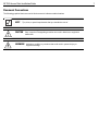
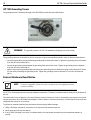
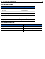
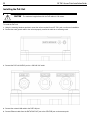
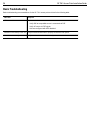
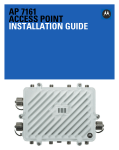
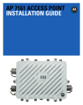
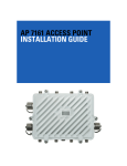
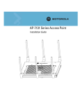
AP 7161
ACCESS POINT
INSTALLATION GUIDE
2
AP 7161 Access Point Installation Guide
AP 7161 Access Point Installation Guide
3
Motorola Solutions reserves the right to make changes to any product to improve reliability, function, or design.
Motorola Solutions does not assume any product liability arising out of, or in connection with, the application or use of any
product, circuit, or application described herein.
No license is granted, either expressly or by implication, estoppel, or otherwise under any patent right or patent, covering or
relating to any combination, system, apparatus, machine, material, method, or process in which Motorola Solutions products
might be used. An implied license exists only for equipment, circuits, and subsystems contained in Motorola Solutions products.
Service Information
If you have a problem using the equipment, contact your facility’s Technical or Systems Support. If there is a problem with the
equipment, they will contact Motorola Solutions Support at: http://supportcentral.motorola.com.
4
AP 7161 Access Point Installation Guide
Introduction............................................................................................................................................ 6
Document Conventions........................................................................................................................ 8
AP 7161 Hardware................................................................................................................................. 8
AP 7161 Antennas............................................................................................................................... 8
Hardware Accessories......................................................................................................................... 9
PoE Accessories................................................................................................................................ 9
Mounting Hardware Accessories........................................................................................................ 9
Package Contents................................................................................................................................ 10
Hardware Installation Guidelines......................................................................................................... 10
Precautions.......................................................................................................................................... 10
Warnings.............................................................................................................................................. 11
Access Point Placement...................................................................................................................... 12
Grounding Requirements................................................................................................................... 12
Ethernet and Lightning Protection...................................................................................................... 12
AP 7161 Hardware Installation............................................................................................................. 13
AP 7161 Ports and Connections........................................................................................................... 13
AP 7161 Antenna Connectors............................................................................................................ 13
AP 7161 Antenna Options................................................................................................................ 14
AP 7161 Console, GE1/POE and GE2 Ports..................................................................................... 15
AP 7161 Grounding Screw................................................................................................................. 16
External Hardware Reset Button........................................................................................................ 16
LED Indicators..................................................................................................................................... 17
Three Radio LEDs.............................................................................................................................. 18
Dual Radio LEDs................................................................................................................................ 19
Installing an AP 7161......................................................................................................................... 20
Required Tools................................................................................................................................. 20
Mounting Bracket Options................................................................................................................ 20
Extension Arm.................................................................................................................................. 21
Pole Mounted Installations................................................................................................................. 22
Vertical Pole Mount............................................................................................................................ 23
Wall Mounted Installations................................................................................................................. 26
Installing the Power Over Ethernet (PoE) Unit..................................................................................... 28
AP 7161 PoE Option.......................................................................................................................... 28
PoE Unit Specifications...................................................................................................................... 29
PoE Interface Connections................................................................................................................ 29
Installing the PoE Unit........................................................................................................................ 30
Other AP 7161 Power Options........................................................................................................... 31
Basic AP 7161 Configuration............................................................................................................... 32
Antenna Type Configuration.............................................................................................................. 32
Automatic Channel Select Override................................................................................................... 32
Specifications....................................................................................................................................... 33
Basic Troubleshooting......................................................................................................................... 36
Regulatory Compliance........................................................................................................................ 37
Wireless Country Approvals............................................................................................................... 37
Health and Safety Recommendations................................................................................................ 37
AP 7161 Access Point Installation Guide
5
Warnings for the Use of Wireless Devices...................................................................................... 37
Potentially Hazardous Atmospheres............................................................................................... 37
Safety in Hospitals.......................................................................................................................... 37
RF Exposure Guidelines.................................................................................................................... 38
Safety Information............................................................................................................................ 38
Reduce RF Exposure - Use Properly............................................................................................... 38
Remote and Standalone Antenna Configurations............................................................................ 38
Power Supply..................................................................................................................................... 38
Wireless Devices - Countries............................................................................................................. 38
Country Selection............................................................................................................................. 38
Operation in the US.......................................................................................................................... 38
Radio Frequency Interference Requirements - FCC.......................................................................... 38
Radio Transmitters (Part 15)............................................................................................................ 38
Radio Frequency Interference Requirements - Canada................................................................... 39
Radio Transmitters........................................................................................................................... 39
CE Marking and European Economic Area (EEA)............................................................................. 39
Statement of Compliance................................................................................................................. 39
Other Countries................................................................................................................................ 40
Waste Electrical and Electronic WEEE................................................................................................. 42
Motorola Solutions Support Center...................................................................................................... 44
AP 7161 Series ROHS Compliance..................................................................................................... 45
6
AP 7161 Access Point Installation Guide
Introduction
Perfect for extending network coverage to outside areas, the AP 7161 brings the latest 802.11n 3x3 Multiple Input Multiple
Output (MIMO) tri-radio design together with rugged outdoor performance. True perimeter security is provided using either a
dedicated dual band sensor or software mode for both 2.4GHz and 5GHz bands to deliver 24x7 rogue detection and termination.
The AP 7161 is optimized with WiNG 5 intelligence, extending QoS, security, and mobility services to the access point to support
better capacity and performance. The AP 7161 is ideal for industrial, enterprise campus, video surveillance, public safety, and
smartgrid utility deployments to extend to the outdoors.
Deployments can be managed using the Motorola WiNG 5 architecture. The Motorola WiNG 5 architecture is a solution
designed for 802.11n networking. It leverages the best aspects of independent and dependent architectures to create a smart
network that meets the connectivity, quality, and security needs of each user and their applications based on the availability of
network resources including wired networks. WiNG 5 is a Third Generation WLAN solution which incorporates the best of both
the first generation Autonomous Access Point WLAN and the second generation Centralized Controller Based WLAN.
The control plane is now distributed between the access points and the controllers. The network administrator has the flexibility
of directing the data plane either being forwarded directly from the access points, or via the controllers. By distributing
intelligence and control between the wireless controllers and APs, the WiNG 5 network can route directly via the best path, as
determined by factors including the user, the location, the application, and the available wireless and wired resources.
Once adopted by a Motorola Solutions RFS4000, RFS6000 or RFS7000 series controller, the AP 7161 is managed as an
Adaptive AP running the WiNG 5 network management protocol. Motorola Solutions WiNG 5 Networks extend the differentiation
that Adaptive APs offered to the next level by now having the services and security available at every point in the network. The
traffic flow is optimized to prevent wired congestion as well as wireless congestion. Traffic flows dynamically, based on user and
application, and finds alternate routes to work around any possible network choke points. Mixed-media application optimization
is the hallmark of WiNG 5 networks.
Extending the indoor network to the outdoors increases the need to guard against unwanted intruders and attackers, and
monitor network performance and availability. In addition to industry standard security for clients and radio backhaul, the AP
7161 provides true perimeter security using either a dedicated dual band sensor or software mode in the 2.4GHz and 5Ghz
bands. Concurrent around-the-clock dual band Network Assurance sensing and wireless traffic is provided together with
spectrum analysis, eliminating the need for separate devices.
An access point can function as a Wireless Intrusion Protection System (WIPS) sensor and upload sensor mode operation
information to a dedicated WIPS server. WIPS protects your wireless network, mobile devices, and traffic from attacks and
unauthorized access. WIPS provides tools for standards compliance and around-the-clock 802.11a/b/g wireless network
security in a distributed environment. WIPS allows administrators to identify and accurately locate attacks, rogue devices, and
network vulnerabilities in real time and permits both a wired and wireless lockdown of wireless device connections upon
acknowledgement of a threat.
Capacity in video surveillance solutions is critical to the performance of many networks designed to monitor and provide safety.
To assist with the deployment of video surveillance networks where the camera application resides, the AP 7161 offers band
unlocked radio flexibility. The user can choose between 2.4Ghz, 5Ghz and 4.9Ghz bands for the radio type. The AP 7161
supports 3x3 MIMO technology, reaching a maximum data rate of 300 Mbps to maintain high performance and better quality of
transmission.
The AP 7161 is designed to optimize network availability through preemptive intelligence which dynamically senses weak or
failing signals, securely moves mobile users to alternate APs, and boosts signal power to automatically fill RF holes and ensure
uninterrupted mobile user access.
The AP 7161 band unlocked radios allow flexibility and deployment options for the public safety market. The powerful radio
increases coverage, performance, and obstruction penetration for outdoor use. Receiver sensitivity is increased proportionally
so users have an increased ability to maintain high performance access for mobility and client devices in the network.
For the latest version of this guide go to:http://support.symbol.com/support/product/manuals.do
AP 7161 Access Point Installation Guide
Document Conventions
The following graphical alerts are used in this document to indicate notable situations:
NOTE
!
Tips, hints, or special requirements that you should take note of.
CAUTION
WARNING!
Care is required. Disregarding a caution can result in data loss or equipment
malfunction.
Indicates a condition or procedure that could result in personal injury or
equipment damage.
7
8
AP 7161 Access Point Installation Guide
AP 7161 Hardware
There are currently four models of the AP 7161 access point.
Model Number
Description
AP-7161-66040-US
AP 7161 outdoor 802.11N AP US
AP-7161-66040-WR
AP 7161 outdoor 802.11N AP International
AP-7161-66S40-US
AP 7161 outdoor 802.11N AP with sensor US
AP-7161-66S40-WR
AP 7161 outdoor 802.11N AP with sensor International
AP 7161 Antennas
The AP 7161 antenna suite includes the following options:
AP 7161 2.4 GHZ Antennas
Band
Gain
Height
(inches)
P/N
Outdoor, dipole, 8dBi, N-Male, 2.4GHz
2.4
8
19.5
ML-2499-HPA8-01
Outdoor, dipole, 4dBi, N-Male, 2.4GHz
2.4
4
9.0
ML-2499-HPA4-01
Downtilt, 8dBI, N-Male, 2.4 GHz
2.4
8
21
RAN4054A
Band
Gain
Height
(inches)
P/N
Outdoor, dipole, 10dBi, N-Male, 5Ghz
4.9-5.8
10
19.5
ML-5299-HPA10-01
Outdoor, dipole, 5dBi, N-Male, 5GHz
5.2-5.8
5
6.75
ML-5299-HPA5-01
Band
Gain
Height
(inches)
P/N
2.4-5.0
4.5/7.5
11
ML-2452-HPAG5A8-01
Antenna Description
AP 7161 5 GHz Antennas
Antenna Description
AP 7161 Dual Band Antenna
Antenna Description
Outdoor, dipole, 4.5dBi/7.5dBi, N-Male, multiband
NOTE
The dual band antenna must be used with AP 7161-66S40-US and AP 7161-66S40-WR
models for sensor mode.
AP 7161 Access Point Installation Guide
9
Hardware Accessories
Hardware accessories for the AP 7161 access point that can be ordered include a Power over Ethernet (PoE) unit and mounting
hardware.
PoE Accessories
Hardware Accessory
Part Number
IP66 802.3at gigabit Ethernet power injector 100-240VAC US
AP-PSBIAS-7161-US
IP66 802.3at gigabit Ethernet power injector 100-240VAC International
AP-PSBIAS-7161-WW
AP 7161 outdoor PoE mount kit
KT-153143-01
Mounting Hardware Accessories
Hardware Accessory
Part Number
AP 7161 mounting hardware kit - 3 pieces
KT-147407-01
AP 7161 12 inch extension arm for mounting kit
KT-150173-01
AP 7161 RJ45 weatherized connector plug
KT-153676-01
10
AP 7161 Access Point Installation Guide
Package Contents
Carefully remove all protective packing material from around the AP 7161 access point and save the container for later storage
and shipping.
Refer to AP 7161 Hardware on page 8 when verifying receipt of all hardware a accessory items which should be included in your
order.
Verify that you received the equipment listed below:
• AP 7161 access point
• Weatherproof RJ45 plug kit
• AP 7161 Access Point Installation Guide
Verify that you have received all accessories that were purchased:
• Mounting brackets
• PoE unit
• Lightning protection unit
• Antennas
The following items are not included with the AP 7161:
• Cat5E cable to connect power source
• Band clamps, lag bolts or U-bolts for some mounting scenarios
• Grounding wire
Inspect the equipment for damage. If you are missing any equipment or if you find any damaged equipment, contact Motorola
Solutions Support immediately.
Hardware Installation Guidelines
!
CAUTION
WARNING!
All device wiring must comply with the National Electric Code (NEC) or
regulations and procedures defined by the regulatory bodies of the country or
region where the devices are being deployed. All local building and structure
codes must be observed.
Strictly observe the following Safety Warnings and Precautions when installing
an AP 7161 access point.
Precautions
Before installing an AP 7161 model access point verify the following:
• Become familiar with all grounding requirements (see Installing an AP 7161 on page 20)
• The grounding cable for an AP 7161 must be a #10 gauge wire cross section. The cable can be attached to the unit using
one of the three recommended methods:
•
Loosen the grounding screw, insert the grounding cable into the hole below it, and tighten the screw.
•
Loosen the grounding screw, wind the grounding cable around it, and tighten the screw.
•
Attach a ring lug to the grounding cable and secure it to the unit using the grounding screw.
AP 7161 Access Point Installation Guide
11
• Verify that the deployment environment has a continuous temperature range compatible with the operating temperature
range of the device.
Warnings
• Read all installation instructions and site survey reports, and verify correct equipment installation before connecting the
access point to its power source.
• Remove jewelry and watches before installing this equipment.
• Verify that the unit is grounded before connecting it to the power source.
• Verify that any device connected to this unit is properly wired and grounded.
• Connect all power cords to a properly wired and grounded electrical circuit. Verify that the electrical circuits have appropriate
overload protection.
• Attach only approved power cords to the device.
• Verify that the power connector and socket are accessible at all times during the operation of the equipment.
• Do not hold any component containing a radio such that it is very close to or touching any exposed parts of the body,
especially the face or eyes, while transmitting.
• Do not work with power circuits in dimly lit spaces.
• Do not install this equipment or work with its power circuits during thunderstorms or other weather conditions that could
cause a power surge.
• Verify there is adequate ventilation around the device, and that ambient temperatures meet equipment operation
specifications.
• Avoid contact with overhead power lines.
• Take precautions to avoid injury from falling tools and equipment. Crews should wear hard hats in and around the installation
work site.
• Be aware of vehicular traffic in and around the installation work site.
• Do not operate a portable transmitter near unshielded blasting caps or in an environment where explosives are present
unless the transmitter is especially certified for such use.
• Refer to your site survey, network analysis reports, and the AP 7161 System Planner to determine specific requirements for
each deployment.
• Assign installation responsibility to the appropriate personnel.
• Identify and document where all installed components are located.
• Identify and prepare Ethernet and console port connections.
• Verify that cable lengths are within the maximum allowable distances for optimal signal transmission.
!
CAUTION
The maximum length allowed for PoE cables is 100 meters.
12
AP 7161 Access Point Installation Guide
Access Point Placement
Observe the following recommended guidelines to help ensure a successful network deployment:
• Identify all pieces of the mounting bracket and mounting extension arm hardware and ancillary hardware (see AP 7161
Hardware on page 8 ).
• Mount the device with the black gore vent down.
• Mounting height for network devices should not exceed 30 to 35 feet. Mounting height should vary to accommodate the
topography of the deployment area, foliage, and other obstructions.
• Devices can be deployed using any of the recommended outdoor deployment procedures.
• Line of sight (LoS) guidelines should be given special consideration whenever devices will not be installed in a straight line,
such as deploying devices on alternating sides of a roadway.
Grounding Requirements
To avoid damage to the equipment, become familiar with Motorola Solutions Policy R56 before installing AP 7161 units. Refer
to Standards and Guidelines For Communication Sites, Version B. Both the hardcopy manual (Part Number 68P81089E50-B)
and the CD version (Part Number 9880384V83) can be ordered from Motorola Solutions.
Section 7.6.4 Broadband - Wireless Access Point Network from the Standards and Guidelines For Communication
Sites applies directly to AP 7161 deployments: SPD (Surge Protection Device) considerations for broadband shall include the
use of SPDs to protect pole-mounted access points and ground-based cabinet architecture. It is important to install proper SPD
applications on both ends of Ethernet, Power-Over Ethernet (POE), Giga-Ethernet (GigE) and AC cable runs. SPDs shall be
located within the node or cabinet, or as close to the entrance as possible, and properly installed into load centers, control
panels and utility power cabinets. While RF protection is a consideration, it shall only be required when antennas are connected
to the node with coaxial cables greater than 610 mm (2 ft.) in length.
Lightning protection should be used on all shielded CAT5E Ethernet connections.
An outdoor rated Lightning Protection Unit (LPU) kit such as the Motorola Solutions PTP WB2978AA or the HyperLink
AL-CAT6HPJW Lightning Protector should be used.
To properly attach the grounding cable to the access point, refer to AP 7161 Grounding Screw on page 16.
NOTE
Lightning damage is not covered under the conditions of a standard Motorola Solutions product
warranty. When installed correctly, LPUs provide the best protection from the harmful effects of
lightning. Observe all regional and national codes that apply for lightning protection.
Ethernet and Lightning Protection
When installing an AP 7161, lightning protection should be used on all Shielded CAT5E Ethernet connections. An outdoor rated
Lightning Protection Unit (LPU) kit such as the Motorola Solutions PTP WB2907AA or the HyperLink AL-CAT6HPJW Lightning
Protector should be used. For more information on Motorola Solutions PTP Lightning Protection Unit, refer to the PTP-LPU
Technical Specifications.
For the best possible protection, each radio requires an LPU be installed adjacent to the radio. If there is a LAN connection to an
indoor network, a second LPU is required at the cable entry point to the building.
AP 7161 Access Point Installation Guide
13
AP 7161 Hardware Installation
The AP 7161 access point has the following port designations:
• GE1/POE - LAN Port
• GE2 - WAN Port
• Console Port
An AP 7161 must be installed by trained professionals familiar with RF planning and regulatory limits defined by the regulatory
bodies of the country where the devices are being deployed. All common precautions for grounding and ESD (Electrostatic
Discharge) protection should be observed during deployment and installation. AP 7161 devices must be installed such that no
harmful interference results from device operation.
AP 7161 Ports and Connections
The following sections describe the ports and connections for the AP 7161.
AP 7161 Antenna Connectors
The AP 7161 is configured with eight N type male connectors to support two or three active radios.
Mount the 2.4 GHz antennas on the connectors marked R1-A, R1-B and R1-C.
Mount the 5 GHz antennas on the connectors marked R2-A, R2-B and R2-C.
14
AP 7161 Access Point Installation Guide
The optional dual band antenna can be mounted on the connectors marked R3-A and R3-B.
WARNING!
Antenna ports where no antenna is mounted must be properly terminated using
an approved IP67 terminator.
AP 7161 Antenna Options
The AP 7161 access point supports options for 2.4 GHz, 5 GHz, and a dual band antenna. The AP 7161 can be purchased in a
three radio configuration. If a three radio unit is purchased, the access point ships with two dual band antennas that should be
connected to ports R3-A and R3-B. This is in addition to the other antennas available for the other two radios. The single
antenna supporting the third radio supports sensor mode only and can not function as a WLAN radio. See AP 7161 Antennas on
page 8 for more information.
WARNING!
Antenna ports where no antenna is mounted must be properly terminated using
an approved IP 67 terminator.
AP 7161 Access Point Installation Guide
15
AP 7161 Console, GE1/POE and GE2 Ports
The AP 7161 has Ethernet ports for external Console, GE1/POE, and GE2 connections.To gain access to the ports you will
need to remove the protective caps.
The Ethernet cable from the PoE device (if used) connects to the GE1/POE port on the unit.
The GE2 port on the unit can be used if a second data connection for an external device (e.g. surveillance camera) is required.
Ensure the GE2 WAN port has been configured to permit an attached external device during the configuration process.
When making connections using these ports, a properly rated RJ45 connector is required. One weatherproof RJ45 plug kit is
provided with each access point. When connecting cables to the AP 7161 Ethernet ports, follow the instructions in the connector
packaging and tighten the connectors to create a weatherproof seal. Shielded cables are required.
16
AP 7161 Access Point Installation Guide
AP 7161 Grounding Screw
The grounding screw is located to the right of the GE1/POE port and above the GND symbol.
WARNING!
The grounding cable for an AP 7161 must be a #10 gauge wire cross section.
The grounding cable can be attached to the unit using one of three recommended methods. Using an 8mm socket and driver:
•
Loosen the grounding screw and insert the grounding cable into the hole below it. Tighten the grounding screw to between
21.9 and 29.2 inch pounds (lbf-in).
•
Loosen the grounding screw and wind the grounding cable around the screw. Tighten the grounding screw to between
21.9 and 29.2 inch pounds (lbf-in).
•
Attach a ring lug to the grounding cable and remove the grounding screw to attach the ring lug to the access point. Secure
it to the unit by reinserting the grounding screw. Tighten the grounding screw to between 21.9 and 29.2 inch pounds
(lbf-in).
External Hardware Reset Button
NOTE
This option is supported by software. Please refer to the release notes for the appropriate software
to check for availability.
An AP 7161 can be physically reset using the hardware reset button. The button is located inside the reset port on the bottom of
the unit.
The reset button is only enabled for a ten second interval as the unit boots up. It can be accessed by removing the cover screw
using a rachet driver and a #2 Phillips head adapter. Push the button to reset the access point. Confirm that the reset cycle was
completed and replace the cover screw.
To perform an external hardware reset and restore the access point default settings:
1. Using a #2 phillips screwdriver, remove the cover screw from the external reset port.
2. Gently press and hold the reset button.
3. If any of LEDs 2 through 6 are active, it indicates that the unit has booted successfully and the operational software is
running.
AP 7161 Access Point Installation Guide
17
LED Indicators
The AP 7161 access point has six LEDs on the top of the access point housing.
The access point utilizes two different colored lights below each LED. Only one light displays within an LED at any given time.
Every light within each LED is exercised during startup to allow the user to see if an LED is not functioning. The LEDs turn on
and off while rotating in a circular pattern. Since two LEDs feed each light pipe, the pattern is from left to right, then right to left.
18
AP 7161 Access Point Installation Guide
The top housing LEDs have the following display and functionality:
Three Radio LEDs
A three radio access point with sensor (P/N AP-7161-66S40-US and AP-7161-66S40-WR) has the following unique LED
behavior:
LED 1
(Sensor)
LED 2
(2.4 GHz)
LED 3
(5 GHz)
LED 4
(GE2/WAN)
LED 5
(GE1/LAN)
LED 6
(System)
Blinking Emerald
and Amber at 2
second interval
indicates a radio
is present but not
connected to a
server.
Blinking Emerald
indicates
802.11b/g/n
activity.
Blinking Amber
indicates
802.11a/n activity.
LED Off
indicates the port
is not connected.
LED Off
indicates the port
is not connected.
Solid Red
indicates
diagnostic mode.
Solid Amber
indicates a radio
is present but not
configured.
Blinking Green
indicates normal
operation.
Blinking Green
indicates normal
operation.
Randomly
blinking Red
indicates booting.
Rapidly blinking
Yellow indicates
a port error.
Rapidly blinking
Yellow indicates
a port error.
Blinking Red and
White at 1 second
interval indicates
“no adoption”.
Solid Amber
indicates a radio
is present and
connected to a
server.
Solid Emerald
indicates a radio
is present but not
configured.
Solid White
indicates normal
operation.
Blinking Red at 1
second interval
indicates POST
failure.
AP 7161 Access Point Installation Guide
19
Dual Radio LEDs
A dual radio model access point (P/N AP-7161-66040-US and AP-7161-66040-WR) has the following unique LED behavior:
LED 1
(Sensor)
Not Used
LED 2
(2.4 GHz)
LED 3
(5 GHz)
LED 4
(GE2/WAN)
LED 5
(GE1/LAN)
Blinking Emerald
indicates
802.11b/g/n
activity.
Blinking Amber
indicates
802.11a/n activity.
LED Off
indicates the port
is not connected.
LED Off
indicates the port
is not connected.
Solid Red
indicates
diagnostic mode.
Solid Amber
indicates a radio
is present but not
configured.
Blinking Green
indicates normal
operation.
Blinking Green
indicates normal
operation.
Randomly blinking
Red indicates
booting.
Rapidly blinking
Yellow indicates
a port error.
Rapidly blinking
Yellow indicates
a port error.
Blinking Red and
White at 1 second
interval indicates
“no adoption”.
Solid Emerald
indicates a radio
is present but not
configured.
LED 6
(System)
Solid White
indicates normal
operation.
Blinking Red at 1
second interval
indicates POST
failure.
!
CAUTION
If LED 6 remains blinking Red for longer than 10 minutes, cycle the power to
the unit. If the condition persists, contact the Motorola Solutions support center.
20
AP 7161 Access Point Installation Guide
Installing an AP 7161
The following procedures detail the installation procedure for deploying an AP 7161 access point:
Required Tools
The following is a list of the minimal tool set required to install an AP 7161:
• 8 mm socket and driver (for ground screw)
• #2 phillips screwdriver (for external hardware reset cover screw)
• Torque wrench or ratchet with 10mm, 1/2 inch and 3/4 inch sockets (for U-bolt, 1/2 inch and 3/4 inch bolts and nuts)
• Adjustable wrench (alternative for U-bolt, 1/2 inch and 3/4 inch bolts and nuts)
Mounting Bracket Options
The AP 7161 mounting hardware kit (P/N KT-147407-01) and extension arm (P/N KT-150173-01) support several options for
installation.
The AP 7161 mounting hardware kit includes the access point, angle adapter, and pole mount bracket sections.
The access point section and the angle adapter section can be adjusted to rotate (plus or minus 15 degrees) and tilt (up to 45
degrees) during installation to orient the unit for optimal vertical positioning.
Ancillary hardware to assemble the mounting hardware sections is included in the mounting kit.
Description
Quantity
M6 serrated hex flanged screws
8
1/2 inch hex head nut
2
1/2 inch x 3/4 inch hex head bolt
2
AP 7161 Access Point Installation Guide
21
Assembly of the complete mounting hardware kit is shown below.
Extension Arm
When mounting an AP 7161 on poles more than 3 inches in diameter, a minimum standoff distance of twelve inches is required
to avoid interference with the antennas. The extension arm for the mounting kit (P/N KT-150173-01) can be used alone, or when
required, in combination with parts of the mounting hardware kit.
22
AP 7161 Access Point Installation Guide
Ancillary hardware to attach the extension arm to the mounting hardware kit sections is included in the extension arm kit.
Description
Quantity
1/2 inch hex head nut
2
1/2 inch x 3/4 inch hex head bolt
2
Pole Mounted Installations
The mounting hardware kit and extension arm can be used in various combinations to properly install the AP 7161 on a pole. For
poles of up to 3 inches in diameter, attach the pole mount section of the mounting hardware kit at the desired position on the
pole using a 1/2 inch U-bolt and nuts. For poles greater than 3 inches in diameter, attach the pole mount bracket section using
band clamps.
The U-bolt and band clamps are not included in the mounting hardware kit.
NOTE
!
Use of the extension arm is recommended for installations on poles greater than 3 inches in
diameter.
CAUTION
Always mount the AP 7161 with the black gore vent facing down.
AP 7161 Access Point Installation Guide
23
Vertical Pole Mount
Use the following procedures for vertical pole mount installations. Use of the extension arm is recommended when mounting the
access point to poles greater than 3 inches is diameter.
For poles up to 3 inches in diameter:
1. Thread the two inner nuts onto the U-bolt. Place the U-bolt at the desired mounting location.
2. Place the pole mount bracket section on the U bolt. Adjust the inner nuts until the pole mount bracket section is against the
pole and the U-bolt can be secured tightly to the pole.
3. Place the angle adapter bracket section on the U-bolt with the open slot connections on the bottom and align it with the pole
mount section.
4. Put the two outer nuts on the U-bolt to attach the angle adapter bracket section to the pole mount bracket section.
5. Tighten all nuts to 300 inch pounds (lbf-in).
6. Position the access point bracket section so that the bottom of the section with the straight (not bevel cut) sides is oriented
toward the bottom side of the AP with the gore vent. Using a torque wrench or a ratchet and a 10mm socket, attach (but don’t
tighten) the access point bracket section to the AP 7161 with the with four M6 hex flange screws.
7. Insert two M6 hex flange screws into the bottom holes on the sides of the access point bracket section.
8. With the access point positioned so that the gore vent is facing down, insert the two M6 hex flange screws in the bottom holes
on the sides of the access point bracket section into the open slot connections on the bottom of the angle adapter bracket
section.
9. Rotate the access point bracket section upward and align the top holes on the sides with the top holes on the angle adapter
bracket section. Insert two M6 hex flange screws into the top holes on the angle adapter bracket section.
10. Use a torque wrench or a ratchet and a 10mm socket to finish attaching the access point bracket section to the angle adapter
bracket section with the M6 hex flange screws in the open slot connections and the top holes on the angle adapter bracket
section. Do not tighten the screws until all rotation and tilt adjustments are complete.
24
AP 7161 Access Point Installation Guide
11. To adjust the position of the access point, rotate the access point bracket section (plus or minus 15 degrees) and tilt the angle
adapter bracket section (up to 45 degrees).
12. Tighten all hex flange screws to 60 inch pounds (lbf-in).
For poles greater than 3 inches in diameter:
1. Attach the pole mount bracket section at the desired mounting location using band clamps.
2. With the angle adapter bracket section positioned so that the open connector slots are on the bottom, attach the angle
adapter bracket section to the pole mount bracket section using two 1/2 inch bolts and nuts. Tighten the nuts to 300 inch
pounds (lbf-in).
3. Position the access point bracket section so that the bottom of the section with the straight (not bevel cut) sides is oriented
toward the bottom side of the AP with the gore vent. Using a torque wrench or a ratchet and a 10mm socket, attach (but don’t
tighten) the access point bracket section to the AP 7161 with the with four M6 hex flange screws.
4. Insert two M6 hex flange screws into the bottom holes on the sides of the access point bracket section.
5. With the access point positioned so that the gore vent is facing down, insert the two M6 hex flange screws in the bottom holes
on the sides of the access point bracket section into the open slot connections on the bottom of the angle adapter bracket
section.
AP 7161 Access Point Installation Guide
25
6. Rotate the access point bracket section upward and align the top holes on the sides with the top holes on the angle adapter
bracket section. Insert two M6 hex flange screws into the top holes on the angle adapter bracket section.
7. Use a torque wrench or a ratchet and a 10mm socket to finish attaching the access point bracket section to the angle adapter
bracket section with the M6 hex flange screws in the open slot connections and the top holes on the angle adapter bracket
section. Do not tighten the screws until all rotation and tilt adjustments are complete.
8. To adjust the position of the access point, rotate the access point bracket section (plus or minus 15 degrees) and tilt the angle
adapter bracket section (up to 45 degrees)
9. Tighten all hex flange screws to 60 inch pounds (lbf-in).
To use the extension armwith the mounting hardware kit:
1. Attach the pole mount section at the desired mounting location using a U-bolt or band clamps.
2. Complete the steps for assembling and positioning the mounting bracket sections for poles less than or greater than 3 inches
outlined above.
3. Using a torque wrench or a ratchet and a 10mm socket, attach the extension arm to the access point bracket section with four
M6 hex flange screws. Tighten the hex flange screws to 60 inch pounds (lbf-in).
4. With the access point positioned so that the gore vent is facing down, attach the extension arm to the access point with four
M6 hex flange screws. Tighten the hex flange screws to 60 inch pounds (lbf-in).
Examples for using the extension arm alone, or with the mounting bracket kit for a pole mount installation are shown below.
26
AP 7161 Access Point Installation Guide
Wall Mounted Installations
For wall mounted installations, use only the access point and the angle adjust bracket sections.
The lag bolts are not included in the mounting bracket kits.
!
CAUTION
Always mount the AP 7161 with the black gore vent facing down.
1. With the open slot connections facing down, attach the angle adjust bracket section at the desired mounting location using
four #10/32 lag bolts.
2. Using a torque wrench or a ratchet and a 10mm socket, attach (but don’t tighten) the access point bracket section to the AP
7161 with four M6 hex flange screws and insert two M6 hex flange screws into the bottom holes on the sides of the access
point bracket section.
3. With the access point positioned so that the gore vent is facing down, insert the two M6 hex flange screws in the bottom holes
on the sides of the access point bracket section into the open slot connections on the bottom of the angle adapter bracket
section.
4. Rotate the access point bracket section upward and align the top holes on the sides with the top holes on the angle adapter
bracket section. Insert two M6 hex flange screws into the top holes on the angle adapter bracket section.
AP 7161 Access Point Installation Guide
27
5. Use a torque wrench or a ratchet and a 10mm socket to finish attaching the angle adapter bracket section to the access point
bracket section with the four M6 hex flange screws in the open slot connections and the top holes on the angle adapter
bracket section. Do not tighten the screws until all rotation and tilt adjustments are complete
6. To adjust the position of the access point, rotate the access point bracket section (plus or minus 15 degrees) and tilt the angle
adapter bracket section (up to 45 degrees).
7. Tighten all hex flange screws to 60 inch pounds (lbf-in).
To use only the extension arm:
1. Using four #10/32 lag bolts, attach the extension arm at the desired mounting location.
2. Using a torque wrench or a ratchet and a 10mm socket, attach the mounting extension arm to the access point with four M6
hex flange screws. Tighten the hex flange screws to 60 inch pounds (lbf-in).
To use the extension arm with the mounting hardware kit:
1. With the open slot connections facing down, attach the angle adjust bracket section at the desired mounting location using
four #10/32 lag bolts.
2. Complete the steps for assembling and positioning the angle adapter and access point mounting bracket sections outlined
above.
3. With the access point positioned so that the gore vent is facing down, attach the extension arm to the access point bracket
section of the assembled mounting bracket already in position using four M6 hex flange screws. Tighten the hex flange
screws to 60 inch pounds (lbf-in).
4. Using a torque wrench or a ratchet and a 10mm socket, attach the extension arm to the access point with four M6 hex flange
screws. Tighten the hex flange screws to 60 inch pounds (lbf-in).
28
AP 7161 Access Point Installation Guide
Installing the Power Over Ethernet (PoE) Unit
Optionally, the AP 7161 access point can be powered by a standalone gigabit PoE injector or from a Motorola Solutions LAN
controller. A standard CAT5E cable can be used to provide the connection. When connecting to the GE1/POE port on the AP
7161, you must use the weatherproof RJ45 plug kit that comes with the unit and it must be properly installed to maintain a
weatherproof seal.
AP 7161 PoE Option
The recommended device for the Power-Over Ethernet (PoE) option is the Motorola Solutions AP-PSBIAS-7161, 1-Port 802.3at
Gigabit device. The device is IP66 rated for outdoor deployments. If the recommended Motorola Solutions gigabit PoE injector is
used, a weatherproof plug is provided for connecting the CAT5E cables. The port labeled DATA PWR OUT is used for the
connection to the AP 7161. The port labeled DATA IN is used for the connection to the wired network. If the CAT5E cable used
to connect the wired network and the PoE injector has to travel through a building egress, a suitable lightning protection system
must be deployed (see Ethernet and Lightning Protection on page 12).
The device injects power over Ethernet data cabling. It maintains both the IEEE802.3at and IEEE802.3af standards. These
power levels support use for a range of Ethernet-based applications, such as video phones, 802.11n access points, WiMAX
Transmitters, PTZ cameras and more.
The AP-PSBIAS-7161 DATA PWR OUT port is designed to carry gigabit Ethernet data and power over a standard CAT5E cable,
delivered through 2-pairs (Alt B: pins 4,5 (+) and 7,8 (-).
The DATA IN and DATA PWR OUT ports on the recommended Power-Over Ethernet (PoE) device for AP 7161 outdoor
deployments are shielded RJ45 data sockets.They cannot be used as plain old telephone service (POTS) telephone sockets.
Only RJ45 data connectors can be connected to these sockets.
Power is supplied to the unit using the LINE AC port. Connect the network LAN cable to the DATA IN port.
Use the supplied RJ45 connector to connect the Ethernet cable from the DATA PWR OUT to the GE1/POE port on the AP 7161
access point.
AP 7161 Access Point Installation Guide
29
PoE Unit Specifications
Parameter
Description
Input voltage
100-240 VAC (50-60 Hz)
Input current
1 ampere (maximum)
Maximum available output power
30 Watts
Nominal output voltage
54 to 57 VDC
Operating voltage
48 VDC (compatible with PoE .3af/.3at Draft)
Operating temperature
-40 to -55 degrees C / -40 to 131 degrees F for 30 Watts
-40 to -65 degrees C / -40 to 149 degrees F for 15.4 Watts
Storage temperature
-40 to 85 degrees C / -40 to -185 degrees F
PoE Interface Connections
Port
Input (Data In) Ethernet 10/100/1000Base T
Output (DATA PWR OUT) Ethernet 10/100/1000Base T, +55 VDC
Power cable
Connector
RJ45 female socket
RJ45 female socket
with DC voltage on wire pairs 1-2, 3-6, 4-5 and 7-8.
Pre-installed 5m power cable with main plug.
30
AP 7161 Access Point Installation Guide
Installing the PoE Unit
!
CAUTION
The maximum length allowed for the PoE cables is 100 meters.
To install the PoE unit:
1. Using the mounting hardware provided, mount the unit as required for an AP 7161 pole or wall mount installation.
2. Connect the earth ground cable to the unit and properly connect the cable to an external ground.
3. Connect the PoE unit LINE AC port to a 100-240 VAC outlet.
4. Connect the network LAN cable to the DATA IN port.
5. Connect Ethernet cable from the DATA PWR OUT port to the GE1/POE port on the access point.
AP 7161 Access Point Installation Guide
31
When connecting Ethernet cable from the DATA PWR OUT port on the PoE unit to the AP 7161 GE1/POE port, a properly rated
RJ45 connector is required. One Weatherproof RJ45 plug kit is provided with each access point. When connecting cables to the
AP 7161 Ethernet ports, follow the instructions in the connector packaging and tighten the connectors to create a weatherproof
seal. Shielded cables are required.
Other AP 7161 Power Options
In addition to the PoE unit, the AP 7161 Access Point can be powered using any of the following approved Motorola controllers
that support 802.3AT PoE:
• RFS 4000
• RFS 6000
• RFS 7000
• NX 9000
The AP 7161 can also be connected directly to a Motorola Solutions controller if it is located within 100 meters of the controller
and a PoE port is available. If the CAT5E cable used to connect the radio and the controller has to travel through a building
egress, a suitable lightning protection system must be deployed (see Ethernet and Lightning Protection on page 12).
NOTE
When using controllers, the total power limits for the AP 7161 must be considered.
The two radio configuration draws less power than a three radio configuration. If
insufficient power is available, the software will disable the third radio and throttle
back performance on all radio and Ethernet interfaces.
32
AP 7161 Access Point Installation Guide
Basic AP 7161 Configuration
The AP 7161 access point receives its configuration once adopted by a Motorola Solutions RFS4000, RFS6000 or RFS7000
series controller. There are no required initial configuration settings beyond verifying power and LED functionality for the access
point. Once adopted, the access point is managed by its connected controller and can receive periodic firmware updates when
Motorola Solutions releases updates with new controller functionality.
For information on how use a Motorola Solutions RFS Series controller to manage an AP 7161 access point, refer to
http://support.symbol.com/support/product/manuals.do.
NOTE
An AP 7161 can operate as a dependent AP when configured/managed by a
Motorola Solutions RFS Series controller as noted above, or as an independent
AP. Please check applicable software Release Notes and System Reference
Guides to determine if independent mode operation is supported by a particular
software version.
Antenna Type Configuration
For AP 7161 to operate properly, the antenna type and antenna gain must be configured manually.
Select antenna type with following command:
ap71xx-XXXXXX (config-device-xx-xx-xx-xx-xx-xx-if-radio1)#service antenna-type ap7161-dipole
Select antenna gain with following command:
ap71xx-XXXXXX (config-device-xx-xx-xx-xx-xx-xx-if-radio1)# antenna-gain <units in dBi>
These changes can also be made in the device profile configuration file.
NOTE
For FCC and ETSI requirements, set the 2.4 GHz radio gain to 8 dBi and set the 5
GHz radio gain to 10 dBi.
Automatic Channel Select Override
Under certain conditions (e.g. the presence of a 40 MHz channel intolerant client or a legacy device on the extension channel),
a radio which has been configured for 40 MHz channel operation may automatically select the 20 MHz channel. To override or
restore automatic channel selection, use the following commands:
ap71xx-XXXXXX (config-device-xx-xx-xx-xx-xx-xx-if-radio1)#service ignore-ch-width-mgmt
ap71xx-XXXXXX (config-device-xx-xx-xx-xx-xx-xx-if-radio1)#no service ignore-ch-width-mgmt
This change can also be made in the device profile configuration file.
AP 7161 Access Point Installation Guide
Specifications
Hardware Specifications
Operating Voltage
36-57 VDC
Operating Current
Not to exceed 750 mA@48 VDC
Power In (PoE)
PoE support inbound power - 802.3AT on GE1/POE port
Dimensions (unit) mounted
28.1cm W x 21.8cx H x 9.4cm D (11.1" W x 8.6" H x 3.7" D)
Weight (Unit)
6.4 lbs / 2.9 Kg
Mounting
Adaptable mounting kit for pole and wall deployments with optional extension arm accessory
LED
6 top mounted weatherized LEDs with multifunction read
Uplink
2 Gigabit Ethernet Ports (GE1/POE, GE2) autosensing
Antenna Connectors
Outdoor rated N-Type connectors
Console Port
Outdoor rated RJ45 console port
Hardware Reset
External hardware reset button
Multi Band Security Sensor
Outdoor 27x7 Wireless Intrusion Prevention System (IPS)/Assurance Sensor
(SKU AP-7161-66S40-INTL, AP-7161-66S40-US)
Environmental Specifications
Operating Temperature
-40 to +70 degrees celsius
Storage Temperature
-40 to +85 degrees celsius
Operating Humidity
5-95 percent
Operating Altitude
8,000 feet
Storage Altitude
30,000 feet
Electrostatic Discharge
EN61000-4-2. Air +/-15kV, Contact +/-8kV
Enclosure
Outdoor IP67 rated, corrosion resistant enclosure
ASTM B117 salt, fog, and rust resistance
Wind Ratings
150 mph * (unit bracket measurement)
Operational Shock
IEC60721-3-4, Class 4M3, MIL STD 810F
Operational Vibration
IEC60721-3-4, Class 4M3
33
34
AP 7161 Access Point Installation Guide
Radio Specifications
Network Standards
IEEE 802.11 a/b/g/n, 802.11e, 802.11i, WPA2, WMM, and WMM-UAPSD
Supported Data Rules
802.11b/g :1, 2, 5.5, 11, 6, 9, 12, 18, 24, 36, 48 and 54 Mbps
802.11a : 6, 9, 12, 18, 24, 36, 48 and 54 Mbps
802.11n: MCS 0-15 up to 300 Mbps
802.11n Support
3x3 MIMO with 2 spatial streams
20MHz and 40MHz channels supported
300Mbps data rates per radio
Packet aggregation (AMSDU,AMPDU)
Reduced interframe spacing
802.11 b/g/n
Operating frequency 2.4 - 2.483 GHz
Maximum AP Transmit Power 26 dBm*
802.11 a/n
Operating frequency 4.940 GHz - 4.990 GHz and 5.25 GHz - 5.35 GHz and 5.470 GHz - 5.825 GHz
Maximum AP transmit power 25 dBm*
* Transmit power may vary based on local standards for the area of deployment.
Networking and Software Specifications
Security
Stateful Firewall, IP filtering, NAT, 802.1X, 802.11i WPA2, WPA
24x7 Dual band sensor capabilities * (subject to software license keys and sensor radio SKU)
Advanced forensics
Connectivity troubleshooting
Wireless Intrusion Prevention
LiveRF
Quality of Service (QoS)
WMM, WMM-UAPSD, 802.1p, Diffserv and TOS
Routing
Layer 3 routing, 802.1q/p, DynDNS, DHCP server/client, BOOTP Client, PPPoE and LLDP
Approvals
Radio*
FCC Title 47, part 15, part 90; EN 301 489-17
EN 301 893, v1.5.1 DFS;EN 302 502 DFS;EN 300 328
Industry Canada; China SRRC
Australia/New Zealand
Safety*
UL 60950-1, -22; CSA C22.2 No.60950-1-07, -22
CB-IEC 60950 -1, 22; EN 60950-1:2006+ A11:2009
RoHS/WEEE/CMM; CE
* For more country specific regulatory information please contact Motorola or your authorized partner.
AP 7161 Access Point Installation Guide
Optional Accessories
• Mounting kit
• Extension arm for mounting kit
• IP66 outdoor rated 802.3AT power injector
• Mounting kit for outdoor IP 66 802.3AT power injector
• External antenna options
Warranty
• One (1) year on AP 7161 hardware (accessories not included)
• (30) day on accessories
• (90) day on software
35
36
AP 7161 Access Point Installation Guide
Basic Troubleshooting
Basic troubleshooting recommendations for the AP 7161 access point are listed in the following table:
Indication
Response
LEDs are not lit
No power to device:
• Verify 802.3at compatible source is connected via PoE
• Verify AC source to PoE injector
• Unit was configured with LEDs disabled
No Ethernet connectivity to the unit
Verify that Ethernet data cable is properly connected to PoE injector
No wireless connectivity to the unit
Verify that antennas are installed correctly
AP 7161 Access Point Installation Guide
37
Regulatory Compliance
This device is approved under the Symbol Technologies, Inc. brand. Symbol Technologies, Inc. is a wholly owned subsidiary of
Motorola Solutions, Inc. (collectively “Motorola”).
All Motorola Solutions devices are designed to be compliant with rules and regulations in locations they are sold and will be
labeled as required. Any changes or modifications to Motorola Solutions equipment, not expressly approved by Motorola
Solutions, could void the user's authority to operate the equipment.
Local language translations are available at the following website:
http://supportcentral.motorola.com/
Motorola Solutions devices are professionally installed, the Radio Frequency Output Power will not exceed the maximum
allowable limit for the country of operation.
Antennas: Use only the supplied or an approved replacement antennas. Unauthorized antennas, modifications, or attachments
could cause damage and may violate regulations.
Wireless Country Approvals
Regulatory markings are applied to the device signifying the radio(s) are approved for use in the following countries: United
States, Canada, Australia, and Europe.
Please refer to the Declaration of Conformity (DoC) for details of other country markings. This is available at:
http://www.motorola.com/doc.
Note 1: For 2.4 GHz Products: Europe includes, Austria, Belgium, Bulgaria, Czech Republic, Cyprus, Denmark, Estonia,
Finland, France, Germany, Greece, Hungary, Iceland, Ireland, Italy, Latvia, Liechtenstein, Lithuania, Luxembourg, Malta,
Netherlands, Norway, Poland, Portugal, Romania, Slovak Republic, Slovenia, Spain, Sweden, Switzerland and the United
Kingdom.
Operation of the device without regulatory approval is illegal.
Health and Safety Recommendations
The Federal Communications Commission (FCC) with its action in ET Docket 96-8 has adopted a safety standard for human
exposure to radio frequency (RF) electromagnetic energy emitted by FCC certified equipment. Motorola Solutions products
meet the uncontrolled environmental limits found in OET-65 and ANSI C95.1, 1991. Proper operation of this radio according to
the instructions found in this manual will result in user exposure that is substantially below the FCC recommended limits.
Warnings for the Use of Wireless Devices
Please observe all warning notices with regard to the usage of wireless devices.
Potentially Hazardous Atmospheres
You are reminded of the need to observe restrictions on the use of radio devices in fuel depots, chemical plants etc. and areas
where the air contains chemicals or particles (such as grain, dust, or metal powders).
Safety in Hospitals
Wireless devices transmit radio frequency energy and may affect medical electrical equipment. When installed adjacent to other
equipment, it is advised to verify that the adjacent equipment is not adversely affected.
38
AP 7161 Access Point Installation Guide
RF Exposure Guidelines
Safety Information
The device complies with internationally recognized standards covering human exposure to electromagnetic fields from radio
devices.
Reduce RF Exposure - Use Properly
Only operate the device in accordance with the instructions supplied.
Remote and Standalone Antenna Configurations
To comply with FCC RF exposure requirements, antennas that are mounted externally at remote locations or operating near
users at stand-alone desktop of similar configurations must operate with a minimum separation distance of 28 cm from all
persons.
Power Supply
Use only a power-over Ethernet 802.3at compliant solution. The required power rating is 25.5 Watts.
Wireless Devices - Countries
Country Selection
Select only the country in which you are using the device. Any other selection will make the operation of this device illegal.
Operation in the US
The available channels for 802.11 b/g operation in the US are Channels 1 to 11. The range of channels is limited by firmware.
The FCC requires that the FCC ID label be placed on the outside of the device. If the device is placed in a protective enclosure
that requires tools to access, a permanent label with FCC ID must be placed on the exterior of the protective enclosure
Radio Frequency Interference Requirements - FCC
This equipment has been tested and found to comply with the limits for a Class B digital device, pursuant to
Part 15 of the FCC rules. These limits are designed to provide reasonable protection against harmful
interference in a residential installation. This equipment generates, uses and can radiate radio frequency
energy and, if not installed and used in accordance with the instructions, may cause harmful interference to
radio communications. However there is no guarantee that interference will not occur in a particular
installation. If this equipment does cause harmful interference to radio or television reception, which can be
determined by turning the equipment off and on, the user is encouraged to try to correct the interference by one or more of the
following measures:
• Reorient or relocate the receiving antenna
• Increase the separation between the equipment and receiver
•
Connect the equipment into an outlet on a circuit different from that to which the receiver is connected.
•
Consult the dealer or an experienced radio/TV technician for help.
Radio Transmitters (Part 15)
This device complies with Part 15 of the FCC Rules. Operation is subject to the following two conditions: (1) this device may not
cause harmful interference, and (2) this device must accept any interference received, including interference that may cause
undesired operation.
AP 7161 Access Point Installation Guide
39
Radio Frequency Interference Requirements - Canada
This Class B digital apparatus complies with Canadian ICES-003.
Cet appareil numérique de la classe B est conforme à la norme NMB-003 du Canada.
Devices using the 5.470 – 5.725 GHz band shall not be capable of transmitting in the 5.60-5.65 GHz band in Canada, make sure
that Canada is the country selected during setup to ensure compliance.
Radio Transmitters
This device complies with RSS 210 of Industry & Science Canada. Operation is subject to the following two conditions: (1) this
device may not cause harmful interference and (2) this device must accept any interference received, including interference that
may cause undesired operation.
To reduce potential radio interference to other users, the antenna type and its gain should be so chosen that the equivalent
isotropically radiated power (EIRP) is not more than that permitted for successful communication.
This device has been designed to operate with the antennas listed in this guide, and having a maximum gain of 8 dBi (2.4 GHz)
and 10 dBi (5 GHz) for radios one and two. Antennas not included in this list, or having a gain greater than 8 dBi (2.4 GHz) and
10 dBi (5 GHz) for radios one and two, are prohibited for use with this device. This device has been designed to operate with the
antennas listed in this guide, and having a maximum gain of 4.5 dBi (2.4 GHz) and 7.5 dBi (5 GHz) for radio three. Antennas not
included in this list, or having a gain greater than 4.5 dBi (2.4 GHz) and 7.5 dBi (5 GHz) for radio three, are strictly prohibited for
use with this device. The required antenna impedance is 50 ohms.
Label Marking: The Term "IC:" before the radio certification signifies that Industry Canada technical specifications were met.
This device has been designed to operate with the antennas listed in the Enterprise Wireless LAN Antenna Specification Guide.
Refer to the guide at http://support.symbol.com/support/product/manuals.do.
CE Marking and European Economic Area (EEA)
The use of 2.4 GHz RLAN’s, for use through the EEA, have the following restrictions:
• Maximum radiated transmit power of 100 mW EIRP in the frequency range 2.400 -2.4835 GHz
• France outside usage, the equipment is restricted to 2.400-2.45 GHz frequency range.
• Italy requires a user license for outside usage
Statement of Compliance
Motorola Solutions hereby declares that this device is in compliance with the essential requirements and other relevant
provisions of Directive 1999/5/EC. A Declaration of Conformity may be obtained from http://www.motorola.com/doc.
40
AP 7161 Access Point Installation Guide
Other Countries
Australia
Use of 5 GHz RLAN’s in Australia is restricted in the following band: 5.50 – 5.65 GHz.
Brazil
Regulatory Declarations for AP 7161 - BRAZIL
Note: The certification mark applied to the AP 7161 is for Restrict Radiation Equipment. This equipment operates on a
secondary basis and does not have the right for protection against harmful interference from other users including same
equipment types. Also this equipment must not cause interference to systems operating on a primary basis.
For more information consult the website www.anatel.gov.br
Declarações Regulamentares para AP 7161 - Brasil
Nota: A marca de certificação se aplica ao Transceptor, modelo AP 7161. Este equipamento opera em caráter secundário, isto
é, não tem direito a proteção contra interferência prejudicial, mesmo de estações do mesmo tipo, e não pode causar
interferência a sistemas operando em caráter primário. Para maiores informações sobre ANATEL consulte o site:
www.anatel.gov.br
Chile
Este equipo cumple con la Resolución No 403 de 2008, de la Subsecretaria de telecomunicaciones, relativa a radiaciones
electromagnéticas.
This device complies with the Resolution Not 403 of 2008, of the Undersecretary of telecommunications, relating to
electromagnetic radiation.
Mexico
Restrict Frequency Range to: 2.450 – 2.4835 GHz.
Taiwan
NOTICE!
According to: Administrative Regulations on Low Power Radio Waves Radiated Devices
Article 12
Without permission granted by the DGT, any company, enterprise, or user is not allowed to change frequency, enhance
transmitting power or alter original characteristic as well as performance to a approved low power radio-frequency devices.
Article 14
The low power radio-frequency devices shall not influence aircraft security and interfere with legal communications; If found, the
user shall cease operating immediately until no interference is achieved. The said legal communications means radio
communications are operated in compliance with the Telecommunications Act. The low power radio-frequency devices must be
susceptible with the interference from legal communications or ISM radio wave radiated devices.
AP 7161 Access Point Installation Guide
Wireless device operates in the frequency band of 5.25-5.35 GHz, limited for indoor use only.
在 5.25-5.35 秭赫頻帶內操作之無線資訊傳輸設備,限於室內使用
41
42
AP 7161 Access Point Installation Guide
Waste Electrical and Electronic WEEE
AP 7161 Access Point Installation Guide
43
44
AP 7161 Access Point Installation Guide
Motorola Solutions Support Center
If you have a problem with your equipment, contact support for your region.
Contact information is available at: http://supportcentral.motorola.com/.
When contacting Motorola Solutions support, please provide the following information:
• Serial number of the unit
• Model number or product name
• Software type and version number
Motorola Solutions responds to calls by e-mail, telephone, or fax within the time limits set forth in support agreements. If you
purchased your product from a Motorola Solutions business partner, contact that business partner for support.
Customer Support Web Sites
The Motorola Solutions Support Central Web site, located at http://supportcentral.motorola.com/ provides information and online
assistance including developer tools, software downloads, product manuals and online repair requests.
Manuals
http://support.symbol.com/support/product/manuals.do
General Information
Obtain additional information by contacting Motorola Solutions at:
Telephone (North America): 1-800-722-6234
Telephone (International): +1-631-738-5200
Website: http://www.motorolasolutions.com
AP 7161 Access Point Installation Guide
45
AP 7161 Series ROHS Compliance
15
有毒有害物质或元素
部件名称
(Parts)
铅
(Pb)
汞
(Hg)
镉
(Cd)
六价铬
(Cr6+)
多溴联苯
(PBB)
多溴二苯醚
(PBDE)
金属部件
(Metal Parts)
X
O
O
O
O
O
电路模块
(Circuit Modules)
X
O
O
O
O
O
电缆及电缆组件
(Cables and Cable Assemblies)
X
O
O
O
O
O
塑料和聚合物部件
(Plastic and Polymeric Parts)
O
O
O
O
O
O
光学和光学组件
(Optics and Optical Components) O
O
O
O
O
O
电池
(Batteries)
O
O
O
O
O
O
O:表示该有毒有害物质在该部件所有均质材料中的含量均在 SJ/T11363-2006 标准规定的限量要求以下。
X:表示该有毒有害物质至少在该部件的某一均质材料中的含量超出 SJ/T11363-2006 标准规定的限量要求。
对销售之日的所售产品,本表表示,公司供应链的电子信息产品可能包含这些物质。注意:在所售产品中可能会
也可能不会含有所有所列的部件。
This table was created to comply with China RoHS requirements for the Motorola Solutions AP 7161 model access point.
46
AP 7161 Access Point Installation Guide
AP 7161 Access Point Installation Guide
47
Motorola Solutions, Inc.
1301 E. Algonquin Rd.
Schaumburg, IL 60196-1078, U.S.A.
http://www.motorolasolutions.com
MOTOROLA, MOTO, MOTOROLA SOLUTIONS and the Stylized M Logo are trademarks or registered trademarks of Motorola
Trademark Holdings, LLC and are used under license. All other trademarks are the property of their respective owners.
© 2011 Motorola Solutions, Inc. All Rights Reserved.
72-151062-01 Revision A