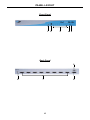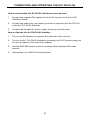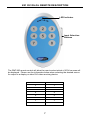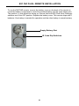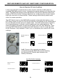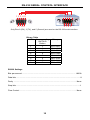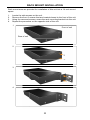
1
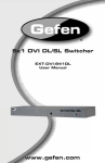
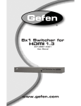
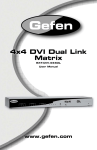
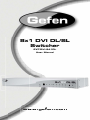
8x1 DVI DL/SL
Switcher
EXT-DVI-841DL
User Manual
www.gefen.com
f
ASKING FOR ASSISTANCE
Technical Support:
Telephone
Fax
(818) 772-9100
(800) 545-6900
(818) 772-9120
Technical Support Hours:
8:00 AM to 5:00 PM Monday thru Friday.
Write To:
Gefen Inc.
c/o Customer Service
20600 Nordhoff St
Chatsworth, CA 91311
www.gefen.com
[email protected]
Notice
Gefen Inc. reserves the right to make changes in the hardware, packaging and
any accompanying documentation without prior written notice.
8x1 DVI DL/SL is a trademark of Gefen Inc.
© 2008 Gefen Inc., All Rights Reserved
All trademarks are the property of their respective companies
Rev X1
CONTENTS
1
Introduction
2
Operation Notes
3
Features / Package Includes
4
Panel Descriptions
5
Panel Descriptions, Continued
6
Connecting and Operating the 8x1 DVI DL/SL Switcher
7
RMT-8IR Remote Description
8
RMT-8IR Remote Installation
9
IR Remote Control and 8x1 Switcher Configuration
10 RS-232 Serial Communication Interface
11 Rack Mount Installation
12 Specifications
13 Warranty
INTRODUCTION
Congratulations on your purchase of the 8x1 DVI DL/SL Switcher. Your complete
satisfaction is very important to us.
Gefen
Gefen delivers innovative, progressive computer and electronics add-on solutions
that harness integration, extension, distribution and conversion technologies.
Gefen’s reliable, plug-and-play products supplement cross-platform computer
systems, professional audio/video environments and HDTV systems of all sizes
with hard-working solutions that are easy to implement and simple to operate.
The Gefen 8x1 DVI DL/SL Switcher
The rack-mountable Gefen 8x1 single-link/dual-link DVI Switcher offers an
economical solution by eliminating the need to purchase many displays for each
computer in a studio or lab situation. A plug-and-play solution, the 8x1 DVI DL/
SL Switcher shares one dual-link display with up to eight computers or other DVI
video sources, saving space on your desktop. The source computer is selected
using the included IR remote control or through RS-232 control.
How It Works
The DVI monitor is connected to the switcher’s output. Up to eight DVI sources
connect to the switcher’s DVI inputs using included high quality DVI cables.
The included power supply is connected to the switcher via the locking power
plug and then to a power outlet. The currently selected computer’s video signal
appears on the shared monitor. Video sources are selected/switched using the
RMT-8IR remote control, RS-232 control, or the input selector push button on the
front panel of the switcher.
1
OPERATION NOTES
READ THESE NOTES BEFORE INSTALLING OR
OPERATING THE GEFEN 8X1 DVI DL/SL SWITCHER
•
The 8x1 DVI DL/SL Switcher will take any of up to eight (8) DVI dual-link or
single-link resolution inputs and switch them, one at a time, to a DVI output
device such as a display/monitor or projector. Resolutions can be up to
3840x2400.
2
FEATURES
Features
•
Switches easily between any eight DVI-SL or DVI-DL sources
•
Maintains highest resolution dual link DVI
•
Supports resolutions up through 3840x2400
•
Extends the range of DVI video up to 50 feet
•
Discrete IR remote control included
•
Serial RS-232 remote port for switching via automated control or PC
•
Supports DDWG standards for DVI monitors
•
Rack ears included
Package Includes
(1) 8x1 DVI DL/SL Switcher
(1) RMT-8IR Remote Control
(1) 5V DC Power Supply
(8) 6-foot Dual Link DVI cables
(1) Set of rack ears
(1) User’s Manual
3
PANEL LAYOUT
Front Panel
1 2
3
4 5
Back Panel
9
6
7
8
4
PANEL DESCRIPTIONS
1
External IR Port
For connection of external IR extension device such as the Gefen IR Extender
(part # EXT-RMT-EXTIR).
2
IR Receiver
Receives IR signal from the handheld Infrared remote control unit included with
the product.
3
DVI Signal Status LEDs 1-8
Provide visual confirmation of the currently selected DVI input signal out of the
eight DVI input ports.
4
DVI Input Selector
Push-button switch cycles the next DVI input 1-8 in a forward sequence starting
again at 1.
5
Power Indicator LED
Indicates when the 8x1 DVI DL/SL Switcher is receiving 5V DC power from its
included AC power supply.
6
5V Locking Power Receptacle
Supplies power to the 8x1 DVI DL/SL Switcher from the included external 5V
DC power supply. The 5V power supply has a locking power tip which screws
into this receptacle.
7
DVI Input Ports 1-8
DVI video sources one through eight attach to the 8x1 DVI DL/SL Switcher.
8
DVI Output Port
This DVI output port is connected to the display device (Monitor, Projector).
9
RS-232 Serial Communications Interface
Provided for external control of the 8x1 DVI DL/SL Switcher.
5
CONNECTING AND OPERATING THE 8X1 DVI DL/SL
How to Connect the 8x1 DVI DL/SL Switcher to your devices:
1.
Connect the supplied DVI cables from the DVI sources into the 8x1 DVI
Switcher’s Inputs.
2.
Connect the cable from your display (monitor or projector) into the DVI Out
of the 8x1 DVI DL/SL Switcher.
3.
Connect the included 5V power supply, then plug it into the wall.
How to Operate the 8x1 DVI DL/SL Switcher:
1.
Turn on the DVI display or projector first, then the video sources.
2.
Turn on the 8x1 DVI DL/SL Switcher by screwing its 5V DC power supply tip
into the receptacle in the rear of the chassis.
3.
Use the RMT-8IR remote control to remotely switch between DVI video
sources.
4.
Alternatively, use a RS-232 control system.
6
8X1 DVI DL/SL REMOTE DESCRIPTION
LED Indicator
Input Selection
Buttons
The RMT-8IR remote control will allow the user to select which of 8 DVI sources will
be displayed. Please use the information below when selecting the desired source
for output to a display or other DVI video receiving device.
RMT-8IR Button
DVI Source
1
1
2
2
3
3
4
4
5
5
6
6
7
7
8
8
7
8X1 DVI DL/SL REMOTE INSTALLATION
To use the RMT-8IR remote, remove the battery cover on the back of the remote to
reveal the battery compartment. Insert the included battery into the open battery slot.
The positive (+) side should be facing up. Ensure that both DIP (Dual Inline Package)
switches are in the OFF position. Replace the battery cover. The remote ships with 2
batteries. One battery is needed for operation and the other battery is complimentary.
Empty Battery Slot
IR Code Dip Switches
8
RMT-8IR REMOTE AND 8X1 SWITCHER CONFIGURATION
How to Resolve IR Code Conflicts
In the event that IR commands from other remote controls conflict with the
supplied RMT-8IR remote control, changing the remote channel will alleviate this
issue. The RMT-8IR remote control and the 8x1 DVI DL/SL Switcher both have
banks of DIP (Dual Inline Package) Switches for configuring the remote channel
that both units use to communicate. These settings must exactly match each
other for proper operation.
The DIP Switch bank on the RMT-8IR is located underneath the battery cover.
DIP Switch banks for the 8x1 DVI DL/SL Switcher are located on the underside of
the unit beneath a black piece of metallic tape. One DIP switch bank (4-switch)
is for the adjustment of remote control frequencies and switch behavior. The
other DIP switch (8-switch) is reserved for Gefen use only. DIP Switches 1 and
2 on the RMT-8IR directly correspond to DIP Switches 1 and 2 on the 8x1 DVI
DL/SL Switcher. Only switches 1 and 2 (of 4 in that bank) are used for IR Code
settings.
Remote Channel 1:
Default
Remote Channel 2:
1
2
Remote Channel 3:
1
2
1
2
Remote Channel 4:
1
2
Left: Picture of the opened rear battery
compartment of the RMT8-IR remote showing
the exposed DIP Switch bank between the
battery chambers.
8x1 DVI DL/SL Switcher
Remote Channel 1:
Default
Remote Channel 2:
1 2 3 4
1 2 3 4
Remote Channel 3:
Remote Channel 4:
1 2 3 4
1 2 3 4
9
RS-232 SERIAL CONTROL INTERFACE
12345
12345
6789
6789
Only Pins 2 (RX), 3 (TX), and 5 (Ground) are used on the RS-232 serial interface
Binary Table
ASCII Corresponding
RMT8-IR
Button
1
1
2
2
3
3
4
4
5
5
6
6
7
7
8
8
Binary
0011 0001
0011 0010
0011 0011
0011 0100
0011 0101
0011 0110
0011 0111
0011 1000
RS232 Settings
Bits per second ................................................................................................. 19200
Data bits .................................................................................................................... 8
Parity .................................................................................................................. None
Stop bits .....................................................................................................................1
Flow Control ....................................................................................................... None
10
RACK MOUNT INSTALLATION
Rack mount ears are provided for installation of this unit into a 1U rack mount
space.
1.
2.
3.
4.
Locate the side screws on the unit.
Remove the front 2 screws that are located closest to the front of the unit.
Using the removed screws, screw the rack mounting bracket into the unit.
Repeat the procedure on the opposite side of the unit.
1
Front of unit
Rear of unit
2
3
4
11
SPECIFICATIONS
Video Amplifier Bandwidth:..................................................................165 MHz x 2
Input Video Signal:...............................................................................1.2 Volts p-p
Input DDC Signal:..........................................................................5 Volts p-p (TTL)
Single Link Range:...............................................................................1920 x 1200
Dual Link Range :................................................................................ 3840 x 2400
DVI Connector:.................................................... DVI-I 29-pin female (digital only)
Power Supply:...............................................................................................5V DC
Power Consumption:........................................................................20 Watts (max)
Dimensions:...................................................................17” W x 1.75” H x 4.375” D
Rackmountable:..............................................................................1U Rack Space
Shipping Weight:...........................................................................................12 lbs.
12