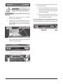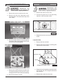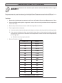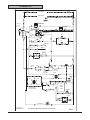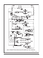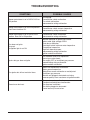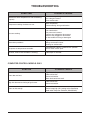
1
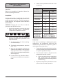
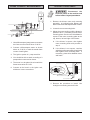
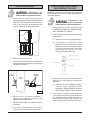
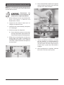
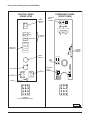
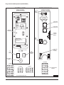
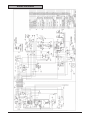
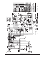
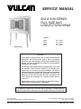
SERVICE MANUAL
SG4 & SG6 SERIES
FULL SIZE GAS
CONVECTION OVENS
MODELS
SG4D
SG4C
SG6D
SG6C
ML-114875
ML-114876
ML-114877
ML-114878
Model SG4D
- NOTICE This manual is prepared for the use of trained Vulcan Service
Technicians and should not be used by those not properly
qualified. If you have attended a Vulcan Service School for this
product, you may be qualified to perform all the procedures
described in this manual.
This manual is not intended to be all encompassing. If you have
not attended a Vulcan Service School for this product, you
should read, in it's entirety, the repair procedure you wish to
perform to determine if you have the necessary tools, instruments
and skills required to perform the procedure. Procedures for
which you do not have the necessary tools, instruments and
skills should be performed by a trained Vulcan Service
Technician.
Reproduction or other use of this Manual, without the express
written consent of Vulcan-Hart, is prohibited.
For additional information on Vulcan-Hart or to locate an authorized parts
and service provider in your area, visit our website at www.vulcanhart.com
P.O. BOX 696, LOUISVILLE, KY 40201-0696
TEL. (502) 778-2791
VULCAN-HART
DIVISION OF ITW FOOD EQUIPMENT GROUP, LLC
WWW.VULCANHART.COM
–1–
FORM 35626 Rev. A (02-08)
© VULCAN-HART, 2008
–2–
TABLE OF CONTENTS
GENERAL .............................................................................................................................................................. 5
Introduction ...............................................................................................................................................
Installation ................................................................................................................................................
Operation ...................................................................................................................................................
Cleaning ....................................................................................................................................................
Lubrication .................................................................................................................................................
Specifications ...........................................................................................................................................
Electrical Data ....................................................................................................................................
Gas Data .............................................................................................................................................
Tools .........................................................................................................................................................
Standard .............................................................................................................................................
Special ................................................................................................................................................
5
5
5
5
5
5
5
5
5
5
5
REMOVAL AND REPLACEMENT OF PARTS ..................................................................................................... 6
Component Location ................................................................................................................................. 6
Covers and Panels ................................................................................................................................... 7
Top Front Cover .................................................................................................................................. 7
Bottom Front Cover ............................................................................................................................ 7
Control Panel ...................................................................................................................................... 7
Right Side Panel ................................................................................................................................. 7
Control Panel Components ....................................................................................................................... 8
Procedure ........................................................................................................................................... 8
Component Panel Components ................................................................................................................ 9
Procedure ........................................................................................................................................... 9
Temperature Probe .................................................................................................................................. 10
Gas Burners ............................................................................................................................................. 11
Gas Orifice ...............................................................................................................................................12
Gas Solenoid Valve ................................................................................................................................. 12
Ignition Control Module ............................................................................................................................ 13
Spark Igniter and Flame Sense ............................................................................................................... 13
Blower and Motor ..................................................................................................................................... 14
Oven Doors and Bearings ....................................................................................................................... 15
Roller Latch Assembly ............................................................................................................................. 16
Door Catch Assembly .............................................................................................................................. 16
Door Window ............................................................................................................................................ 16
Door Switch .............................................................................................................................................. 17
High Limit Thermostat ............................................................................................................................. 18
Interior Lights ........................................................................................................................................... 18
Lamp Assembly ................................................................................................................................. 18
Cooling Fan .............................................................................................................................................. 19
Fan Installation Tips .......................................................................................................................... 19
SERVICE PROCEDURES AND ADJUSTMENTS ...............................................................................................20
Solid State Temperature Controller Test (SG4D/SG6D) ........................................................................ 20
Test Steps .........................................................................................................................................20
Solid State Temperature Controller Calibration (SG4D/SG6D) ..............................................................21
Calibration Steps ...............................................................................................................................21
Calibration Tips ................................................................................................................................. 21
Temperature Probe Test (SG4D/SG6D) ................................................................................................. 22
Test Steps .........................................................................................................................................22
–3–
TABLE OF CONTENTS (Cont.)
Computer Controller (SG4C/SG6C) ......................................................................................................... 23
Operation ........................................................................................................................................... 23
Setup Mode ....................................................................................................................................... 23
Probe Test .........................................................................................................................................23
Solid State Relay Test ...................................................................................................................... 24
Computer Controller Calibration (SG4C/SG6C) ....................................................................................... 24
Calibration Steps ...............................................................................................................................24
Gas Pressure Adjustment .......................................................................................................................25
Verification of Spark at Igniter ................................................................................................................ 26
Door Switch Adjustment .......................................................................................................................... 26
Flame Current Measurements ................................................................................................................. 27
Blower Adjustment ................................................................................................................................... 27
Door Adjustment ...................................................................................................................................... 28
Door Strike Adjustment ............................................................................................................................ 28
Door Catch Roller Adjustment ................................................................................................................. 29
ELECTRICAL OPERATION ................................................................................................................................. 30
Component Description ........................................................................................................................... 30
Plug, Socket and Components (SG4D/SG6D) ........................................................................................ 31
Plug, Socket and Components (SG4C/SG6C) ........................................................................................ 32
Sequence of Operations ..........................................................................................................................33
SG4D/SG6D with Solid State Temperature Controller ..................................................................... 33
Cook Cycle ........................................................................................................................................ 33
Timer Cycle ....................................................................................................................................... 34
Cool Down Cycle (Solid State Temperature Controller) ................................................................... 34
SG4C/SG6C with Computer Controller ............................................................................................. 35
Normal Cook Cycle ..................................................................................................................... 35
Temperature and Time Cycle (Normal Cooking) ............................................................................... 37
Function Switch (SG4C/SG6C) ......................................................................................................... 37
Roast and Hold Cycle ........................................................................................................................ 37
Wiring Diagrams ....................................................................................................................................... 38
Schematics .............................................................................................................................................. 40
TROUBLESHOOTING .......................................................................................................................................... 42
Error Codes .............................................................................................................................................. 44
–4–
GENERAL
INTRODUCTION
Procedures in this manual will apply to all models unless specified. Pictures and illustrations can be of any model
unless the picture or illustration needs to be model specific. All models are equipped with a two-speed 1/2 HP electric
motor, porcelain interior and two 30,000 BTU/hr burners as standard equipment. A power level control permits
variable burner input from 15,0000 BTU/hr to 60,000 BTU/hr.
Models SG4D and SG6D are equipped with solid state-controls and a 60-minute timer (a 5-hour timer is optional).
Models SG4C and SG6C have a computer control with built-in Roast & Hold.
Models SG6D and SG6C have a 4" deeper cavity than models SG4D and SG4C.
Gas Data
INSTALLATION
Model
Generally, installations are made by the dealer or
contracted by the dealer or owner. Detailed installation
instructions are included in the Installation & Operation
Manual which is sent with each unit.
SG4D,
SG4C,
SG6D,
SG6C
Input BTU/hr
Manifold Pressure
Natural
LP Gas
Natural
LP Gas
60,000
60,000
3.5" W.C.
(0.9 kPa)
10" W.C.
(2.2 kPa)
TOOLS
OPERATION
Detailed operation instructions are included with each
oven.
Standard
• Hand tools (standard set).
• VOM with AC current tester (any quality VOM
with a sensitivity of at least 20,000 ohms per
volt can be used).
CLEANING
Detailed cleaning procedures are included in the
Installation & Operation Manual for the appropriate
model.
• Gear puller to remove blower.
Special
LUBRICATION
• Temperature tester (thermocouple type).
Motor bearings are sealed and prelubricated.
• Manometer
SPECIFICATIONS
Electrical Data
Model
Volts
Hertz
Phase
Amps
SG4D
SG4C
SG6D
SG6C
120
60
1
7.5
208
60
1
3.6
240
60
1
3.75
–5–
REMOVAL AND REPLACEMENT OF PARTS
COMPONENT LOCATION
TOP VIEW
BLOWER MOTOR
OVEN LIGHTS
COOLING
FAN
TEMPERATURE PROBE
GAS BURNERS
COMPONENT
PANEL
IGNITER &
FLAME SENSE
GAS VALVE
HIGH LIMIT
DOOR
SWITCH
CONTROL
PANEL
PL-56044
–6–
Control Panel
COVERS AND PANELS
1. Remove three screws on the right side which
secure the control panel. Pull the panel away
from the oven.
Disconnect the
electrical power to the machine and
follow lockout / tagout procedures.
CONTROL
PANEL
Top Front Cover
MASTER SWITC H
OVEN
COOL
1. The top front cover is secured with four
screws, two on each side of cover. Remove
these screws, then remove the cover from
the oven.
OFF
THERMOSTAT
POWER LEVEL
REMOVE SCREWS
FAN SPEED
HI
LOW
REMOVE
SCREWS
LIGHTS
ON
OFF
TOP FRONT COVER
SG4D SHOWN
PL-56042-1
MASTER SWITCH
2. Disconnect the temperature probe leads from
the solid state temperature controller.
OVEN
COOL
OFF
ON
HEAT
3. Unplug the wire harness connector to the
control panel components.
IGNITION
4. Reverse the procedure to install.
PL-56040
Right Side Panel
2. Reverse the procedure to install.
1. Remove the screws that secure the right side
of the control panel.
Bottom Front Cover
2. Remove the remaining screws securing the
right side panel.
1. The bottom front cover is secured with six
screws, two on each side of cover and two on
the top. Remove these screws then remove
the cover from the oven.
3. Pull the right-side panel out at the bottom
then down to remove.
REMOVE SCREWS
RIGHT SIDE
REMOVE
SCREWS
BOTTOM FRONT COVER
PL-56041
PL-56043
2. Reverse the procedure to install.
4. Reverse the procedure to install.
–7–
CONTROL PANEL COMPONENTS
MAS
TER
MASTER
SWITCH
SWIT
CH
OVE
N
COO
L
ON
OFF
O N / H E AT
I N D I C ATO R
LIGHTS
NO IGNITION
LIGHT
THE
RMO
STAT
COMPUTER
CONTROLLER
T E M P E R AT U R E
C O N T RO L L E R
( T H E R M O S TAT )
0
55
50
45
40
35
30
25
POW
ER LE
VEL
P OW E R C O N T RO L
TIME
R
NO IGNITION
LIGHT
TIMER
0
55
50
45
40
35
30
POWER
SWITCH
25
FAN
FA N S P E E D
SWITCH
SPEE
POW
ER
ON
D
ON
HI
ON
LIGH
TS
OFF
LIGH
TS
LOW
OFF
OVE
N
COO
L
LIGHT
SWITCH
SG4D/SG6D
LIGHT
SWITCH
OFF
SG4C/SG6C
PL-56046
PL-56045-1
Procedure
Disconnect the electrical power to the machine and follow lockout / tagout
procedures.
1. Remove the control panel as outlined under Covers and Panels.
2. Remove the component being replaced.
3. Reverse the procedure to install the new component, then check oven for proper operation.
–8–
COMPONENT PANEL COMPONENTS
PORCELAIN
BLOCK
ASSEMBLY
PORCELAIN
BLOCK
ASSEMBLY
TRANSFORMER
TRANSFORMER
MOTOR
CONTROL
RELAYS
HEATING
RELAY
IGNITION
MODULE
BOARD
IGNITION
MODULE
BOARD
IGNITION
MODULE
IGNITION
MODULE
HEATING
RELAY
PORCELAIN
BLOCK
ASSEMBLY
PORCELAIN
BLOCK
ASSEMBLY
SG4D/SG6D
PL-56047
SG4C/SG6C
PL-56048
Procedure
Disconnect the electrical power to the machine and follow lockout / tagout
procedures.
1. Remove the right side panel as outlined under Covers and Panels.
2. Disconnect the wire leads to the component being replaced.
3. Remove the component.
4. Reverse the procedure to install the new component and check oven for proper operation.
–9–
7. Remove the probe from the bracket(s).
TEMPERATURE PROBE
Disconnect the
electrical power to the machine and
follow lockout / tagout procedures.
1. Remove the right-side panel as outlined under
Covers and Panels.
2. Disconnect probe leads from the solid state
temperature controller on the SG4D/SG6D or
the computer controller on the SG4C/SG6C.
3. Remove the racks and right rack support.
4. Remove the upper and lower door seals.
SG4C/SG6C Temperature Probe Shown
8. Push the probe through the oven wall and into
the control panel area.
9. Reverse the procedure to install the new
probe.
10. Calibration:
A. SG4D/SG6D: Adjust the temperature
controller as outlined under Solid State
Control Calibration.
B. SG4C/SG6C: Adjust the computer
controller as outlined under Computer
Controller and/or Computer Controller
Calibration in Service Procedures and
Adjustments.
5. Loosen the three screws securing the right
side air scoop to the rear heat exchanger.
Rotate the air scoop off of the heat exchanger
tube into the oven cavity.
6. Remove the screws that secure the perforated
side panel and lift out.
– 10 –
GAS BURNERS
5. Reverse the procedure to install and check
for proper operation.
Disconnect the
electrical power to the machine and
follow lockout / tagout procedures.
A. Ensure the spacers are in place on the
ignition wires. The spacers are intended
to keep the ignition wires from laying flat
on the oven chassis.
Shut off the gas before servicing
B. Ensure that the bracket on the back of
the burner is inserted into the slot at the
rear of the burner chamber.
the oven.
1. Remove the lower front cover as outlined
under Covers and Panels.
Note: Check the flame current by following the Flame
Current Measurement procedures under the
Procedures and Adjustments Section of this manual.
2. There are two burners located on the bottom
left and right side of the oven. Disconnect the
ignition cable and the flame sense lead from
each burner.
3. Remove the bolts securing the gas manifold
and place manifold aside.
4. Grasp the burner and lift out.
– 11 –
3. Disconnect compression fittings from the
valve.
GAS ORIFICE
Disconnect the
electrical power to the machine and
follow lockout / tagout procedures.
Shut off the gas before servicing
the oven.
1. Remove the lower front cover as outlined
under Covers and Panels.
2. Remove the bolts securing the gas manifold
and place manifold aside.
4. Loosen the bolts securing the valve and
bracket assembly, then remove the screws
securing the valve to the bracket.
3. There are two gas orifices on the manifold.
Remove each orifice and replace with the
correct orifice for the given altitude as needed.
4. Reverse the procedure to install manifold and
check for proper operation.
GAS SOLENOID VALVE
Disconnect the
electrical power to the machine and
follow lockout / tagout procedures.
5. Reverse the procedure to install the
replacement gas valve.
All gas joints disturbed during
servicing must be checked for leaks. Check with
soap and water solution (bubbles). Do not use an
open flame.
Shut off the gas before servicing
the oven.
1. Remove the control panel and the right side
panel as outlined under Covers and Panels.
6. Verify gas pressure as outlined under the
Gas Pressure Adjustment in Service
Procedures and Adjustments. Check for
proper operation.
2. Disconnect the lead wires.
– 12 –
IGNITION CONTROL MODULE
SPARK IGNITER AND FLAME SENSE
Disconnect the
electrical power to the machine and
follow lockout / tagout procedures.
Disconnect the
electrical power to the machine and
follow lockout / tagout procedures.
1. Remove the right side cover as outlined
under Covers and Panels.
Shut off the gas before servicing
the oven.
2. Loosen the screws securing the mounting
bracket to the component panel and remove
the bracket.
1. Remove the two gas burners as outlined
under Gas Burners.
2. Remove the screws securing the igniter and
flame sense to each burner. Remove the
assembly.
3. Disconnect the lead wires and igniter cables
from the ignition module board.
3. The spark gap is 1/8" from the inside of the
spark rod to the inside to the ground rod. The
ground rod (the end of the spark) is 1/ 8" above
the burner. If the gap is not correct or poor
sparking is occurring, then adjust accordingly.
4. Remove the ignition module board from the
mounting bracket.
5. Reverse the procedure to install the
replacement ignition module board.
6. Check for proper operation.
4. Reverse the procedure to install the assembly
and check for proper operation.
– 13 –
5. Remove the screws that secure the motor
mounting plate to the rear wall.
BLOWER AND MOTOR
Disconnect the
electrical power to the machine and
follow lockout / tagout procedures.
1. Remove racks.
2. Remove the screws securing the snorkel and
remove the snorkel.
6. Place a piece of cardboard on the bottom of
the oven cavity to protect its surface from
any damage during motor assembly removal.
7. Pull the motor assembly into the oven cavity
and place it on the cardboard.
8. Remove the junction box cover from the
motor, disconnect lead wires and remove the
conduit.
9. Remove motor mounting bolts and flat
washers, then lift the motor from the mounting
plate.
3. Remove screws securing baffle panel and
remove the panel.
10. Position the replacement motor on the motor
mounting plate and install mounting bolts and
washers. Hand tighten mounting bolts only.
4. If replacing:
A. Blower Only - Loosen set screws on
blower hub and using a bearing puller,
remove blower from motor shaft.
11. Reconnect to lead wires at the motor, and
replace conduit and junction box cover.
1) Reverse procedure to install and
adjust blower position as outlined
under the Blower Adjustment in
Service Procedures and Adjustments
section.
B. Motor - Perform step 4A and continue
procedure.
– 14 –
OVEN DOORS AND BEARINGS
FRONT VIEW OF MOTOR
FROM INSIDE OVEN CAVITY
Disconnect the
electrical power to the machine and
follow lockout / tagout procedures.
1. Remove the top front cover and bottom front
cover as outlined under Covers and Panels.
2. Remove the door switch lever.
MOTOR ROTATES CLOCKWISE
PL-56051
12. Slide blower onto motor shaft until hub is
flush with end of shaft, then tighten setscrews.
13. Adjust motor position until blower is parallel
to motor mounting plate as outlined in Blower
Adjustment under Service Procedures and
Adjustments.
3. Remove the lower door seal strip to expose
the mounting screws of the door assembly.
4. Remove the two lower sill bolts by the lower
door shaft and the four countersunk screws
from the lower sill.
14. Position motor mounting plate on the rear
wall and secure with nuts and washers.
15. Replace the baffle panel and snorkel.
16. Replace the air baffle on the rear wall at the
lower right hand corner.
17. Remove cardboard from the bottom of the
oven cavity.
18. Install racks.
A. The door assembly is heavy and will drop
down once the last screw is removed. If
removing the door assembly without
assistance, the ignition cable, flame
sense lead and gas manifold should also
be removed to avoid damage to these
components.
19. Check oven for proper operation.
5. Tilt the top of the door slightly forward and lift
the door up until the bottom of the door shaft
clears the opening in the sill.
6. Lay the door flat to prevent damage.
– 15 –
7. The top and bottom bearings are now
accessible for inspection and/or replacement
if needed.
DOOR CATCH ROLLER ASSEMBLY
(INDEPENDENT DOORS)
NOTE: For units with serial number starting with 48
made before 8/13/07 and serial number starting with
54 made before 8/27/07.
A. If bearings are OK, proceed to step 8.
B. If replacing the top bearing, remove the
top bearing retainer and top bearing.
Disconnect the
electrical power to the machine and
follow lockout / tagout procedures.
1. Remove the top front cover as outlined under
COVERS AND PANELS.
2. Remove the nuts and bolts that secure the
door catch assembly.
C. If replacing the bottom bearing, remove it
from the door shaft or the lower sill
opening.
8. Reverse procedure to install door assembly
and check for proper operation as outlined
under the Door Adjustment and Door Switch
Adjustment section in Procedures and
Adjustments.
3. Reverse the procedure to install.
4. Adjust the roller catch as outlined under the
Door Catch Adjustment in Service Procedures
and Adjustments.
ROLLER LATCH ASSEMBLY
(INDEPENDENT DOORS)
DOOR WINDOW
NOTE: For units with serial number starting with 48
made after 8/12/07 and serial number starting with 54
made after 8/26/07.
Disconnect the
electrical power to the machine and
follow lockout / tagout procedures.
Disconnect the
electrical power to the machine and
follow lockout / tagout procedures.
1. Remove the screws at the top and bottom of
the door.
1. Remove the screws that attach roller latch
assembly to door.
OVEN CAVITY
2. Reverse procedure to install.
REMOVE
SCREWS
GLASS
PL-56052
– 16 –
2. Remove the door handle, then remove the
outer door panel.
DOOR SWITCH
3. Lift out the inner door panel window assembly.
Disconnect the
electrical power to the machine and
follow lockout / tagout procedures.
4. Remove the door seal from the inside of the
left door only.
5. Remove the screws securing the window
tabs to the door bracket and lift the window
assembly out from the door frame.
1. Remove the top front cover as outlined under
Covers and Panel.
2. Disconnect the lead wires to the door switch.
INNER DOOR PANEL ASSEMBLY
GLASS
REMOVE
SCREWS
3. Remove the switch.
GLASS
4. Reverse procedure to install the replacement
switch and check for proper adjustment as
outlined in Door Switch under Service
Procedures and Adjustments.
PL-56053
6. Reverse procedure to install the replacement
window.
– 17 –
INTERIOR LIGHTS
HIGH LIMIT THERMOSTAT
Disconnect the
electrical power to the machine and
follow lockout / tagout procedures.
Disconnect the
electrical power to the machine and
follow lockout / tagout procedures.
1. Remove the top four racks from the oven.
1. Remove the racks from the oven.
2. Remove the high limit thermostat cover/
mounting plate. It is located at the top of the
oven cavity.
2. Unscrew the glass lens for the light being
replaced, then unscrew the bulb.
LENS
LENS
OVEN CAVITY
PL-56054
3. Replace bulb, then reverse the procedure to
install.
3. Disconnect the lead wires from the high limit
thermostat. Remove the high limit thermostat
from the cover mounting plate.
Lamp Assembly
1. Remove the lens and bulb.
2. Remove the springs from the retaining tabs
(two places) on the socket.
RETAINING TABS
SPRING
CROSS SECTIONAL VIEW
PL-56055
3. Depress the retaining tabs and pull the socket
out from the oven, far enough to disconnect
the lead wires.
4. Remove the old RTV silicone from the cover
and mating surfaces inside the oven cavity,
and apply new RTV silicone before installing.
4. Remove the socket from the oven.
5. Reverse procedure to install.
– 18 –
5. Attach the lead wires to the replacement
socket.
Fan Installation Tips
• The fan must be installed so air is pulled from
the rear of the oven and blown into the control
area. The arrow on the fan body indicates
airflow direction and should be pointing toward
the controls.
NOTE: Ensure the case is connected to the
green ground wire.
6. Insert the socket into the hole in the oven and
push until the socket is held in place by the
retaining tabs.
• Ensure the fan is seated squarely against the
air tube and the oven bottom.
7. Install the light bulb and lens.
• The air deflector should be angled upward at
approximately 30 degrees to properly direct
the airflow.
8. Check for proper operation.
COOLING FAN
Disconnect the
electrical power to the machine and
follow lockout / tagout procedures.
1. Remove the right side panel as outlined under
Covers and Panels.
2. Disconnect the lead wires to the fan motor by
removing the wire nuts.
3. Remove the screws securing the air deflector
to the fan, then loosen the tab screw holding
the fan to the component panel. Rotate the
tab so that the fan will clear. Remove the fan.
4. Reverse the procedure to install the
replacement fan and check for proper
operation.
– 19 –
SERVICE PROCEDURES AND ADJUSTMENTS
Certain procedures in this section require electrical test or measurements while power is
applied to the machine. Exercise extreme caution at all times. If test points are not easily accessible, discern
power, attach test equipment and reapply power to test.
8. Check for voltage to the switching output.
SOLID STATE TEMPERATURE
CONTROLLER TEST
(SG4D/SG6D)
a.
For 120 VAC controls, check across
terminals J3 and J4 for input voltage and
between J4 and J5 for output voltage
from the internal switching device.
b.
For 208/240 VAC controls, check across
terminals J3 and J9 for input voltage and
between J9 and J5 for output voltage
from the internal switching device.
Test Steps
1. Remove the right side panel as outlined
under Cover and Panels in Removal and
Replacement of Parts.
2. Place a thermocouple in the geometric center
of the oven cavity. Oven temperature must
be below 450°F.
1) If input voltage is correct, proceed to
step 9. If input voltage is not present,
the problem is not in the controller
(See Troubleshooting).
3. Set the temperature control to the maximum
setting.
2) If output voltage is correct, proceed
to step 9. If output voltage is not
correct, check temperature probe,
as outlined under Temperature Probe
Test (SG4D/SG6D).
4. Set the power control to 100%.
5. Check machine data plate for correct voltage
to oven. Refer to diagram below for proper
terminal locations and voltages before
checking temperature controller. Use the
correct terminals for the corresponding
voltage.
c.
6. Turn the ON-OFF-OVEN-COOL switch to
ON.
If the probe connected to J6 and J7 is
either shorted or opened, the red LED
located just above J6 (to the left of J6
when mounted) will flash. With the probe
connected and the LED not flashing,
slowly turn the Temperature set knob
until the pointer passes through the mid
point of rotation. At the mid point of
rotation, the red LED will come on. If the
control is set and left at the mid point, the
LED will stay on. With the LED on at mid
point, you have tested the entire front
end of the control circuit as well as the
probe and verified that the control is
functioning normally.
9. Set temperature control to minimum setting.
Oven temperature must be above 300°F.
10. Check for zero volts (0.00 Volts) across
terminals J4 and J5 (120 Volt) or J9 and J5
(208/240 Volt) for no output from the internal
switching device.
7. Check for voltage across terminals J2 and J4
(120 Volt) or J2 and J9 (208/240 Volt) for
power to the control.
a.
a. If correct, proceed to step 8.
b. If incorrect, the problem is not in the
temperature
control
(see
Troubleshooting).
– 20 –
If correct, temperature control is
functioning properly.
b.
7. Calculate the average oven temperature by
adding the actual minimum temperature to
the actual maximum temperature and dividing
by 2.
If incorrect, check temperature probe as
outlined under Temperature Probe Test
(SG4D/SG6D).
1) If temperature probe is functioning
properly and the temperature
controller failed the test in 8c above,
replace the temperature control and
check for calibration as outlined under
Solid State Temperature Controller
Calibration (SG4D/SG6D).
EXAMPLE:
Oven set to 350°F.
Actual minimum oven temperature = 335°F
Control cuts on at 334°F
Actual maximum oven temperature = 347°F
Control cuts off at 340°F
335 + 347 = 682
682/ 2 = 341 (the control is 9°F out of calibration)
340 - 334 = 6°F Control Differential
347 - 335 = 12°F Oven Temperature Differential
SOLID STATE TEMPERATURE
CONTROL CALIBRATION
(SG4D/SG6D)
A. If the average oven temperature is within
+/- 5°F from the dial setting, no calibration
is necessary.
Before attempting any calibration, see Section 8C of
SOLID STATE TEMPERATURE CONTROLLER
TEST (SG4D/SG6D) on previous page.
B. If the average oven temperature is not
within +/- 5°F, calibration is
recommended.
Calibration Steps
8. Loosen the set screw on the temperature
controller and carefully remove the knob from
the shaft, without rotating the shaft. This will
expose the calibration adjustment control
access hole in the front panel.
1. Place a thermocouple in the geometric center
of the oven cavity.
2. Set the ON/OFF/OVEN COOL switch to ON.
3. Set the temperature controller dial to 350°F.
Set the power control to 100% (10).
9. Monitor the internal oven temperature and
determine at what temperature the control
should cut on to give you the required minimum
temperature (Example: 350-341=9;
334+9=341. 341°F is the temperature at which
you would wish the controller to cut on).
4. Allow the oven temperature to stabilize
(minimum three heating cycles).
5. Record the temperature at which the Heat
lamp comes ON (heating starts) and goes
OFF (heating stops). This is the control
differential. Heat lamp OFF temp - Heat lamp
ON temp = Control Differential.
10. After allowing the oven to operate through
several cycles (minimum 3 cycles), monitor
the temperature as it falls to the desired "cuts
on" point. Using a small screw driver, adjust
the calibration adjustment until the controller
cuts on at the desired "cuts on" temperature.
6. The nominal control differential should be
less than 20°F.
A. If the control differential is less than
20°F, the temperature control circuit is
functioning properly. Proceed to step 7.
11. The calibration control is adjusted clockwise
in order to increase the set temperature and
counter clockwise to decrease the set
temperature.
B. If the control differential is more than
20°F, check the temperature probe as
outlined under Temperature Probe Test
(SG4D/SG6D).
12. The controller has only +/- 25°F of adjustment.
1
/4 turn of the calibration adjustment represents
approximately 20°F shift in calibration.
C. If the control differential is more than
20°F and the probe passes its' test
parameters, then temperature controller
is malfunctioning. Install a new
temperature controller and run calibration
steps again.
– 21 –
TEMPERATURE PROBE TEST (SG4D/SG6D)
Disconnect the electrical power to the machine and follow lockout / tagout
procedures.
The temperature probe used in conjunction with the Solid State Temperature controller is an RTD (resistance
temperature detector) of the Thermistor type. As temperature increases the resistance value decreases.
Test Steps
1. Remove the right side panel as outlined under Cover and Panels in Removal and Replacement of Parts.
2. Place a shielded thermocouple in the geometric center of the oven cavity and determine the temperature
in the oven cavity.
3. Remove the probe lead wires from the solid state temperature controller.
4. Test the probe with an ohmmeter.
A. If the measured resistance values are inside the given tolerance, then the probe is functioning properly.
B. If the measured resistance values are outside the given tolerance, then replace the probe and make
sure wires are secured to the terminals of the temperature controller. Recheck the temperature by
preforming step 2.
1)
Check the oven for proper operation.
5. Reverse Procedure to install.
TEMP (°F)
OHMS*
77
90,000
240
4,077
260
3,016
280
2,266
300
1,726
320
1,332
340
1,041
360
822
380
656
400
529
425
424
450
334
475
266
(*) Resistance in ohms ± 10%
– 22 –
3. Listed are the parameters and data in the
setup mode.
COMPUTER CONTROLLER
(SG4C/SG6C)
ALTERNATING ON DISPLAY
Operation
MENU
Refer to the Installation & Operation Manual for
specific operating instructions.
Setup Mode
Use the setup mode to verify that the control is
configured to the factory settings which result in the
proper operation of the oven. If the CAL1 parameter
is other than zero, see Computer Control Calibration
(SG4C/SG6C).
CAUTION: Changing the C_F, InP1, rL1 and rH1
parameters will default all menus.
1. Use this key sequence to access the setup
mode: UP arrow, Rack 1, Temperature,
Temperature, DOWN arrow, Rack 1.
1
1
PARAMETER
DATA
Celsius_Fahrenheit
C_F
F
Guard Band
gb
4000
Temperature
Compenstaion
tcnP
OFF
Input Type 1
InP1
J
Range Low 1
rL1
75
Range High 1
rH1
500
Hysteresis
HYS1
3
Calibration Offset
CAL1
0
Exit setup mode
and return to
operation mode.
PL-56075
2. Once in the setup mode the display will
alternate between the parameter and
programmed data.
Set point temperature is
displayed or if calling for heat,
dashes (----) are displayed.
Probe Test
A. To change data to the factory setting,
use the arrow keys.
If the oven is not heating or displaying the proper
temperature, the temperature probe may be
malfunctioning. Determine if the probe is good or
causing the operational problem.
B. To select the next parameter, press the
Rack 1 key.
1. Temporarily disconnect the existing lead wires
from the computer control and connect them
to a good J-type thermocouple.
C. After the last parameter and data are
viewed, press the Rack 1 key to exit the
setup mode and return to operations
mode. The current set point temperature
will be displayed.
2. Turn the power switch to ON and set the
temperature controller to 350°F.
D. If there are no key activations after 1
minute, the control will return to operation
mode.
A. If the oven reaches the set temperature
and cycles with the temporary
thermocouple, then the existing probe is
malfunctioning.
3. Replace the temperature probe with the correct
part and check for proper operation.
– 23 –
C. Press the set key again to save the change,
then exit the temperature set mode.
Solid State Relay Test
1. Remove the right side panels as outlined
under Covers and Panels in Removal and
Replacement of Parts.
4. Allow the oven temperature to stabilize
(normally three cycles).
2. Turn the power switch to the ON position.
5. Compare the controls set point temperature
to the thermocouple meter reading when the
heat light goes out.
3. Check for +5 VDC on input side of SSR-1 in
the normal heating mode (terminals 3 & 4)
and SSR-2 in the roast and hold mode.
A. A temperature variance more than 5°F
indicates an adjustment is needed.
A. If +5 VDC is present, continue to step 4.
1) To make the adjustment, proceed to
step 6.
B. If no voltage is present, computer control
is not functioning properly.
4. Check for 120 VAC at load side of SSR
(terminals 1 & 2).
2) If temperature variances is less than
5°F, then the computer control is
functioning properly.
A. If no voltage is present, solid state relay
is not functioning properly.
6. Enter the setup mode as outline in Setup
Mode under Computer Control (SG4C/SG6C).
1) Replace the SSR and check for proper
operation.
A. Advance through the menu until CAL1
(calibration offset) appears.
B. If 120 VAC is present, component is
functioning properly.
1) If the thermocouple reading is higher
than set point temperature, press the
down arrow key and enter a negative
offset value that is equal to the
number of degrees above the 5°F
tolerance.
5. Reassemble oven and check for proper
operation.
2) If the thermocouple reading is lower
than set point temperature, press the
UP arrow and enter a positive offset
value that is equal to the number of
degrees below the 5°F tolerance.
COMPUTER CONTROL CALIBRATION
(SG4C/SG6C)
Calibration Steps
1. Place a thermocouple in the geometric center
of the oven cavity.
3) Exit the setup mode.
7. Allow the oven to cycle at least two times
between adjustments.
2. Set the ON-OFF-COOL DOWN switch to ON.
A. If the set point temperature is 350°F,
proceed to step 4.
A. If the temperature variance still differs
more than 5°F from the set point, verify
the correct calibration offset value was
entered and retained.
B. If the set point temperature is other than
350°F, proceed to step 3 to change the
temperature.
1) Adjust the calibration offset value as
outlined in step 6, until the cycling
temperature is within tolerance.
3. Press the set key then temperature key to
enter the temperature set mode.
B. If the above adjustment cannot be
obtained, replace the computer control
and check for proper operation.
A. The display will alternate between the
term StPt (set point) and the current
oven temperature setting.
B. Press the UP or DOWN arrows to make
the proper selection.
– 24 –
4. Install hose barb adapter and attach
manometer tube.
GAS PRESSURE ADJUSTMENT
Disconnect the
electrical power to the machine and
follow lockout / tagout procedures.
Accurate gas pressure adjustments can only be
made with the gas on and the burner lit. If the
incoming line pressure to the valve is less than the
minimum stated, then the manifold pressure cannot
be set correctly.
1. Turn gas supply off at manual shutoff valve.
2. Remove the right side panel as outlined
under Covers and Panels in Removal and
Replacement of Parts.
3. Remove the plug from the manifold pressure
port.
5. Remove adjustment screw cap from the gas
valve and turn gas supply to the oven back
on.
The following steps require power
to be applied to the unit during test. Use extreme
caution at all times.
6. Plug the unit in and turn the power switch ON.
7. Set the temperature controller to its highest
setting and allow burner to ignite. The burner
must be lit during test and adjustment.
8. Turn the set screw to obtain the proper gas
pressure (clockwise = pressure increase;
counterclockwise = pressure decrease).
PRESSURE READINGS (IN W.C.)
GAS
TYPE
LINE
MANIFOLD
RECOMMENDED
MIN
Natural
3.5
7.0
5.0
Propane
10
11.0
11.0
MAX
14
– 25 –
The following steps require power
to be applied to the unit during the test. Use
extreme caution at all times.
VERIFICATION OF SPARK AT IGNITOR
Disconnect the
electrical power to the machine and
follow lockout / tagout procedures.
4. Plug the oven in and set the temperature
controller to the maximum setting.
5. Turn the power switch ON.
6. Sparking should occur after a 4 second delay
and continue for 7 seconds. The cycle will
repeat twice after a 15 second purge time.
Arcing from the ignition cable to the oven
frame should be observed.
Shut off the gas before servicing
the oven.
1. Remove the bottom front cover as outlined
under Covers and Panels in Removal and
Replacement of Parts.
2. Disconnect the high voltage ignition cable
from the spark igniter.
DOOR SWITCH ADJUSTMENT
Disconnect the electrical power
to the machine and follow lockout / tagout
procedures.
1. Remove the top front cover as outlined under
Covers and panels in Removal and
Replacement of Parts.
2.
Do not hold the wire with your
hands for this test. The manual gas valve must be
closed.
Door operation:
A. The switch actuator is engaged by the
switch lever when the right door is between
1" and 1 1/ 2" from being closed.
3. Clamp the ignition cable in a manner that will
position the end of the cable 3/16" from the
oven frame (bare metal surface). It is critical
that the cable be held 3/ 16" away from the
surface of the oven frame or sparking may
not occur even though the sparking circuit is
functioning properly.
3. If adjustment is necessary, bend the switch
actuator to obtain the proper setting.
4. Install the top front cover.
5. Apply power to the oven and check for proper
operation.
– 26 –
BLOWER ADJUSTMENT
FLAME CURRENT MEASUREMENT
Disconnect the
electrical power to the machine and
follow lockout / tagout procedures.
MICROAMP METER
4
10
1. Remove the blower motor and mounting
assembly as outlined under Blower and
Motor in Removal and Replacement of Parts.
S1
56
55
V1
8
V2
59
57
C-2
NC
W
S1
S2
S1
1 2 3
RED
DIAGNOSTIC
INDICATOR
345519-4
424471-G1
LED
56
U
FENWAL
DUAL
CHANNEL
IGNITION
MODULE
52
T
LEFT
BURNER
24V
FC2GND
S2
FC1-
2
FC1+
48
RIGHT
BURNER
S2
2. Loosen the motor mounting bolts.
X
2
TH
3
SPARK
OUT
SPARK
OUT
FC2+
D
1
Y
2
3. Adjust the motor position until the blower is
parallel to and 1/4" inch away from the motor
mounting plate. Check to see if the blower is
square to the motor mounting plate at the
top, bottom, left and right of the blower.
L
1
V
6
57
L1
L2
48
5
W
46
GND.
WHITE
AB
AB
417856-1
GREEN
120 VOLT UNITS PROVIDED
WITH 3 PRONG GROUNDED
PLUG.
BLACK
CONNECT 200-240 VOLT
SUPPLY TO L1 & L2
A. If the blower is square, then tighten
motor mounting bolts and proceed to
step 4.
1. Use a Microampere (µamp) meter to measure
the flame current on both wires S1 & S2.
2. Connect a Microampere meter as shown
above to S1 & S2, to read the actual flame
current of each igniter.
B. If the blower is not square, continue
adjusting until proper spacing is achieved
then tighten motor mounting bolts. If
necessary, place shims between motor
and frame.
3. The ignition system is 1 µamp sensitive.
4. You should be able to attain a reading of 4
µamps when connected as shown.
5. The meter is to be placed in series with the
flame sense wires S1 & S2.
PLACE SHIMS UNDER REAR OF
MOTOR TO WIDEN TOP SPACE.
1/4 INCH AT
ALL PLACES
TOP
6. Connect at the board or the igniter end,
whichever is more convenient.
FLAT
WASHER
MOTOR
BLOWER
FRAME
FLAT WASHER
PLACE SHIMS HERE
WHEN NEEDED.
NUT/STAR
WASHER
BOTTOM
PLACE SHIMS UNDER FRONT OF
MOTOR TO WIDEN BOTTOM SPACE.
MOTOR MOUNTING PLATE
PL-56058
4. Reverse the procedure to install. Use
locktight on mounting nuts and bolts.
– 27 –
DOOR ADJUSTMENT
DOOR STRIKE ADJUSTMENT
(INDEPENDENT DOORS)
Disconnect the
electrical power to the machine and
follow lockout / tagout procedures.
NOTE: For units with serial number starting with 48
made after 8/12/07 and serial number starting with 54
made after 8/26/07.
1. Check the doors to make sure they have an
equal gap between them and that the vertical
edge of the door is parallel to the vertical door
seal. If the doors are not positioned in this
manner, adjust the doors as described.
Disconnect the
electrical power to the machine and
follow lockout / tagout procedures.
1. Remove the top front cover as outlined under
COVERS AND PANELS in REMOVAL AND
REPLACEMENT OF PARTS.
2. Open the doors and inspect the door strike for
proper shape.
EQUAL GAP
A. Replace if bent. Do not bend strike plate.
B. If adjustment is necessary, loosen
fasteners, close doors and insure contact
between the door inner surface and upper
horizontal seal. Slide door strike plate
until contact with roll latch is made.
Tighten strike plate fasteners.
EQUAL GAP
EQUAL GAP
PL-56059-1
2. Remove the top front cover.
3. Loosen the screws that secure the upper door
bearings and related hardware, just enough to
allow door movement.
LOOSEN
SCREWS
UPPER
BEARING
DOOR
SHAFT
3. Open and close the doors several times while
observing the roller latch and strike plate
operation.
A. Replace roller latch if malfunctioning as
outlined under ROLLER LATCH
ASSEMBLY (INDEPENDENT DOORS)
and adjust as outlined in this procedure.
PL-56060
4. Each oven door should be open with a force
of 8 to 25 pounds when pulled at the handle.
The adjustments must allow the doors to
remain closed during normal operation and
allow opening without exertion by the user.
4. Move the door until proper alignment is
achieved, then tighten the screws on the
upper door bearing hardware.
5. Repeat steps 3 and 4 on the opposite door if
necessary.
6. If one door is higher than the other, add or
remove shims under hinge pin as needed.
– 28 –
6. Place a standard flat screwdriver through the
opening in the top channel into the slot in the
cylinder of the catch assembly.
DOOR CATCH ROLLER ADJUSTMENT
NOTE: For units with serial number starting with 48
made before 8/13/07 and serial number starting with
54 made before 8/27/07.
Disconnect the
electrical power to the machine and
follow lockout / tagout procedures.
1. Remove the top front cover as outlined under
Cover and Panels in Removal and
Replacement of Parts.
2. Inspect the door strike to make sure it is
straight, and replace if bent.
3. Inspect the door catch assembly, and replace
if it is damaged.
4. Check for proper door alignment.
A. Doors should be centered in the cavity
opening and parallel to top and bottom of
oven as outlined under Door Adjustment.
5. With the door in closed position, check to see
that the ball of the catch is centered and
touching the door strike. If not, if may be
necessary to adjust and add a shim piece to
the door strike.
7. Turn the screwdriver clockwise to increase
the ball pressure or counterclockwise to
decrease the pressure onto the door strike.
The ball pressure should be tight enough to
hold the door in place when the blower is
engaged.
8. After the adjustment is complete, lubricate
the inside of the door catch cylinder.
– 29 –
ELECTRICAL OPERATION
No Ignition Light (SG4C/SG6C) - Lit when power is
turned ON, during ignition trial and gas purge time and
when no flame is detected by flame sensor. If the
oven fails to ignite after three attempts, it will remain
lit until power is reset.
COMPONENT DESCRIPTION
Master Switch (S1) - Determines the mode of
operation; ON, OFF or OVEN COOL
Temperature Probe (SG4D/SG6D) - This temperature
probe is a thermistor device. A thermistor is a calibrated
resistor which changes resistance with the
temperature. As the temperature increases, the
resistance of the thermistor decreases. The resistance
of the probe is compared to the resistance of the
temperature controller resistor in to control and
maintain temperature.
Lights Switch (S2) - Controls the oven cavity lights.
Fan Speed Switch Hi/Low (S3) - Controls blower
motor speed between HI and LOW settings. Available
on models SG4D/SG6D.
Alarm/Buzzer - Signals the end of the normal cook
cycle when cooking time expires.
Timer - Times the cooking cycle and signals the
buzzer at the end of the cycle.
Temperature Probe (SG4C/SG6C) - This temperature
probe is a J-type thermocouple. As the temperature
increases, a DC voltage is generated within this
thermocouple and compared to a list of temperature
values stored within the cooking computer memory to
control and maintain temperature.
Door Switch - Allows the oven to operate when the
doors are closed but stops the oven from operating
when the doors are opened.
Blower Motor - Operates the oven cavity blower.
Also, an internal centrifugal switch on the motor is
utilized to allow the connection of power to the heat
relay when the motor is at operating speed.
High Limit Thermostat - Protects the oven from
temperatures above 550°F by removing power from
the first valve (safety) on the dual solenoid gas valve
which stops the flow of gas to the burner. Auto resets
at 500°F.
Transformer (T1) - Provides 24 VAC power to the
ignition control module and heating circuit.
Gas Valve (Dual Solenoid) - Contains two valves.
The first valve is opened when the unit is turned on
and the limit temperature is not exceeded. The second
valve is turned by the heating system. Both valves
must be open in order to get gas to the main burners.
Motor Control Relay(s) (SG4C/SG6C) - Provides
power to HI and LOW speed motor windings based on
operator requirements.
Solid
State
Temperature
Controller
(SG4D/SG6D) - Monitors temperature sensor and
regulates the oven cavity temperature by controlling
the heat relay through the blower motor centrifugal
switch contacts.
SSR1 and SSR2 (SG4C/SG6C) - When SSR1 is
energized, it connects power to the blower motor for
HI fan speed operation. When SSR2 is energized, it
connects power to blower motor for LOW speed
operation.
Ignition Control Module - Provide ignition spark and
monitors burner(s) flame current during ignition
sequence.
Cooling Fan - Circulates cooler air from rear of oven
forward to cool components in the control area.
Ignition Electrode and Flame Sense Device - Ignites
the gas and senses the presence of a flame. The
flame presence generates a micro-amp flame sense
current that is monitored by the ignition control module.
A flame sense current of 1 micro amp (minimum and
stable) is required to maintain burner ignition.
Computer Control (SG4C/SG6C) - Monitors
temperature sensor and regulates the oven cavity
temperature by controlling the heat relay (R1) through
the blower motor centrifugal switch contacts. Also,
counts the time of the product and signals the
electronic alarm at the end of the cook cycle.
Power On Light (SG4D/SG6D) - Lit whenever the
Master Switch (S1) is turned to ON or OVEN COOL
mode.
Power Level Control - Selects the percent of heat
input between 22% and 100%. Power level must be
on for oven to work.
Heat Light - Lit whenever temperature controller is
calling for heat.
– 30 –
Plug, Socket and Components (SG4D/SG6D)
CONTROL PANEL
(REAR VIEW)
PORCELAIN
BLOCK
ASSEMBLY
1S
ON/OFF/
COOLDOWN
SWITCH
COMPONENT PANEL
(FRONT VIEW)
1 4
2 5
3 6
N
H
IN
1T
TRANSFORMER
OUT
1
1LT
2 ON
1
2LT
2 HEAT
1 3 LT
2
INDICATOR
LIGHTS
NO IGNITION
5 COM 6
3 NO
7
2 (COM AC)
SOLID STATE
THERMOSTAT
4 (120VAC)
IGNITION
CONTROL
MODULE
9 (240VAC)
POWER
CONTROL
1
HEAT
RELAY
(R3)
4
12
13
N
14
H
1
COOK TIMER
2S
LIGHT SWITCH
8
9
GROUND
3
4
5
1 4
2 5
1 4
2 5
3 6
3 6
3S
FAN SWITCH
PORCELAIN
BLOCK
ASSEMBLY
BUZZER
3
2
1
1
2
3
6
5
4
4
5
6
9
8
7
7
8
9
12
11
10
10
11
12
1P (FEMALE)
(PLUGS VIEWED FROM PIN SIDE)
PL-56081-1
– 31 –
Plug, Socket and Components (SG4C/SG6C)
CONTROL PANEL
(REAR VIEW)
COMPONENT PANEL
(FRONT VIEW)
PORCELAIN
BLOCK
ASSEMBLY
2J (FEMALE)
N
IN
H
1T
TRANSFORMER
OUT
3J (FEMALE)
8
9
4
5
6
1
2
3
1
2
3
4
5
6
7
8
9
PIN NUMBERS
EVENT 2 OUT
EVENT 1 OUT
EVENT COM (IN)
EVENT 1 (IN)
EVENT 4 OUT
EVENT 3 OUT
NOT USED
POWER 5V
EVENT 2 (IN)
1
2
3
4
5
6
3J
12 9
6
3
11 8
5
2
10 7
4
1
NOT USED
SSRI
SSRI
NOT USED
NOT USED
L1 24V-
SOLID STATE
RELAY (SSR1)
LOAD
2J
7
OPER. TEMP.
0-30 DEG. C
1
2
4
3
SOLID STATE
RELAY (SSR2)
INPUT
LOAD
7 NOT USED
8 NOT USED
9 L2 24V10 NOT USED
11 NOT USED
12 NOT USED
COMPUTER
CONTROLLER
1
2
4
3
INPUT
IGNITION
CONTROL
MODULE
1
1
2
3
4
2
3
4
5
HEAT
RELAY
(R1)
6
NOT USED
5 NOT USED
TC +
6 NOT USED
TC - J TYPE (RED)
NOT LISTED
1
1
4
5
8
9
12
13
N
14
H
PORCELAIN
BLOCK
ASSEMBLY
1LT 2 NO IGNITION
2S
LIGHT
SWITCH
GROUND
1S
ON/OFF/
COOLDOWN
SWITCH
GROUND
ELECTRONIC
BEEPER
1J (FEMALE)
1P (MALE)
21
22
23
24
2P (MALE)
17
18
19
14
15
9
10
11
12
5
6
7
8
1
2
3
4
23
22
21
20
19
18
17
16
15
14
13
12
11
10
9
8
7
6
5
4
3
2
1
3P (MALE)
20
13
24
9
8
7
1
6
9
12
6
5
4
2
5
8
11
3
2
1
1
4
7
10
16
(PLUGS VIEWED FROM
PIN SIDE)
PL-56082
(PLUGS VIEWED FROM PIN SIDE)
– 32 –
2. Set temperature controller dial to desired
temperature.
SEQUENCE OF OPERATIONS
SG4D/SG6D
Controller
A. Contacts J3 and J5 close.
with Solid State Temperature
3. Power switch (S1) is turned ON.
Schematic 424373-1 will be used to explain the
electrical sequence of operation.
NOTE: Power is available to the oven light switch
A. Component cooling fan energized.
Cook Cycle
B. ON light (amber) is lit.
1. Conditions
C. Power to timer terminal C.
A. Oven connected to correct voltage.
D. Transformer (T1) energized.
1) L1 (HOT) to power switch (S1).
1) Power (24 VAC) to one side of the
following components: heat relay (R3)
normally open (N.O.) contact.
2) L2 (neutral or second line) to one
side of the following components: L1
of the power level control, power ON
light, heat light, temperature controller
board terminal 9 (120VAC) or terminal
10 (208-240 VAC), oven cavity lights,
buzzer, timer motor, heat relay coil
(R3), convection fan motor common
(C), transformer primary T1), motor
speed (Hi/Low) relay coil (R1), hold
relay coil (R2) and the component
cooling fan.
2) First valve (safety) on the gas valve
energized. Gas does not flow to the
burner until the 2nd valve (main) is
energized.
3) Ignition module energized.
E. Heating light is lit.
F. Power to one side of centrifugal switch.
G. Convection fan motor is energized through
(S3) high-low.
B. Oven properly grounded.
C. Gas supply valve ON.
1) When the convection fan motor
reaches operating speed, the
centrifugal switch (N.O.) on the motor
closes.
D. Gas combination control valve ON.
E. Power switch (S1) OFF.
F. Oven light switch (S2) ON/OFF (position
has no affect on the function of the
normal cooking cycle).
H. Heat relay is energized.
1) N.O. contacts close.
G. Temperature controller dial set to lowest
temperature (fully counterclockwise).
H. High limit switch closed (position has no
affect on the function of the normal
cooking cycle).
I.
Timer in the OFF position.
J.
Oven doors closed.
K. Door switch contacts closed.
L.
Oven cavity temperature below 140°F.
M. Power level switch to 100%.
(Continued next page)
– 33 –
4. Heating circuit is powered.
Timer Cycle
A. No ignition light (red) comes ON.
The timer operates independently of the heating
cycle. Additional time can be set or the timer can be
turned OFF throughout the cooking cycle.
B. Module performs a self diagnostic test
for 4 seconds.
1. With the master switch turned ON, power is
supplied to timer.
C. Second valve (main) on the gas valve is
energized. Gas starts to flow to burners.
A. Set the timer to desired time.
D. Sparking begins, the no ignition light
goes out and burners light.
B. Contacts 1 & 3 close, timer motor is
energized and timing down begins.
NOTE: Sparking continues for up to 7 seconds or until
a flame is established on both burners. If a flame is
sensed on both burners, the no ignition light stays out
and burner remains lit. If a flame is not sensed on both
burners after 7 seconds of sparking, the no ignition
light comes back on, second valve (main) on the gas
valve is de-energized and gas flow to the burner
stops. Ignition trial cycle repeats after a 15 second
purge between cycles for two additional tries before
locking out. To reset after a lockout, turn power
switch (S1) OFF then ON.
2. Time expires on timer.
A. Contacts 1 & 3 open, timer motor is
de-energized and timing stops.
B. Contacts 1 & 4 close.
1) Buzzer energized and sounds. The
buzzer continues to sound until the
timer dial is set to the OFF position
or additional time is set.
5. Oven reaches set temperature.
Cool Down Cycle (Solid State Temperature
Controller)
A. Temperature controller de-energizes
internal relay and the normally open (N.O.)
contacts open.
1. Conditions.
A. Oven is ON.
1) Heat light goes out.
B. Oven cavity temperature needs to be
lowered.
B. Power removed from heat relay.
C. Heat relay normally open (N.O.) contacts
OPEN.
C. Doors are open.
1) Convection fan de-energized.
D. Power removed from heating circuit.
2) Thermostat de-energized.
1) Second gas valve de-energized.
a. Heat light out.
6. The oven will continue to cycle on the
temperature controller until the doors are
opened or master switch (S1) is turned to the
OFF or OVEN COOL position.
b. Power removed from heat relay.
3) 24 V transformer de-energized.
4) Cooling fan de-energized.
– 34 –
2. Power switch (S1) turned to COOL DOWN.
SG4C/SG6C with Computer Controller
A. Power to fan speed switch (S3). Set fan
speed switch to either HI or LO.
Schematic 426575-1 will be used to explain the
electrical sequence of operation.
3. If door is closed, power is supplied to one
side of the following components:
Normal Cook Cycle
1. Conditions
A. Power ON light (Amber) comes ON.
A. Oven connected to correct voltage.
B. Transformer (T1) energized.
1)
1) Power (24 VAC) to one side of the
following components: heat relay (R3)
normally open (N.O.) contacts, high
limit connected through the normally
closed (N.C.) contacts to the first
valve (safety) on the dual solenoid
gas valve.
L1 (hot) to power switch (S1).
2) L2 (neutral or second line) to one side
of the following components: oven
cavity lights, convection fan motor
common (C), transformer primary
(T2), component cooling fan and the
heat relay coil (R1).
B. Oven properly grounded.
a. First valve (safety) on the gas
valve energized. Gas does not
flow to the burner until the second
valve (main) is energized.
1) Ground (GND) to one side of the
following components: computer
control case, no ignition light,
transformer secondary (T2), ignition
control module, the first valve (safety)
and second valve (main) on the dual
solenoid gas valve and computer
control pin 9 (C3-9).
C. Component cooling fan.
D. Power to timer and oven cavity lights.
4. The oven will remain in this condition until the
master switch (S1) is turned to the OFF or ON
position.
C. Gas supply valve ON.
D. Gas combination control valve ON.
E. Power switch (S1) OFF.
F. Computer control is set up properly and
ready to use.
G. Oven lights switch (S2) ON or OFF
(position has no affect on the function of
the normal cook cycle).
H. High limit thermostat closed.
I.
Oven doors closed.
J.
Oven cavity temperature below 140°F.
2. Power switch (S1) turned ON.
A. Power (120 VAC) to computer control pin
3 (C3-3). Power at pin 3 is not transferred
to other components until computer
control is energized and operation
conditions are met.
B. Power is available to the oven light switch
(S2).
– 35 –
C. Power to terminal 1 on solid state relay 1
SSR1-load side and solid state relay 2
SSR2-load side.
B. Heat relay coil (R1) energized.
1) (R1) contacts (N.O.) close and the
heating circuit is powered.
D. Component cooling fan energized.
2) Oven heat light on the control comes
on.
E. Transformer (T1) is energized, 24 volt
output.
C. Ignition module is energized.
1) Power (24 VAC) to one side of the
following components: heat relay (R1)
normally open (N.O.) contacts, high
limit connected through the normally
closed (N.C.) contacts to the first
valve (safety) on the dual solenoid
gas valve.
1) Heating circuit is powered.
2) No ignition light (red) comes ON.
3) Module performs a self-diagnostic
test for 4 seconds.
4) Second valve (main) on the gas valve
is energized. Gas starts to flow to
burners.
2) First valve (safety) on the gas valve
energized. Gas does not flow to the
burner until the second valve (main)
is energized.
5) Sparking begins, the no ignition light
goes out and burners light.
3) Ignition module energized.
NOTE: Sparking continues for up to 7 seconds or until
a flame is established on both burners. If a flame is
sensed on both burners, the no ignition light stays out
and burner remains lit. If a flame is not sensed on both
burners after 7 seconds of sparking, the no ignition
light comes back on, second valve (main) on the gas
valve is de-energized and gas flow to the burner
stops. Ignition trial cycle repeats after a 15 second
purge between cycles for two additional tries before
locking out. To reset after a lockout, turn power
switch (S1) OFF then ON.
4) Power (24 VAC) to the oven computer
control.
3. Control is energized and performs a power on
self test before energizing outputs. If the
control passes self test, then the outputs are
energized and operation sequence continues,
If control does not pass self test, then the
corresponding error code is displayed.
NOTE: Control retains last temperature set.
4. Oven reaches set point temperature.
A. Computer control senses oven cavity
temperature.
A. Computer control deactivates the
120 VAC output to heat relay (R1).
1) With the oven cavity temperature
below set point, the controls
120 VAC output from pin C3-2 is
activated and power is connected to
the common (C) side of the blower
switch contacts on the convection
fan motor.
1) Heat relay (R1) de-energized and the
normally open (N.O.) contacts open.
B. Power removed from ignition control
module.
1) The second valve (main) on the gas
valve is de-energized and gas flow to
the burner stops.
2) The controls 5 VDC output from pins
C2-2 (-) and C2-8 (+) is activated and
SSR1 relay is energized.
a. Convection fan motor is
energized (fan speed on HI).
3) When the convection fan motor
reaches operating speed:
a. The blower switch (N.O.) on the
motor closes.
– 36 –
2)
Oven heat LED on the control goes out.
3)
Oven ready LED on the control comes
ON.
4)
Electronic beeper sounds momentarily.
B. The computer control 5 VDC output from
pins C2-1 (-) and C2-8 (+) is activated and
SSR2 relay is energized.
1) Power (120 VAC) is applied to the
convection fan motor low speed
terminal.
C. The oven will continue to cycle on the
computer control until the doors are opened
or power switch (S1) is turned to the OFF or
COOL DOWN position.
Temperature and Time Cycle (Normal Cooking)
3. At the end of the cook time, the electronic
beeper sounds momentarily to indicate the
end of the first stage cooking (oven operates
normally at the temperature and time selected
until time expires).
The computer's internal cook timer operates
independently of the heating cycle. Additional time
can be set or the timer can be stopped and restarted
throughout the cooking cycle.
4. The display flashes HOLD as the oven enters
the hold mode. This is also considered second
stage cooking (oven heating stops but product
continues to cook on residual heat).
A. Convection fan motor is de-energized.
Refer to the Installation & Operation Manual for
specific operation instructions of the oven computer
control.
B. Oven fan cycles with the output of the
heating system. Anytime the system
calls for heat, the fan must be running.
After the oven has reached the 150°F set
temperature, the heat and fan are deenergized.
Function Switch SG4C/SG6C - Selects the cooking
mode of the oven between Cook or Roast and Hold.
Is used in conjunction with the Roast and Hold timer
during Roast and Hold cooking. The selected mode
also determines the fixed blower speed: HI for Cook
and LO for Roast and Hold.
5. After the oven temperature drops below 150°F,
the heat comes back on and cycles as needed
to maintain the hold temperature of 150°F.
If Roast and Hold is selected, when the Roast (then
hold) time expires, the oven heating stops and the
oven enters the hold mode. Once the even cavity
temperature drops to 150°F, the heat comes back on
and the oven cycles at this temperature to hold the
cooked product.
A. Convection fan motor energized.
6. The oven continues to cycle in this manner
until one of he following occurs:
A. The cook and hold mode is turned OFF.
Roast and Hold Cycle
B. Power switch (S1) is turned to the OFF or
COOL DOWN position.
For a detailed explanation of the Roast and Hold
mode, refer to the instructions manual.
In the Roast and Hold mode, the operation of the
computer control is identical to the normal cook
cycle, with these exceptions:
1. Oven Roast and Hold light on the control
comes ON.
2. Convection fan speed changes from HI to
LO.
A. The computer control 5 VDC output from
pins C2-2 (-) and C2-8 (=) is deactivated
and SSR1 relay is de-energized.
1) Power (120 VAC) is removed from
convection fan motor high speed
terminal.
– 37 –
WIRING DIAGRAMS
– 38 –
– 39 –
426574
Rev. C
734 COMPUTER CONTROL
DUAL BURNER CONVECTION
OVENS 120 & 200 V.
WIRING DIAGRAM
SCHEMATICS
BLACK
WHITE
120 VOLT
L1
L2
200-240V
C1-6
6
C1-2
C1-1
POWER ON
POWER SWITCH
ON/OFF/COOL
SHOWN ON
2
GND.
1
40
1
2
41
HEATING
S1
36
POWER LEVEL
39
3
43
39
42
THERMOSTAT
28
5
40W
PROBE
35
35
20
OVEN LAMP SWITCH
4
C1-4
10
40W
10
92
OPEN
C3-1
3
C3-2
90
OVEN LAMP
C1-10
44
90
OVEN LAMP
DOOR
SWITCH
8
C1-9
C1-3
91
9
S2
36
1 HOUR TIMER
BUZZER
HOLD
NC
C
64
66
NO
65
M
WHT. LEAD
BK
7
9
C1-7
97
HIGH
11
FAN SPEED
SWITCH
21
S3
12
7
98
C1-11
11
C1-12
HI
LO
12
LOW
93
HEAT RELAY
13
COM.
CONVECTION
FAN MOTOR
2-SPEED
ROTATION
FROM FRONT
BLACK
BLUE
RED
BLACK
WHITE
T1
YELLOW
T2
YELLOW
24V.
59
HEAT
RELAY
FOR 240V.
USE BLUE FOR BLACK
USE BLACK FOR WHITE
56
C1-5
54
55
6
YELLOW
24V.
52
58
YELLOW
92
GND.
48
24V.
GND.
TH DUAL
CHANNEL
V1
IGNITION
MODULE
NO IGNITION
NC
LIMIT
550 F
C1-8
8
8
8
2ed VALVE
56
55
C2-1
C2-3
C2-2
57
1st VALVE
COOLING FAN
5
424373-1
46
GAS CONVECTION OVEN SG4 WITH STD. CONTROL
– 40 –
REV D
GAS CONVECTION OVEN SG4 WITH WATLOW 734 CONTROL
426575-1
– 41 –
REV. C
TROUBLESHOOTING
POSSIBLE CAUSES
SYMPTOMS
Blower motor doesn't run in OVEN COOL or
ON position.
Line voltage.
Power/Master switch malfunction.
Fan switch malfunction.
Interconnection wiring malfunction.
Blower motor doesn't run in the ON position.
Cool Down functions OK.
Door switch malfunction.
Power/Master switch contacts inoperative.
Interconnecting wiring malfunction.
Blower motor doesn't run in OVEN COOL
position. Runs OK in ON position.
Power/Master switch malfunction.
Interconnection wiring malfunction.
Gas does not ignite.
No spark.
No Ignition light is not ON.
Shorted electrode on igniter/flame sense.
Igniter cable (high voltage) OPEN.
Heat relay malfunction.
Centrifugal switch in blower motor inoperative.
Transformer inoperative.
High limit thermostat open.
Interconnecting wiring malfunction.
Ignition module malfunction.
Sparks but gas does not ignite.
Gas solenoid valve off or inoperative.
Manual gas valve closed.
Gas supply OFF or insufficient gas pressure.
Inerconnecting wiring malfunction.
Igniton module malfunction.
Gas ignites but will not maintain flame.
Igniter lead connections malfunction.
Igniter ground inoperative.
Igniter/flame sense malfunction or maladjusted.
Insufficient gas pressure.
Snorkel vent plugged, obstructed or missing.
Incorrect polarity from transformer to ignition module.
Excessive or low heat.
Temperature probe malfunction.
Temperature control board malfunction.
Gas pressure insufficient.
Gas orifice plugged or obstructed.
Power level may be set to low.
– 42 –
TROUBLESHOOTING
SYMPTOMS
POSSIBLE CAUSES
Mechanical timer inoperative or not functioning
properly.
Interconnecting wiring malfunction.
Line voltage incorrect.
Timer malfunction.
Component cooling fan does not run.
Motor inoperable.
Interconnecting wiring malfunction.
Uneven cooking.
Convection fan motor speed/direction.
Poor combustion.
Gas pressure incorrect.
Exhaust vent plugged or obstructed.
Snorkel vent plugged or obstructed.
Air flow baffles missing or damaged.
Intermittent problems.
High ambient temperatures
Wiring connections loose.
Cooling fan malfunction.
No power to temperature controller.
Power/Master switch in OVEN COOL position.
Door or door switch open.
No heat; LED on the controller is flashing.
Probe open or shorted.
COMPUTER CONTROL MODELS ONLY
SYMPTOM
POSSIBLE CAUSES
Oven does not heat.
High limit switch open.
Probe malfunction.
Control malfunction.
Power level control set to off.
High limit thermostat shutting off gas burner.
Probe malfunction.
Control malfunction.
Oven not hot enough.
Probe malfunction.
Control range high (rH1) setting to low. See Setup
Mode under Computer Controller (SG4C/SG6C).
– 43 –
ERROR CODES
CODE AND
PROBLEM
PROBABLE CAUSE
SOLUTION
Er01 - ROM check
sum error
Internal ROM malfunction
Cycle power.
Er02 - RAM check
sum error
Internal RAM malfunction
Cycle power.
Er03 - Ambient sensor
error
Ambient temperature is below 32°F
Check ambient temperature at the control.
Er04 - Configuration
error
Microprocessor malfunction
Cycle Power.
Ero5 - EEprom error
Power loss while storing data
Cycle Power.
· Incorrect sensor type
· Measuring temperature outside
the sensor range
· Check the InP1 setup parameter. Verify that
it matches the sensor.
· Check sensor and connections for a
reversed or open sensor. If the condition
causing the error is resolved, the error will
clear.
Er07 - Zone 1 A/D
overflow error
Open sensor
· Check the InP1 setup parameter. Verify that
it matches the sensor.
· Check sensor and connections for a
reversed or open sensor. If the condition
causing the error is resolved, the error will
clear.
Er10 - Stack overflow
error
Microprocessor malfunction
· Cycle Power.
· Check sensor and connections for a
reversed or open sensor.
Er11 - Open sensor
error
Open sensor
· Check the InP1 setup parameter. Verify that
it matches the sensor.
· Check sensor and connections for a
reversed or open sensor.
Er12 - Shorted sensor
· Incorrect sensor type
· Measuring temperature outside
the sensor range
· Check the InP1 setup parameter. Verify that
it matches the sensor.
· Check sensor and connections for a
reversed or open sensor.
Er06 - Zone 1 A/D
under flow error
FORM 35626 Rev. A (02-08)
– 44 –
PRINTED IN U.S.A.