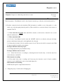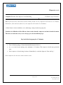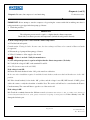
1
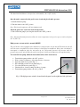
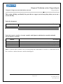
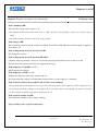
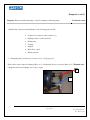
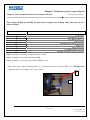
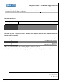
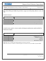
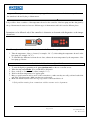
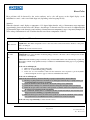
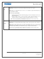
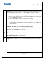
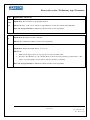
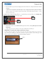
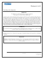
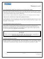
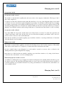
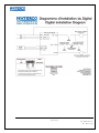
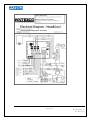
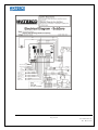
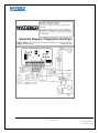
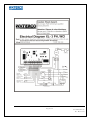
Leader in Heat Pump Pool Heaters
Service Manual 2010
INSTA MANUAL Instructions 2001
The Insta 2001 Pool Heater is designed to work manually (¨On / ¨Off” switch).
Once the unit is connected to the pool’s water circuit and placed under pressure:
1. Start the filtration pump;
2. Turn the switch to the “ON” position.
Note: The fan and compressor will run simultaneously.
When the pool water reaches the desired temperature:
3. Turn off the heat pump by moving the switch to the ¨OFF¨ position;
Note: Integrated thermal protection allows the water temperature in the pool or spa to reach as high as
40 ° C (104 ° F).
High-pressure cut-out switch— manual (RESET)
The pool heater is also equipped with a manual reset, high-pressure cut-out switch. This turns the unit off
when the water circulation in the heat exchanger is interrupted or insufficient. If the water circulation is
interrupted or insufficient when the unit starts up, the refrigeration pressure will increase until the
pressure triggers the switch. When the switch is triggered, the fan and compressor will stop functioning.
To restart the heat pump, follow the instructions below, in the order stated;
Turn the heat pump switch to the “Off” position;
Wait for three (3) minutes to allow the pressure to decrease;
Open the switch access panel (Fig. 1);
Press the high pressure cut-out switch (Fig. 1);
Close the switch access panel (Fig. 1) ;
Check the flow of water coming from the pool pump;
Turn the heat pump switch to the “On” position.
Fig. 1: The high-pressure switch is located inside the panel, on the right-hand side of the unit
Page 2 / 60
ServiceManual2010.doc
Rev. : May 11, 2010
/ Diagnosis
Diagnosis: No power (Nothing is working)
(motor, compressor, unit controllers don’t work)
Preliminary steps /
Consumer
Important: If you have purchased a salt chlorinator, insure that this equipment has been correctly installed on
the heat pump pool heater. If the problem originates from the installation of this equipment, the Waterco
Canada warranty will not apply and you will be responsible for the cost of the service call.
** If the fan blade is not turning, and there is no noise coming from the heat pump pool heater,
we can assume that nothing is working.
1. If you have an Insta Manual model, in addition to following the steps given in the enclosed Manual Control
/ Insta 2001 Model section, make sure the button is in the ¨On¨ position;
2. Make sure the circuit-breaker is not ** defective or closed and/or that the fuses are not burned;
**Only an electrician can verify if the circuit breaker is defective; if this is the case, repairs will not be
covered under the warranty.
3. The pool pump must be functioning (Make sure the water level in your pool is sufficient to ensure that the
water circulation is adequate).
4. The position of the control, or yet, the desired water temperature programmed, must be higher than the
water temperature in the pool; otherwise, change the position of the control, or reprogram. (To ensure
that you understand how to program the heat pump pool heater, consult the ‘Use and Maintenance’ guide.);
5. Make sure the water temperature has not reached the desired level. It is quite normal that the heat pump
pool heater will stop functioning when the water temperature reaches the desired level. The heat pump will
restart when the water temperature goes down. No action is required;
6.
Make sure the water reaches the heat pump pool heater and the pool pump is completely filled to the rim.
Otherwise:
6.1 Fill the pool pump with water, and check to see if the pipes between the pool pump and the pool are watertight (There
should be no air intake);
6.2 Check the skimmer basket and the drain at the bottom of the pool for obstructions;
6.3 Check the filter cartridges for obstructions; (Wash or change the cartridges, as the case may be);
6.4 Insure that the by-pass valves are in the correct positions so that the water flows adequately (Consult the water by-pass
adjustment in the user manual);
6.5 Do a backwash for sand filters (Insure that there is a sufficient amount of sand and verify that it does not have to be
changed. Consult a swimming pool specialist if necessary);
6.6 Make sure the vacuum robot is disconnected so that the water flows freely.
If the problem persists, contact customer service.
Diagnosis (cont’d)
Page 3 / 60
ServiceManual2010.doc
Rev. : May 11, 2010
Diagnosis: No power (Nothing is working)
Technician Section
(motor, compressor, unit control don’t work)
1. In the event the owner has installed a salt chlorinator or any other additional equipment, unplug
everything to insure the owner’s additional equipment is not the cause of the problem;
2. If the problem is related to this equipment, be sure that the owner understands the situation. Because the
problem is not related to the heat pump pool heater, the owner must pay for the service call. Waterco
Canada Inc. will not accept any billing under warranty;
3. If the problem is not related to the additional equipment installed by the owner, check the connections
done by the electrician (This information is available on one of the panels, or inside the cover of the heat
pump electrical panel box);
4. If the connection is not OK; inform and bill the consumer, as the incorrect connection is not covered
under the manufacturer’s warranty. The consumer must notify the installer and/or the electrician
concerned;
5. If the connection is OK, check the continuity between the different parts:
Continuity must always be done in respect to the drawing or electrical diagram which can be found on one of
the panels inside the heat pump electrical panel box.
6.
Change the defective part(s); consult the section: Changing parts.
Page 4 / 60
ServiceManual2010.doc
Rev. : May 11, 2010
Diagnosis Technician section / Suggested Parts
Diagnosis: No power (nothing is working)
Suggested Parts
This section will help you identify the parts that we suggest you to bring along when you are on a
service call duty.
Unit with thermostat:
Quantity
Description
1
1
1
1
1
1
1
1
1
1
Thermostat
Flow switch
Flat washer
Defrost sensor
Time delay
Contactor
Run Capacitor (motor)
Start Assist
Fan motor
Run Capacitor (compressor)
Unit with electronic controller, electronic controller with diagnostic, multi-functions controller and multifunctions Sub-Zero controller.
Quantity
Description
1
Controller
1
Transformer
1
Relay 24V
1
Flow switch
1
(See note 1) Defrost sensor
1
(See note 2)Time delay
1
(See note 2) Controller section / Manual switch
1
Contactor
1
Run capacitor (motor)
1
Start assist
1
Fan motor
1
Run capacitor (compressor)
Note 1: Parts available only for units with an electronic controller.
Note 2: Parts available only with Excellence heater (from 2004 up to September 2009).
Page 5 / 60
ServiceManual2010.doc
Rev. : May 11, 2010
Diagnosis (cont’d)
Diagnosis: Compressor is functioning, but fan does not turn.
Preliminary steps / Consumer
1. Shut the circuit-breaker off for safe handling;
2. Turn the blades of the fan with a rod to see if the motor is jammed;
3. Turn on the circuit breaker and the heat pump pool heater again.
If the problem persists, contact the customer service department.
Page 6 / 60
ServiceManual2010.doc
Rev. : May 11, 2010
Diagnosis (cont’d)
Diagnosis: Compressor is functioning, but fan does not turn
Technician
section
If the heat pump is a ¨Insta Manual¨ model, or the electrical connection goes directly to the electrical panel box;
1. Check the connection done by the electrician. (This information is available on one of the panels, or on the
inside cover of the heat pump electrical panel box.) There should be no connection directly to the contactor at
terminals T1 & T2;
1.1: If the connection is not OK; advise and bill the consumer, as the incorrect connection is not covered
under the manufacturer’s warranty;
1.2: If the connection is OK:
1.2.1: For the ¨ Insta Manuel¨ models, insure the ¨ON/OFF¨ switch is not defective, then press the highpressure switch button in the panel, on the right-hand side of the unit.
1.2.2: Insure the feed relay is 24 volts and the contact is closed. The motor should be connected to the COM
(Common) and N-O (normally open) terminals;
If voltage is OK, but contact stays open:
1.2.3: Change the defective part (Ventilation relay);
If voltage is OK but contact is closed:
1.2.4
Verify if the fan motor is working by connecting the wire from the relay, or from the water flow
switch, directly to terminal L2.
If the fan motor is working:
1.2.5 First check if the relay is working, and if necessary, the electronic control. (Controls available:
electronic control, multifunction control, control with diagnostics)
If the fan motor is not working:
1.2.6 Verify the capacitor output, then the fan motor.
2.
Change the part(s). Consult section: Changing parts.
Page 7 / 60
ServiceManual2010.doc
Rev. : May 11, 2010
Diagnosis Technician section / Suggested parts
Suggested parts
Diagnosis: Compressor stars but fan does not work
This section will help you identify the parts that we suggest you to bring along when you are on a
service call duty
Unit with a thermostat:
Quantity
Description
1
1
Run capacitor(motor)
Fan motor
Unit with electronic controller, electronic controller with diagnosis, multi-function controller and multifunction Sub-Zero controller
Quantity
Description
(See Note 1) Controller
Relay 24V
Run capacitor (motor)
Fan motor
1
1
1
1
Note 1: Controller will be available only for the heat pump with a multi-function controller or a multi-function SubZero controller or with an electronic controller with diagnosis.
Page 8 / 60
ServiceManual2010.doc
Rev. : May 11, 2010
Diagnosis (cont’d)
Diagnosis: Fan turns, but compressor is not functioning
Preliminary steps / Consumer
Note: A protection device (time delay) could be running. In this case, the compressor will restart in 3 to 5 minutes.
Furthermore, if the unit has a defrost cycle, the compressor will restart in 5 to 20 minutes.
1. Check if there is fresh air (Similar to air conditioning) coming from the heat pump fan;
Sometimes it is difficult to tell the difference between noise from the compressor and noise from the fan motor.
Therefore, to avoid unnecessary service charges, proceed to the following steps:
Stay beside the heat pump for 3–5 minutes.
Turn off the heat pump pool heater then immediately turn it back on;
As soon as the fan starts turning, wait a minimum of 3-5 minutes. The compressor should start up after this
time;
If the compressor is functioning, but shuts off immediately, consult the diagnostic “Start and Stop”.
If the compressor does not start, contact customer service.
Page 9 / 60
ServiceManual2010.doc
Rev. : May 11, 2010
Diagnosis (cont’d)
Diagnosis: Fan turns, but compressor is not functioning
Technician section
IMPORTANT: Never attempt to start the compressor by pressing the contact switch before making sure there is
refrigerant in the copper pipes in the heat pump pool heater.
1. Check the pressures:
IMPORTANT
The refrigerant pressure must be equal to or higher than the climate temperature
Check with your charter pressures and temperatures (include the refrigerant in the unit)
A) If the refrigerant pressure is lower than the climate temperature:
A.1 Find the leak and repair it.
Consult section: ¨Testing for leaks¨. In some cases, the heat exchanger will have to be returned to Waterco Canada
for appraisal.
A.2 Restart the pool pump and heat pump pool heater;
A.3 Wait 3-5 minutes to allow supply to the circuit.
If there is no leak – Notify the manufacturer.
B) If the refrigerant pressure is equal to or higher than the climate temperature (No leaks):
B.1 Verify if the voltage is 240V on the terminals L1 and L2.
(Note: The fan motor may work with 120V)
If the voltage is not OK:
B.2 Insure the circuit breaker is in the ¨ON¨ position and is not defective.
In the case where installation requires 2 non-linked circuit breakers, make sure that both breakers are in the ¨ON¨
position.
B.3 If the circuit breaker(s) is/are in the ¨ON¨ position, and the voltage is not OK (120V instead of 240V), please
advise the owner to notify the electrician or installer. Note: The service call will not be covered under the Waterco
Canada warranty. The owner will have to pay the cost of the service call.
If the voltage is OK:
B.4 Check the continuity between the different controls. (Continuity must always be done according to the drawing or
electrical diagram indicated on one of the panels, or inside the heat pump electrical panel box. If the continuity is not OK,
change the defective part.
Page 10 / 60
ServiceManual2010.doc
Rev. : May 11, 2010
Diagnosis (cont’d)
Diagnosis: Fan turns, but compressor is not functioning
Technician section
If the continuity is OK:
B.5 Check the voltage on the contactor coil;
For manual models (knob swings from ¨ON¨ to ¨OFF¨) and for electro-mechanic controls, the circuit voltage is
240V;
For models with an electronic control, the voltage is 24V.
If the voltage is OK:
B.6 Verify if the electrical current reading for terminals T1 and T2 is 240V when the electrical current is supplied to
the contactor coil.
If the reading for the electrical current is not OK:
B.7 Change the contactor;
If the reading for the electrical current is OK (240V):
Check the amperage when the contactor is closed. If the amperage spike (LRA) lasts more than 2 seconds,
B.8 Disconnect the capacitor and verify the output in µF (run cap);
If the output in µF is not OK: (+/- 5%)
B.9 Change the run capacitor
If the output in µF is OK: (+/- 5%)
B.10 Install a hard start assist and do another start test.
B.11 Disconnect the compressor and check the electrical resistors on the compressor’s terminals;
If the electrical resistor to the terminals is nil, or if there is no continuity:
**It is possible that the thermal protection is open. Check the temperature of the compressor. If the compressor is hot,
let it cool and recheck the continuity to the terminals. To cool it down, shut the circuit breaker off and pour cold water
over the compressor until the temperature reads below 90 ° F.
If the electrical resistors are OK:
B.12 Check the continuity of the compressor wiring.
If the problem persists, notify the manufacturer.
Page 11 / 60
ServiceManual2010.doc
Rev. : May 11, 2010
Diagnosis Technician section / Suggested parts
Diagnosis : Fan turns but compressor does not start
Suggested parts
This section will help you identify the parts that we suggest you to bring along when you are on a
service call duty
Unit with thermostat:
Quantity
Description
1
1
1
1
1
Defrost sensor
Time delay
Contactor
Start assist
Run Capacitor (Compressor)
Unit with electronic controller, electronic controller with diagnosis, multi-functions controller and multifunctions Sub-Zero controller
Quantity
Description
1
1
1
1
1
1
Controller
(See note 1)Defrost sensor
(See note 2) Time delay
Contactor
Start assist
Run Capacitor (Compressor)
Note 1: The sensor is necessary and available only if the heat pump as an electronic controller.
Note 2: Time delay is available and necessary only on the Excellence heat pump (from 2004 up to September 2009)
Page 12 / 60
ServiceManual2010.doc
Rev. : May 11, 2010
Diagnosis (cont’d)
Diagnosis: Water around the heat pump, or water leaking from the
Preliminary steps / Consumer
heat pump
In addition to carefully reading about the occurrence of condensation, this is quite normal and clearly explained in
the Installation and Maintenance Guide. Make sure the installation corresponds to the recommendations given by
Waterco Canada Inc.,
To insure that the occurrence of condensation is normal, follow the directions below, starting early in the
morning and continuing for the whole day.
IMPORTANT: Shut the circuit breaker off. The heat pump must not be running during this test:
1. Turn off the pool pump;
2. Open the by-pass valve;
3. Close the water inlet and outlet valve;
4. Restart the pool pump;
5. Once there is no condensation (At the base, and the earth is dry), open the water inlet and outlet valve and close
the by-pass valve. Remember, the heat pump must not be operating; (Circuit breaker is shut off.), only the
pool pump should be running.
Let the water circulate freely and if you notice the water is running inside, instead of outside
the heat pump pool heater, contact customer service.
Page 13 / 60
ServiceManual2010.doc
Rev. : May 11, 2010
Diagnosis (cont’d)
Diagnosis: Water around the heat pump, or water is leaking from the heat pump
Technician section
1 Check if the connections and installation of the following parts are OK:
Compression connector (cable connector ¾);
Exchanger inlet or outlet (canisters);
Sealing ring;
V-clamp;
Adapter;
Water flow control;
Thermostat well.
2. Change the part(s), if necessary. Consult section: “Changing parts”
If the leak is at the compression fittings (Photo no. 1) and that the elbows are in brass (Photo no.2) (Titanium coils).
Change the entire heat exchanger. Do not try to repair.
2
1
.
Page 14 / 60
ServiceManual2010.doc
Rev. : May 11, 2010
Diagnosis Technician section / suggested parts
Diagnosis : Water around the unit of water leaking from the unit
Section Suggested parts
This section will help you identify the parts that we suggest you to bring along when you are on a
service call duty
Quantity
Description
1
30
3
1
3/3
1
2
1
1/1
Flow switch
(See Note 1) Clear Hose
(See Note 2) Fitting 1/8
Canister in/out
(See note 3) Hose fitting / Toric ring
Rubber ring
Cable gland ¾ npt
(See note 2) Thermostat well
(See note 3) Thermostat well / Toric ring
Note 1: Available for all models, except the Sub-Zero model;
Note 2: Available for all models until January 2009;
Note 3: Available for all models from February 2009 up to now.
If the leak is at the compression fittings (Photo no. 1) and that the elbows are in brass (Photo no.2) (Titanium coils).
Change the entire heat exchanger. Do not try to repair.
2
1
Page 15 / 60
ServiceManual2010.doc
Rev. : May 11, 2010
Diagnosis (cont’d)
Diagnosis: Heat pump is functioning, but does not reach the temperature
Preliminary steps /Consumer
programmed or requested. Pump is not heating
Atmospheric conditions should be above 52° F. (11 ° C), and pool water should be above 65 ° F (18 ° C) before
proceeding to the next step.
Make sure the heat pump pool heater is installed according to the recommendations; consult the Use and
Maintenance Guide.
Improper installation may cause a permanent condition, and installation will have to be corrected.
1. Make sure the by-pass valves are in the correct positions to insure sufficient water flow (water circulation), as
insufficient water flow will cause the compressor to shut off.
2. If you have installed a timer, or the heat pump pool heater model is equipped with an integrated timer, be sure it
is programmed to allow the pump to work for a long time in order to reach the desired or programmed
temperature.
We recommend that you use a solar pool cover to conserve the heat of the pool water.
Pools without solar covers lose 2 to 3 times more heat than pools with solar covers.
** If the problem persists, contact customer service; be sure to have the pool dimensions and quantity of water
(In litres or gallons) on hand.
Page 16 / 60
ServiceManual2010.doc
Rev. : May 11, 2010
Diagnosis (cont’d)
Diagnosis: Heat pump is functioning, but does not reach the temperature Preliminary steps/Consumer
programmed or requested. Pump is not heating
You need to make sure that the heat pump is properly programmed. During this little test, the heat pump and the
pool pump will be working continuously.
Analysis Chart
Important: Take the information needed during daytime, before 12h00 for
three consecutive days.
Day 1
Day 2
Day 3
Day 1
Day 2
Day 3
Outside air temperature ………………………………………….............
Climatic conditions outside
(For example: cloudy, sunny or rainy)
Pool water temperature……………………………………………..
**Use pool thermometer
Pool water temperature……………………………………………...
**Write the data given on the swimming pool heat pump controller
Important :Take the information needed 8 hours later than the ones taken
during daytime
Outside air temperature ………………………………………………….
Climatic conditions outside ………………………………………………...
(For example : cloudy, sunny or rainy)
Pool water temperature……………………………………………..
**Use pool thermometer
Pool water temperature……………………………………………...
** Write the data given on the swimming pool heat pump controller
Page 17 / 60
ServiceManual2010.doc
Rev. : May 11, 2010
Diagnosis (cont’d)
Diagnosis: Heat pump is functioning, but does not reach the temperature programmed or
requested. Pump is not heating.
Technician section
Follow the same procedures listed under diagnostic: “Fan turns, but compressor is not functioning.”
Page 18 / 60
ServiceManual2010.doc
Rev. : May 11, 2010
Diagnosis section / Technician / Suggested Parts
Diagnosis: Heat pump is functioning, but does not reach the temperature
programmed or requested. Pump is not heating.
Suggested parts
Unit with a thermostat:
Quantity
Description
1
1
1
1
Defrost sensor
Contactor
Start assist
Run Capacitor (Compressor)
Unit with electronic controller, electronic controller with diagnostic, multi-functions controller and multifunctions Sub-Zero controller.
Quantity
Description
(See note 1) Defrost Sensor
(See note 2) Time delay
Start assist
Run Capacitor (compressor)
1
1
1
1
Note 1: The sensor in available only if the heat pump has an electronic controller
Note 2: Time delay is available only if the heat pump is an Excellence, (from 2004 up to September 2009)
Page 19 / 60
ServiceManual2010.doc
Rev. : May 11, 2010
Diagnosis (cont’d)
Diagnosis: Compressor starts and stops
Preliminary steps/Consumers
It is quite normal for this situation to occur at the beginning of the season, as the water and air temperatures are cold.
Atmospheric conditions above 52 ° F. (11 ° C) and pool water above 65 ° F (18 ° C) should solve this problem.
Otherwise, you will have to wait until conditions are more favourable
1. Recheck the information written out for installation in the Use and Maintenance Guide located in the section
regarding the hydraulic link (diagram). Pay close attention to insure that the connections are correct for the heat
pump pool heater inlet and outlet. An improper installation, such as no air circulation, can cause a permanent
condition and the installation will have to be corrected.
2.
Insure the water reaches the heat pump pool heater and the pool pump is completely filled to the rim.
Otherwise:
2.1 Fill the pool pump with water, and check to see if the pipes between the pool pump and the pool are watertight (There should
be no air intake);
2.2 Check the skimmer basket and the drain at the bottom of the pool for obstructions;
2.3 Check the filter cartridges for obstructions; (Wash or change the cartridges, as the case may be);
2.4 Insure that the by-pass valves are in the correct positions so that the water flows adequately (Consult the water by-pass
adjustment in the user manual);
2.5 Do a backwash for sand filters (Insure there is a sufficient amount of sand and verify if it needs to be changed. Consult a
swimming pool specialist if necessary);
2.6 Make sure the vacuum robot is disconnected so the water flows freely.
IMPORTANT
Make sure the circuit breaker is shut off before cleaning the evaporator.
3. Clean the evaporator (the grill around the heat pump) with a light flow water hose, on and under (avoid using a
pressure hose).
If the problem persists, contact customer service.
Page 20 / 60
ServiceManual2010.doc
Rev. : May 11, 2010
Diagnosis (cont’d)
Diagnosis: Compressor starts and stops
Technician section
IMPORTANT
Never attempt to start the compressor by pressing the contact before making sure there is refrigerant in the
heat pump pool heater copper pipes.
1. Check the pressure
IMPORTANT
The refrigerant pressure must be equal to or higher than the climate temperature.
Do Not hesitate to consult the pressure and temperature chart (be careful with the Freon in the unit)
A)
If the refrigerant pressure is lower than the climate temperature:
A.1 Find the leak and repair it.
Consult section: ¨Testing for leaks¨. In some cases, the heat exchanger will have to be returned to Waterco Canada
for appraisal.
A.2 Restart the pool pump and the heat pump pool heater;
A.3 Wait 3 to 5 minutes to allow feed to the compressor.
If there are no leaks –
Check the capillaries. These should be no obstruction.
Consult the procedures in section: “Checking the Capillaries”.
Note: There will be a significant difference between the high and low pressures. For example, high will indicate
300PSI while low will indicate 40PSI.
Page 21 / 60
ServiceManual2010.doc
Rev. : May 11, 2010
Diagnosis (cont’d)
Diagnosis: Compressor starts and stops
Technician section
The following parts can also cause problems if they open before the protection value stated below:
Part Description
Defrost Control
High-Pressure Control
Protection Value
Temperature above 23 ° F (-5 ° C)
Pressure below 425 PSIG
or before 2007 at 350 PSIG
Timer
For all heat pump pool heaters SE (with an electro-mechanic
control) or Excellence, the delay is 3 minutes before the contact
shuts off.
** A defect occurs if the contact re-opens before the electrical
current is cut.
Low-Pressure Control
Pressure above 25 PSIG
or before 2006, 35 PSIG
Page 22 / 60
ServiceManual2010.doc
Rev. : May 11, 2010
Diagnosis Section Technician / Suggested parts
Diagnosis : The heat pump starts and stops/ Compressor starts and stops
Suggested Parts
This section will help you identify the parts that we suggest you to bring along when on a service call
duty.
Unit with a thermostat:
Quantity
Description
1
1
1
1
1
Defrost sensor
Time delay
Contactor
Start Assist
Run capacitor compressor
Unit with electronic controller, electronic controller with diagnostics multi-functions controller and Sub-Zero
multi functions controller.
Quantity
Description
1
1
1
1
1
1
Controller
(See note 1) Defrost sensor
(See note 2) Time delay
Contactor
Start assist
Run capacitor compressor
Note 1: the sensor is available only if the heat pump has an electronic controller;
Note 2: The time delay is available only if the heat pump is an excellence model. (From 2004 to September 2009)
Page 23 / 60
ServiceManual2010.doc
Rev. : May 11, 2010
Diagnosis (cont’d)
Diagnosis: Heat pump is frozen (Ice or frost has formed on the
Preliminary steps /Consumer
pump)
** It is quite normal that frost will form when the outdoor temperature is cool, particularly at the beginning of
the season. Don’t be concerned. This situation is temporary.
IMPORANT:
Make sure the circuit breaker is shut off before cleaning the evaporator.
1. Clean the evaporator (The grill around the heat pump pool heater) with a light-jet water hose on or under (Avoid
using a pressure hose); and let the evaporator dry before starting the heater again to avoid repeating the situation and
go on with the next step.
2. Insure that the installation respects the recommendations given by Waterco Canada Inc. An improper installation
may cause a permanent condition and installation will have to be corrected;
3. Check if the fan is STILL turning (Blades should turn) while the compressor is functioning;
4. If the fan does not turn and the compressor is functioning; notify customer service.
** If Waterco Canada requires the services of a specialized technician, the owner of the heat pump pool heater will
have to stop the unit completely before the technician arrives.
If there is no change:
** For 150BTU units manufactured between January 2007, and July 2007: Consult a specialized technician
(Technical Data: Heat Pump 150 BTU)
Page 24 / 60
ServiceManual2010.doc
Rev. : May 11, 2010
Diagnosis (cont’d)
Diagnosis: Heat pump is frozen (Ice or frost has formed)
Technician section
IMPORTANT: For all units manufactured between January 2007, and July 2007: it is important to consult and
follow the procedures in Technical Data under “Heat Pump 150BTU”, before following the steps below. Technical
Data Positioning of the defrost probe on the Sub-Zero and/or Positioning of the defrost probe 105/125/150.
IMPORTANT
Never attempt to start the compressor by pressing on the contactor contact before insuring there is refrigerant in
the heat pump pool heater copper pipes.
1. Check the pressure
IMPORTANT
The refrigerant pressure must be equal to or higher than the climate temperature.
Check with your charter pressures and temperatures (note the condenser included in the unit)
A) If the refrigerant pressure is lower than the climate temperature:
A.1 Find the leak and repair it.
Consult section ¨Testing for leaks ¨, as in certain cases the heat exchanger will have to be returned to Waterco
Canada for appraisal.
A.2 Restart the pool pump and heat pump pool heater;
A.3 Wait 3-5 minutes so the electrical current is supplied to the circuit.
If there is no leak – Notify the manufacturer.
B) When the heat pump does not work, and if the refrigerant pressure is equal to or higher than the climate
temperature.
B.1 Check the condition of the capillaries; ** Consult the procedures in section ¨Checking the capillariesIf the capillaries are OK:
B.2 Check the condition of the expansion valve: Modify the expansion valve adjustment to see if the pressures vary.
If there is no change, the valve will have to be replaced.
Page 25 / 60
ServiceManual2010.doc
Rev. : May 11, 2010
Diagnosis (cont’d)
Diagnosis: Heat pump is frozen (Ice or frost has formed)
Technician section
If the expansion valve is OK:
B.2 Check the defrost control: This control could cause a problem if it opens before the protection value at a
temperature above 23 ° F (-5 ° C)
3.
Restart the heat pump pool heater and check to see if it is working.
If the problem persists:
4. Check if the fan is still turning (Blades should be turning) while the compressor is functioning;
5. If the fan is not running, and the compressor is functioning, the ventilation motor overheats and may stop
intermittently. Change the fan motor. Consult section ¨Changing parts ¨.
Page 26 / 60
ServiceManual2010.doc
Rev. : May 11, 2010
Diagnosis / Technician / Suggested parts
Diagnosis : Heat pump has frozen (ice or frost has formed)
Suggested parts
This section will help you identify the parts that we suggest you to bring along when on a service call duty.
Unit with thermostat:
Quantity
Description
1
1
1
Defrost sensor
Run capacitor (motor)
Fan motor
Unit with electronic controller, electronic controller with diagnostic, multi-functions controller and multifunctions Sub-Zero controller.
Quantity
Description
1
1
1
1
Relay 24V
(See note 1) Defrost sensor
Run capacitor (motor)
Fan motor
Note 1: The sensor is available only if the heat pump has an electronic controller.
Page 27 / 60
ServiceManual2010.doc
Rev. : May 11, 2010
Diagnosis (cont’d)
Diagnosis: Circuit breaker trips
Preliminary steps / Consumer
Important: If you have purchased a remote control (or other equipment), make sure this equipment was properly
installed. If the problem originates from the installation of this equipment, Waterco Canada’s warranty will not
apply and you will have to pay the cost of the service call.
1. Check if the amperage of the circuit breaker AND the electrical wiring are OK. Consult the table below.
Circuit Breaker: May vary, according to the model of the heat pump pool heater, between 30 and 50 amps.
Electrical Wiring: May vary between 12 AWG and 6 AWG.
A) If the circuit breaker and/or the electrical wiring are not OK.
A.1 Notify your installer or electrician to correct this problem, as this is not covered under the warranty.
B) If the circuit breaker and electrical wiring are OK.
B.1 Make sure the drains, located on each side of the base of the heat pump pool heater are not obstructed;
Model
Feed
Circuit Breaker
Electrical wire rating
(AWG)
25 BTU, 35 BTU ET 45 BTU
220
20
12
55 BTU
220
30
10
70, 75 BTU
220
30
10
80, 85, 90 BTU
220
40
8
100,105 BTU
220
40
8
120,125 BTU
220
50
6
140,150 BTU
220
50
6
Note: The above-mentioned information is for a total rating of 100 feet, maximum. If over 100 feet, you will have to
increase the electrical wiring feed.
If the problem persists, contact customer service.
Page 28 / 60
ServiceManual2010.doc
Rev. : May 11, 2010
Diagnosis (cont’d)
Diagnosis: Circuit breaker trips
Technician section
1. Make sure the heat pump pool heater and pool pump are functioning;
2. Determine if the circuit breaker trips when the fan motor starts or when the compressor starts;
A) To determine if the circuit breaker trips when the fan motor starts:
A.1 Shut the circuit breaker off;
A.2 Disconnect the fan motor;
A.3 Turn the circuit breaker back on;
IMPORTANT: The circuit breaker will not necessarily trip when there is no heat demand.
To create a heat demand, modify the position of the control or programmer to start the heat pump pool heater
again. (Creating a heat demand) (Be sure you understand how to program the heat pump pool heater by consulting
the Use and Maintenance Guide);
If the circuit breaker does not trip:
B.1 Change the fan motor and/or the run capacitor;
If the circuit breaker continues to trip:
B.2 Check the connections from the heat pump pool heater to the junction box to see if the connections were done
correctly (loose wires);
B.3 Disconnect the heat pump pool heater supply to see if there isn’t a short circuit between the wires from the
circuit breaker to the heat pump;
B.4 Check to see if the 240V voltage reaches the heat pump;
If the voltage is OK:
B.5 Check the continuity on the feed wire that links the junction box to the contactor;
If the continuity is not OK:
B.6 Change the feed wire on the heat pump pool heater, restart the heat pump pool heater, and check to see if it is
working;
Page 29 / 60
ServiceManual2010.doc
Rev. : May 11, 2010
Diagnosis (cont’d)
Diagnosis: Circuit breaker trips
Technician section
If the continuity is OK:
Check if the contactor electrical current reading is 240V on terminals T1 and T2, when there is a feed to the
contactor coil;
B.7 Check the condition of the contactor and change it if necessary;
If the contactor is OK:
B.8 Check the electrical resistor between the different controls and change the part if defective.
If the problem persists:
If the electrical current reading is OK (240V):
B.9 Check the amperage when the contactor closes. If the amperage spike (LRA) lasts more than 2 seconds,
B.10 Disconnect the capacitor and check the capacity in µF (run cap) ;
If the capacity in µF is not OK: (+/- 5%)
B.11 Change the run capacitor
If the capacity in µF is OK: (+/- 5%)
B.12 Install a Hard Start Assist and do another start test.
B.13 Disconnect the compressor and check the electrical resistors on the compressor terminals;
If the electrical resistor to the terminal is infinite, or if there is no continuity:
B.14 The thermal protection could possibly be open. Be sure to check the temperature of the compressor. If the
compressor is very hot, cool it down and recheck the continuity at the terminals. To cool down the compressor, shut
the compressor off and pour cold water over it until the temperature reads below 90 ° F. (32 ° C)
If the electrical resistors are OK:
B.9 Check the continuity of the feed wires from the compressor.
If the problem persists, notify the manufacturer.
Page 30 / 60
ServiceManual2010.doc
Rev. : May 11, 2010
Diagnosis section / Technician /Suggested parts
Diagnosis : Circuit breaker trips
Suggested parts
This section will help you to identify to pieces we suggest you to bring along when you are on a service
call duty.
Unit with thermostat:
Quantity
Description
1
1
1
1
1
1
1
1
1
Thermostat
Flow switch
Flat washer
Defrost sensor
Contactor
Run capacitor (motor)
Start assist
Fan motor
Run capacitor (compressor)
Unit with electronic controller, electronic controller with diagnostics, multi-functions controller and Sub-Zero
multi-functions controller:
Quantity
Description
1
1
1
1
1
1
1
1
Controller
Transformer
(See note 1) Defrost sensor
Contactor
Run capacitor (motor)
Start assist
Fan motor
Run capacitor (compressor)
Note 1: The sensor is available only with the electronic controller
Page 31 / 60
ServiceManual2010.doc
Rev. : May 11, 2010
Diagnosis section / Consumer / Preliminary steps
Diagnosis : The heat pump is noisy
Preliminary steps/ Consumer
1. Make sure the heat pump is plumbed and on a solid base to avoid any risks of vibrations.
2. Make sure noise is coming from the unit and not from pool equipment. For example a by-pass system or a
pool pump.
If the problem is persistent, contact our customer service department.
An improper installation might cause this situation permanently and the installation would need to be
corrected.
Page 32 / 60
ServiceManual2010.doc
Rev. : May 11, 2010
Diagnosis section / Technician section
Diagnosis : The heat pump is noisy
Technician section
Verify where the noise comes from and change the part if necessary. A bad installation might permanently cause this
situation. The installation must be corrected. This situation is not honoured by warranty. Do not hesitate to consult the
use and care guide for further information.
Page 33 / 60
ServiceManual2010.doc
Rev. : May 11, 2010
Diagnosis section / Technician / Suggested parts
Diagnosis : The heat pump is noisy
Suggested Parts
This section will help you identify the parts that we suggest you to bring along when on a service call duty
Quantity
Description
(See note 1) Transformer
Contactor
Run capacitor (motor)
Start assist
Fan Blade
Fan motor
Run capacitor (compressor)
1
1
1
1
1
1
1
Note 1: The transformer is not available for the heat pumps that have an electro-mechanical thermostat.
Page 34 / 60
ServiceManual2010.doc
Rev. : May 11, 2010
.
Diagnosis: The temperature showed by the heat pump pool heater is not
Preliminary steps / Consumer
the same that is showed by the pool thermometer.
It is possible to have a variation of the temperature showed on the controller of the heat pump and the data given by
the pool thermometer because we have two different types of thermometers and both located at different places.
Instructions to be followed only if the controller is electronic or electronic with diagnostics as the images
shown here:
CEL.
FAR.
°C/°F
C/F
ON/OFF
°C
°F
I/O
To calibrate, please follow this procedure (as shown in the Use and Care guide):
1. Take the temperature of the pool water (for example : 26 ° C); After taking the temperature showed on the
heat pump (for example : 24 ° C);
2. To determine the difference between the two data, subtract the water temperature by the temperature of the
heat pump pool heater.
So, 26 - 24 = 2 ° C; we have to adjust of 2 ° C
To enter the digital programming mode, press simultaneously on the two controller arrows;
When the temperature flashes, press on ON-OFF or I/O button
Press on the up or down arrows to adjust (example: 2 ° C).
Wait for the water temperature to be appear again;
Bring a special attention and be aware of the connections to make sure they are well positioned at the inlet
and outlet of the heat pump. (Make sure they are not inverted) ;
8. Make sure that the by-bass valves are in good positions so the water debit is ok
9.
** If the problem remains, please communicate with the customer service department.
3.
4.
5.
6.
7.
Page 35 / 60
ServiceManual2010.doc
Rev. : May 11, 2010
Diagnosis: The temperature showed by the heat pump pool heater is not
Technician section
the same that is showed by the pool thermometer.
Depending on the heat pump pool heater model, if the problem remains even after these preliminary steps,
change the controller or maybe the temperature probe.
Page 36 / 60
ServiceManual2010.doc
Rev. : May 11, 2010
Diagnosis Section/ Technician / Suggested Parts
Diagnosis: The temperature on the heat pump is not the same as the
Suggested Parts
temperature you read on the pool thermometer.
This section will help you identify the parts that we suggest you to bring along when on a service call duty
Quantity
1
1
Description
(See note 1) sensor probe or replacement probe
Controller
Note 1: The replacement probe or temperature sensor probe is available only for units with a multi-functions
electronic controller, a multi-functions Sub-Zero controller or an electronic controller with diagnostic.
Page 37 / 60
ServiceManual2010.doc
Rev. : May 11, 2010
Error Codes
Most problems will be detected by the service analyzer, and a code will appear on the digital display on the
multifunction control, or the control with diagnostic (depending on the heat pump model).
Attention:
When the electronic control displays a temperature of 32 degrees higher than the real pool thermometer water temperature
(approximately), please refer the service call to Waterco; since this type of electronic control does not need to be calibrated and the
gap between the degree on the electronic control and the pool thermometer water temperature is way too important. (Example: Pool
water on the pool thermometer is at 85 º F and the electronic control shows a temperature of 210 º F.)
Code
Significance / What to do
dPd, oC2, Sc2
Significance: The intake temperature sensor is the cause. The connection should be checked, or the probe
has to be changed.
What to do: Contact customer service.
FLo, FL3
Significance: No water circulation in the heat pump pool heater or the water control switch pressure should
be adjusted, or is defective.
nFL
What to do: If the circulation pump is connected to the pool heater. Make sure the control that runs the pool pump and
heat pump pool heater was programmed correctly. Consult the Use and Maintenance Guide, page 17, for programming
the control.
If the code is still displayed:
Make sure the pool pump is functioning (ON) ;
Press ¨set¨ to restart the heat pump pool heater;
In the case of a new installation, make sure the instructions were respected as per the hydraulic
connection diagram, shown on page 8, in the Use and Maintenance Guide;
If the code is still displayed:
Make sure the water reaches the pool heater and that the pool pump is completely filled to the rim. Otherwise :
Fill the pool pump with water, and check to see if the pipes between the pool pump and the pool
are watertight (There should be no air intake);
Check the skimmer basket and the drain at the bottom of the pool for obstructions;
Check the filter cartridges for obstructions (Wash or change the cartridges, as the case may be);
Insure the by-pass valves are in the correct positions so that the water flows adequately (Consult
the water by-pass adjustment in the user manual).
Do a backwash. (Insure there is a sufficient amount of sand and verify it does not have to be
changed. Consult a swimming pool specialist if necessary);
Make sure the by-pass valves are in the correct positions. (Consult the adjustment of the water bypass system in the Use and Maintenance Guide) so that the flow of water is adequate;
If the code stays on permanently; Contact customer service.
Page 38 / 60
ServiceManual2010.doc
Rev. : May 11, 2010
Error Code (cont’d)
FS
Significance: Normal defrost cycle. The fan is turning, but the compressor has stopped.
DEF
What to do: At cool temperatures below or near 12 ° C, ice formation is quite normal. The defrost cycle
starts up, and this is essential.
If the code stays on permanently:
Clean the evaporator (The grill around the heat pump pool heater) with a light-jet water hose (avoid
using a pressure hose);
Recheck installation (page 7) in the section under ¨Locating¨. Improper installation, e.g. no air
circulation could lead to a permanent condition and installation will have to be corrected.
If the code stays on permanently, and installation is not the cause: Contact customer service.
Significance: Low refrigerant fluid in the heat pump pool heater or the low-pressure control is defective.
LP, LP3
What to do: It is quite normal for this code to appear at the beginning of the season, as the water and air
temperatures are cold. Weather conditions above 52 ° F. (11° C) and pool water above 65 ° F (18 ° C), will
eliminate this situation. Otherwise, you should wait until these conditions are more favourable.
If the code stays on permanently and the conditions are favourable: Contact the customer service.
Page 39 / 60
ServiceManual2010.doc
Rev. : May 11, 2010
Error Code (cont’d)
HP,
HP3
Significance: Low water circulation in the unit or the high-pressure control is defective. The HP code is displayed 3
times; this will cause the heat pump pool heater to shut off. Afterward, the HP3 code will appear permanently.
Note: The pool pump will stop functioning only if the internal time delay of the heat pump pool heater is working.
Insure the water reaches the heat pump pool heater and the pool pump is completely filled to the rim. Otherwise:
Fill the pool pump with water, and check to see if the pipes between the pool pump and the pool are
watertight. (There should be no air intake)
Check the skimmer basket and the drain at the bottom of the pool for obstructions;
Check the filter cartridges for obstructions (Wash or change the cartridges);
Insure that the by-pass valves are in the correct positions so that the water flows adequately (Consult the
water by-pass adjustment in the Use and Maintenance Guide);
Do a backwash. Insure the vacuum robot is disconnected so that the water flow is not reduced. (Insure there
is a sufficient amount of sand and verify that it does not have to be changed. Refer to a swimming pool
specialist, if necessary);
IMPORTANT: Make sure the circuit breaker is OFF before cleaning the evaporator.
Clean the evaporator (The grill around the heat pump pool heater) with a light-jet water hose on and under
(avoid using a pressure hose).
If the HP3 code stays on permanently: Contact customer service.
OFF
Significance: The desired level of the temperature programmed is below 60 ° F (15 ° C)
What to do: Reprogram the multifunction electronic control;
If the code stays on permanently: Contact the customer service;
PSD,
oC1 &
Significance: The water temperature sensor is the cause (Connection should be checked or the sensor should be
changed.
Sc1
What to do: Contact customer service.
Page 40 / 60
ServiceManual2010.doc
Rev. : May 11, 2010
Error codes section / Preliminary steps/ Consumers
Code
PLE &
CSE
Signification / What to do
Signification: The controller is not programmed anymore.
What to do : Press on the ‘’select’’ button for approximately 4 seconds, the controller will reinitialized
If the code stays permanently: Communicate with the customer service department.
Spi
Signification: The digital controller is defective.
What to do: Communicate with the customer service department.
Signification: Temperature higher than 45 ° C (113 ° F).
ot
What to do :
1.
Make sure the bypass valves are in good position so the water debit is OK ;
2.
Proceed to the calibration of your controller (Refer to the use and care guide the procedure titled is ‘’The
degree of your heat pump is not the same as wanted or the unit is not heating)
If the code stays permanently: Communicate with the customer service department.
Page 41 / 60
ServiceManual2010.doc
Rev. : May 11, 2010
Error codes section / Technician / Suggested parts
This section will help you identify the suggested parts we recommend you to bring along while on a
service call duty.
Most of the problems will be detected by the service analyzer and a code will appear on the digital controller depending
on the model of your heat pump pool heater.
OFF
Signification : The temperature level desired is lower than 60 ° F (15 ° C)
Suggested pieces : Electronic controller with diagnostic
**Important: Be aware of the technical report named: Changing the electronically controller with
diagnostics.
PSD, oC1 Sc1
PO & Pc
Signification : The water temperature probe is in cause (connections to be checked or probe to be change)
Suggested pieces : Defrost and temperature probe or temperature probe
**Important :Be aware of the technical report named: Change of the probe and electronic controller with
diagnostics
PLE & CSE
Signification : The controller is not programmed anymore
Suggested pieces: Multi-functions controller
Spi
Signification : The digital controller is defect
Suggested pieces : Multi-functions controller
ot
Signification : Water temperature higher than 45 ° C (113 ° F)
Suggested pieces : Electronic controller with diagnostics
**Important :Be aware of the technical report named: Change of the probe and electronic controller with
diagnosis
Page 42 / 60
ServiceManual2010.doc
Rev. : May 11, 2010
Testing for leaks
1. Be sure that when you press the access high pressure valve, the leak is not coming from the inside of the heat
exchanger;
** If the water exits from the system and/or there is noise coming from the inside of the heat exchanger,
inform the customer of the situation. Consult Technical Data “Flooded Heat Pump Pool Heater ¨ to know
what action must be taken.
If leaking from the compression fittings, (Photo no. 1) and the elbows are in brass (Photo no.2) (titanium coils).
Change the entire heat exchanger... Do not try to repair.
2
1
2. Pressurize the system to at least 300 PSI with Nitrogen and test all the soldering with soap or an electronic
leak detector.
** Note: Using an electronic leak detector will require additional Freon and Nitrogen
IMPORTANT – For models with a titanium coil in the heat exchanger:
A leakage of Freon may appear on the adapter between the copper pipes and the titanium coil, as shown below
(fig. 1). This leak is normally very small, and you will have to pay close attention to find it. This type of leak
cannot be repaired, and you will have to change the heat exchanger completely.
Fig. 1
Page 43 / 60
ServiceManual2010.doc
Rev. : May 11, 2010
Testing for leaks (cont’d)
3. Once you have located the leak, repair it, and be sure to write this information on the service bill;
4. Switch the heat pump pool heater to vacuum;
5. Refill the refrigerant as indicated on the data plate on the heat pump pool heater. If this information is
unreadable, consult the parts list to know the exact charge to add;
If there is no leak found, notify the manufacturer
Page 44 / 60
ServiceManual2010.doc
Rev. : May 11, 2010
Changing Parts
WARNING
ALWAYS SHUT OFF THE CIRCUIT BREAKER BEFORE OPENING THE
ELECTRICAL CONTROL PANEL
ON/OFF switch (Insta Manual)
Disconnect one wire at a time from the defective switch and connect it onto the new switch in the same order (the
position of the wires must absolutely be respected). Once completed, remove the defective switch and install the new
one. Check to see if it works.
ON/OFF switch (EXCELLENCE)
Consult the procedures under Technical Data “Changing the EXCELLENCE ON/OFF switch”.
Defrost Sensor
This sensor, usually called “Distat” is attached to the compressor induction tube (The larger of the 2 tubes connected
to the compressor). These wires are normally brown or black and the defrost sensor is insulated (Armaflex). Cut the
brown or black wires inside the electrical control panel, cut the compression fitting holding the switch. Remove the
defrost sensor. Install the new part, making sure the contact on the induction tube closes, and is well insulated.
Reconnect the wires (the position of the wires is not important) and check to see if it works.
Compressor Contactor
IMPORTANT
Insure the contactor coil and the power correspond to the replacement part
Disconnect one wire at a time from the defective contactor and connect it to the new one in the same order. Once
completed, remove the defective contactor and install the new one. Check to see if it works.
Electronic Control 240V (older version, 2003 and before)
Consult Technical Data – “Steps for replacing the Digital ¨Full Gauge¨.
Electronic Control 24V and 12V (Multifunction control)
The easiest way to replace this control is to insert one wire at a time from the new control into the hole of the
electrical control panel. Once the wire is inside, cut the same coloured wire on the defective control, connect the new
wire and remove the defective control wire. Repeat this operation until all the wires are connected. Remove the
defective digital control and install the new one. Check the water temperature sensor to see if it is properly installed in
the chamber on the heat exchanger, and that there is always heat conductor oil (vegetable oil) present in the chamber.
Add silicon to close the chamber opening. Check to see if it is working.
Page 45 / 60
ServiceManual2010.doc
Rev. : May 11, 2010
Changing parts (cont’d)
Electronic Multifunction Control (Pool/Spa)
The easiest way to replace this control is to cut the wires on the defective control while leaving one or two inches of
wire, so you can match the colour of the wires on the new control. Remove the wire harness from the defective
control and unscrew the nuts that hold these wires to the electrical panel box. Insert the new wire harness through the
same hole and screw the nut to fasten it to the electrical panel box. Connect each wire to the same colour wire. Once
this is done, make sure the water temperature sensor is installed correctly into the chamber on the heat exchanger and
that there is always heat conductor oil (vegetable oil) present in the chamber.
Add silicon to close the chamber. Then, remove the defrost sensor attached to the intake tube at the evaporator outlet
(the larger of the 2 tubes connected to the compressor). The sensor is insulated (Armaflex). Install and insulate the
new sensor. Check to see if it is working.
IMPORTANT: The sensor for the heat exchanger chamber is equipped with a red ribbon for quick identification
and to insure that the right part is installed.
Control with diagnostic
Consult the procedures included in Technical Data under “Changing the electronic control with diagnostic.
Water leakage in the compression adaptors (cable connectors ¾)
The compression fitting is located at the extremity of the heat exchanger where there are 2 refrigerant tubes. In most
cases, you will be able to stop the leak by tightening the compression fittings by hand; otherwise, change them.
To replace the compression fitting: Open the top panel, save the refrigerant, cut the copper pipes at the elbows on
the side of the heat exchanger. This will prevent the compression fitting from overheating when you solder the copper
pipes. Disconnect the tubing from the pool, unscrew the 8 screws around the water inlet and outlet (4 on each side) or
the two holding clamps, and remove the heat exchanger.
Unscrew the compression fitting. Add silicon to the threads of the new fitting before putting it back into place.
Replace the heat exchanger, install the copper connections to connect the copper pipes and screw the 8 screws around
the water inlet and outlet or the two holding clamps. Before recharging the refrigerant, connect the pool tubing and
start the pool pump to check for leaks. If possible, circulate the Nitrogen in the system before soldering the copper
piping. Vacuum, recharge and check to see if it working.
Page 46 / 60
ServiceManual2010.doc
Rev. : May 11, 2010
Changing parts (cont’d)
Water leakage at the exchanger inlet
IMPORTANT
To simplify access to the heat pump parts, we suggest you unscrew
the top panel to avoid access by the ventilation grill
Open the top panel, save the refrigerant, cut the copper pipes at the elbows near the compression fitting. Disconnect
the tubing; unscrew the 8 screws around the water inlet and outlet (4 on each side) or the two holding clamps. Remove
the soldering around the copper pipes that are connected to the exchanger, remove the defective heat exchanger.
Remove the compression fitting that is holding the 2 sections of the exchanger together. Remove the water outlet
section with the rubber sealing ring and set aside. Unscrew and remove the compression fitting, then take out the heat
exchanger tube. Place the exchanger tube into the new water inlet and tighten the compression fitting. Add silicon to
the sealing ring on the new exchanger. Change the plastic extrusions in the exchanger before putting it back in place.
Make sure the alignment is perfect before replacing the compressor fitting. Tighten the clamp, put the exchanger back
in place and screw the 8 screws that hold the exchanger in place, or the two holding clamps.
IMPORTANT:
To insure that the exchanger is not leaking; verify by connecting the by-pass system and start the pool pump. It will be
possible to check for water leaks right away, before soldering.
Install the connections to be soldered to the copper pipes. Circulate the Nitrogen in the system before soldering the
copper pipes.
IMPORTANT
Always use a heat absorbent paste or run water slowly over the copper pipes just in front of the compression
fitting before soldering. This will prevent the fitting from overheating. Evacuate the air, recharge, and check to
see if it is working.
Page 47 / 60
ServiceManual2010.doc
Rev. : May 11, 2010
Changing parts (cont’d)
Water leaking from the exchanger outlet (where there are no refrigerant tubes exiting)
Remove the top panel of the unit; unscrew the 8 screws (4 at the water inlet and 4 at the water outlet), or the two
holding clamps. Slowly lift the section opposite the refrigerant tubes and remove the compression fitting holding the 6
sections of the heat exchanger together, or the two holding clamps.
Remove the defective exchanger with the rubber sealing ring. Add silicon to the sealing ring on the new exchanger.
Change the plastic extrusions in the exchanger before putting it back in place.
Insure the alignment is perfect before putting the compression fitting back. Tighten the clamp and screw the 8 screws
that hold the exchanger, or the two holding clamps. Connect the water connections and start the pool pump to test the
ring. Check to see if it is working.
Water leaking from the transparent plastic tube (1/8”)
There are 2 tubes connected to the heat exchanger on each heat pump model. One tube is connected from the
heat pump to a flow switch and the other is connected between the top of the heat exchanger and the water outlet.
These tubes may leak simply because they came loose from their connectors. If this is the case, simply cut the tube
about 3/16¨ and replace the tube. If the tube is cracked, change it.
IMPORTANT
The flow switch is not adjustable on some of the models, and it is black in colour, we suggest that you
always add a clamp nut so that it will not come off again.
Water flow switch (Water flow control)
This part is connected to a transparent plastic tube, with an inside diameter of 1/8”, and is attached to the heat
exchanger. Stop the pool pump, disconnect the wires, disconnect the plastic tube and unscrew the nut holding the
electrical panel box switch. Replace the switch; connect the wires, the plastic tube, and check if it is working.
Page 48 / 60
ServiceManual2010.doc
Rev. : May 11, 2010
Changing parts (cont’d)
Low-pressure switch
Low-pressure switch, screwed:
This switch is connected with a capillary tube and access valve to the compressor intake tube. (The larger of the 2
tubes on the compressor).
To replace it, cut the wires and unscrew this switch. Be careful not to lose any of the refrigerant charge, as the switch
is screwed to an access valve that stops the refrigerant from escaping. You will hear a small amount of gas escaping,
but continue to unscrew the screws quickly and the leak will stop as soon as the low-pressure switch is removed. The
same thing will happen when you screw the new switch in. Make sure the new low-pressure switch does not leak, by
applying soap around the connection and/or using a leak detector. Connect the wires then check to see if it is working.
Low-pressure switch, soldered:
Note: Since 2006, all low-pressure switches have been soldered and not screwed. To reduce the repair time, the
soldered low-pressure control stays in place; this does not affect the heat pump’s performance. Add a new lowpressure control to the access valve on the intake tube.
Insure the new switch does not leak by applying soap around the connection or by using a leak detector. Connect the
wires, then check to see if it working.
High-pressure switch
This switch is connected with a capillary to the tube and a discharge access valve from the compressor. (The smaller
of the 2 tubes on the compressor). To replace it, you must cut the wires and unscrew the switch.
Be sure to check if there is any refrigerant loss, as the switch is screwed to an access valve or soldered to the
discharge tube that stops the refrigerant from escaping.
Insure there is no leak from the new switch by applying soap around the connection, or by using a leak detector.
Connect the wires, then check to see if it is working properly.
When the high-pressure switch is screwed:
You will hear a small amount of gas escaping, but continue screwing the screws quickly and the leak will stop once
the switch is removed. The same thing will happen when you screw on the new switch. Insure the new switch does
not leak by applying soap around the connection or by using your leak detector. Connect the wires, then check to see
if it is working correctly.
Changing Parts (cont’d)
Page 49 / 60
ServiceManual2010.doc
Rev. : May 11, 2010
When the high-pressure switch is soldered:
Note: Since 2006, all high-pressure switches have been soldered and not screwed. To reduce the repair time, the
soldered high-pressure control (defective) will stay in place; this has no effect on the heat pump’s performance. Screw
the new high-pressure control onto the access valve on the exhaust tube. Insure the new switch does not leak by
applying soap around the connection, or by using a leak detector. Connect the wires, then check to see if it is working.
Pressure gauge:
Consult the Technical Data under: Deleting the pressure gauge.
Capillary Kit
Save the refrigerant. Remove the soldering from the refrigerant dispenser, the capillaries, and remove the defective
capillary kit. Put the new kit in place, (careful not to separate one of the capillaries from the refrigerant dispenser
while soldering). Evacuate the system. Recharge with Freon. Carefully read the information indicated on the
nameplate (data plate) and/or on the parts list.
Time Delay
Note: For some heat pump or pool heater models, the timer is integrated in the electronic control. This 3-5 minute
time delay is connected between the high-pressure switch and the compressor contactor coil. If the timer is defective,
simply cut the wires, remove the timer and change it. Connect the wires (the position of the wires is not important),
then check to see if it is working.
Ventilation Motor
Disconnect the wires in the electrical panel box marking their positions. Remove the screws holding
the ventilation grill. Lift the grill to remove the blades and the wires from the wire cover. Remove the motor from the
grill and install the new motor. Check to see if it is working.
Ventilation Motor Relay
Disconnect one wire at a time from the defective relay, and connect it to the new one, in the same order. Once this is
done, remove the defective relay and install the new one. Check to see if it is working.
Page 50 / 60
ServiceManual2010.doc
Rev. : May 11, 2010
Changing parts (cont’d)
Sensor with multifunction control and control with diagnostic
Consult the procedures included in the Technical Data under changing electronic control sensor with diagnostic and
multifunction.
Electro-mechanical Thermostat
Remove the defective thermostat and install the new one (The position of the wires is not important). Insure the water
temperature sensor (Bulb) is installed correctly in the chamber located on the heat exchanger, and that there is always
heat conductor oil (vegetable oil) present in the chamber. Add silicon to close the chamber opening. Check to see if it
is working.
Expansion Valve
Save the refrigerant. Remove the soldering from the expansion valve and install the new valve.
Important: Before soldering the new expansion valve, cover it completely with a water-soaked cloth so it does not get
damaged. Evacuate the system. Recharge with Freon. Do not hesitate to consult the information clearly indicated on
the nameplate (data plate) and/or on the parts list.
Page 51 / 60
ServiceManual2010.doc
Rev. : May 11, 2010
Procedure / checking the capillaries
For this procedure, change the position of the by-pass valves to keep the water from reaching the heat
pump pool heater.
Remove the water in the heat exchanger;
Short-circuit the water flow switch (Never short-circuit the high pressure switch);
Start the compressor by hosing down ALL the capillaries (near the distributor);
The temperature of the capillaries will increase until the compressor turns off due to the high pressure;
**All the capillaries should be the same temperature. If there is one that stays cold, change all the
capillaries.
Page 52 / 60
ServiceManual2010.doc
Rev. : May 11, 2010
Page 53 / 60
ServiceManual2010.doc
Rev. : May 11, 2010
Page 54 / 60
ServiceManual2010.doc
Rev. : May 11, 2010
Page 55 / 60
ServiceManual2010.doc
Rev. : May 11, 2010
Page 56 / 60
ServiceManual2010.doc
Rev. : May 11, 2010
Page 57 / 60
ServiceManual2010.doc
Rev. : May 11, 2010
Page 58 / 60
ServiceManual2010.doc
Rev. : May 11, 2010
Page 59 / 60
ServiceManual2010.doc
Rev. : May 11, 2010
Page 60 / 60
ServiceManual2010.doc
Rev. : May 11, 2010