1
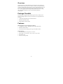
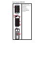
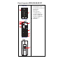
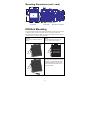
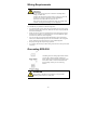
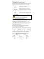
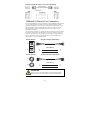
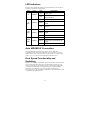
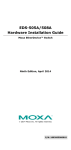
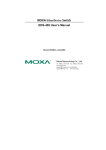
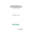
Moxa EtherDevice Switch
EDS-208 Series Hardware Installation Guide
Second Edition, June 2008
© 2008 Moxa Inc., all rights reserved.
Reproduction without permission is prohibited.
P/N: 1802002080000
Overview
The EDS-208 series of Moxa EtherDevice™ Switches are entry-level 8-port
Ethernet Switches that provide a cost-effective solution for industrial Ethernet
connections. EDS-208 provides a choice of 12 to 45 VDC power input or 18 to
30 VAC. The switches can operate reliably in a temperature range of -10 to
60°C, and the rugged hardware design makes EDS-208 perfect for ensuring
that your Ethernet equipment can be used in demanding industrial
environments.
Package Checklist
Moxa EDS-208 is shipped with the following items. If any of these items is
missing or damaged, please contact your customer service representative for
assistance.
y 1 EDS-208 or EDS-208-M-SC or EDS-208-M-ST
y Hardware Installation Guide
y Moxa Product Warranty booklet
Features
High Performance Network Switching Technology
y 10/100BaseT(X) (RJ45), 100BaseFX (SC/ST type, Multi mode)
y IEEE 802.3/802.3u/802.3x
y Store and Forward switching process type, 1024 address entries
Industrial Design
y Operating temperature ranges from -10 to 60°C
y Power inputs: 12 to 45 VDC or 18 to 30 VAC at 47 to 63 Hz
y IP30, plastic case
y DIN-Rail mounting ability
-2-
Panel Layout of EDS-208
Top View
1. Heat dissipation orifices
2. Terminal block for power input
and grounding
1
3. Moxa Logo
VV+
2
24 VDC/VAC
4. Power input LED
5. 10/100BaseT(X) Port
6. TP port’s 100 Mbps LED
7. TP port’s 10 Mbps LED
8. DIN-Rail kit
Front View
2
3
4
P
7
8
5
6
3
4
100
1
2
10
5
6
7
Rear View
8
-3-
Panel Layout of EDS-208-M-SC/ST
Top View
Heat dissipation orifices
2.
Terminal block for power input
3.
Moxa Logo
and grounding
1
VV+
2
24 VDC/VAC
4.
Power input LED
5.
10/100BaseT(X) Port
6.
TP port’s 100 Mbps LED
7.
TP port’s 10 Mbps LED
8.
FX port’s 100 Mbps LED
9.
100BaseFX Port
10. DIN-Rail kit
Front View
2
3
8
1.
4
P
100M
Rx
9
7
8
Tx
5
6
3
4
100
1
2
10
5
6
7
Rear View
10
-4-
Mounting Dimensions (unit = mm)
74
15
15
32
7
10.5
15.6
P
P
40.03
100M
Rx
23
7
7
8
5
6
8
Tx
V-
4
5
24 VDC/VAC
3
100
1
2
V+
6
74
3
100
76.2
100
12
4
100
1
10
2
10
40.03
86.5
EDS-208
Side View
EDS-208-M-SC/ST
Front View
Rear View Top View
DIN-Rail Mounting
The plastic DIN-Rail attachment plate should already be fixed to the rear panel
of EDS-208 when you take it out of the box. If you need to reattach the
DIN-Rail attachment plate to EDS-208, make sure the DIN-Rail kit is situated
towards the top, as shown in the figures below.
STEP 1:
Insert the top of the DIN-Rail into
the slot.
STEP 2:
The DIN-Rail attachment unit will
snap into place as shown below.
DIN-Rail
DIN-Rail
To remove Moxa EDS-208 from the
DIN-Rail, insert a flat-blade screw driver
horizontally into the DIN-Rail kit under
the EDS-208, and then pull it upwards
and release EDS-208 towards you away
from the DIN-Rail.
DIN-Rail
-5-
Wiring Requirements
ATTENTION
Safety First!
Be sure to disconnect the power cord before installing and/or
wiring your EDS-208.
Calculate the maximum possible current in each power wire and
common wire. Observe all electrical codes dictating the
maximum current allowable for each wire size.
If the current goes above the maximum ratings, the wiring could
overheat, causing serious damage to your equipment.
You should also pay attention to the following items:
y Use separate paths to route wiring for power and devices. If power wiring
and device wiring paths must cross, make sure the wires are perpendicular
at the intersection point.
y NOTE: Do not run signal or communications wiring and power wiring in
the same wire conduit. To avoid interference, wires with different signal
characteristics should be routed separately.
y You can use the type of signal transmitted through a wire to determine
which wires should be kept separate. The rule of thumb is that wiring that
shares similar electrical characteristics can be bundled together.
y Keep input wiring and output wiring separated.
y It is strongly advised that you label wiring to all devices in the system when
necessary.
Grounding EDS-208
Grounding and wire routing help limit the effects
of noise due to electromagnetic interference
(EMI). Run the ground connection from the right
most contact of the 3-contact terminal block to
the grounding surface prior to connecting
devices.
ATTENTION
This product is intended to be mounted to a well-grounded
mounting surface such as a metal panel.
-6-
Wiring the Power Inputs
The two left-most contacts of the 3-contact terminal block connector on
EDS-208’s top panel are used for both the DC and AC inputs of EDS-208. Top
and front views of one of the terminal block connectors are shown here.
STEP 1: Insert the negative/positive DC or AC
wires into the V-/V+ terminals.
STEP 2: To keep the DC or AC wires from
pulling loose, use a small flat-blade screwdriver
to tighten the wire-clamp screws on the front of
the terminal block connector.
STEP 3: Insert the plastic terminal block
connector prongs into the terminal block receptor,
which is located on EDS’s top panel.
ATTENTION
y Only connect to a class 2 power supply.
y Use 60/75°C copper (CU) wire 28-12 AWG only.
y Use a maximum torque of 4.5 in-lb.
Communication Connections
EDS-208 has 7 or 8 10/100BaseT(X) Ethernet ports, and 1 or 0 (zero)
100BaseFX (SC/ST-type connector) multi-mode fiber ports.
10/100BaseT(X) Ethernet Port Connection
The 10/100BaseT(X) ports located on EDS-208’s front panel are used to
connect to Ethernet-enabled devices.
Below we show pinouts for both MDI (NIC-type) ports and MDI-X
(HUB/Switch-type) ports, and also show cable wiring diagrams for
straight-through and cross-over Ethernet cables.
RJ45 (8-pin, MDI) Port Pinouts
RJ45 (8-pin, MDI-X) Port Pinouts
RJ45 (8-pin) to RJ45 (8-pin) Straight-Through Cable Wiring
-7-
RJ45 (8-pin) to RJ45 (8-pin) Cross-Over Cable Wiring
100BaseFX Ethernet Port Connection
The concept behind the SC/ST port and cable is quite straightforward. Suppose
you are connecting devices I and II. Contrary to electrical signals, optical
signals do not require a circuit in order to transmit data. Consequently, one of
the optical lines is used to transmit data from device I to device II, and the
other optical line is used to transmit data from device II to device I, for
full-duplex transmission.
All you need to remember is to connect the Tx (transmit) port of device I to the
Rx (receive) port of device II, and the Rx (receive) port of device I to the Tx
(transmit) port of device II. If you make your own cable, we suggest labeling
the two sides of the same line with the same letter (A-to-A and B-to-B, as
shown below, or A1-to-A2 and B1-to-B2).
SC-Port Pinouts
SC-Port to SC-Port Cable Wiring
A
A
B
B
Tx
Cable Wiring
Rx
A
B
ST-Port Pinouts
A
B
ST-Port to ST-Port Cable Wiring
A
A
B
B
Tx
Cable Wiring
Rx
A
B
A
B
ATTENTION
This is a Class 1 Laser/LED product. To avoid causing serious
damage to your eyes, do not stare directly into the Laser Beam.
-8-
LED Indicators
The front panel of EDS-208 contains several LED indicators. The function of
each LED is described in the table below.
LED
Color
State
On
P
10
(TP)
100
(TP)
100M
(FX)
AMBER
GREEN
GREEN
GREEN
Description
Power is being supplied to the
power input
Off
Power is not being supplied to
the power input
On
TP port’s 10 Mbps link is active
Blinking
Data is being transmitted at 10
Mbps
Off
TP Port’s 10 Mbps link is
inactive
On
TP port’s 100 Mbps link is active
Blinking
Data is being transmitted at 100
Mbps
Off
100BaseTX Port’s link is inactive
On
FX port’s 100 Mbps link is active
Blinking
Data is being transmitted at 100
Mbps
Off
100BaseFX Port’s link is inactive
Auto MDI/MDI-X Connection
The Auto MDI/MDI-X function allows users to connect EDS-208’s
10/100BaseTX ports to any kind of Ethernet device, regardless of how the
Ethernet cable is wired. This means that you can use either a straight-through
cable or cross-over cable to connect EDS-208 to Ethernet devices.
Dual Speed Functionality and
Switching
EDS208’s 10/100 Mbps switched RJ45 port auto negotiates with the connected
device for the fastest data transmission rate supported by both devices. All
models of EDS-208 are plug-and-play devices, so that software configuration
is not required at installation, or during maintenance. The half/full duplex
mode for the switched RJ45 ports is user dependent and changes (by
auto-negotiation) to full or half duplex, depending on which transmission speed
is supported by the attached device.
-9-
Switching, Filtering, and Forwarding
Each time a packet arrives at one of the switched ports, a decision is made
either to filter or to forward the packet. Packets with source and destination
addresses belonging to the same port segment will be filtered, constraining
those packets to one port, and relieving the rest of the network from the need to
process them. A packet with destination address on another port segment will
be forwarded to the appropriate port, and will not be sent to the other ports
where it is not needed. Packets that are used in maintaining the operation of the
network (such as the occasional multi-cast packet) are forwarded to all ports.
EDS-208 operates in the store-and-forward switching mode, which eliminates
bad packets and enables peak performance to be achieved when there is heavy
traffic on the network.
Switching and Address Learning
EDS-208 has an address table that can hold up to 1,000 node addresses, which
makes it suitable for use with large networks. The address tables are
self-learning, so that as nodes are added or removed, or moved from one
segment to another, EDS-208 automatically keeps up with new node locations.
An address-aging algorithm causes the least-used addresses to be deleted in
favor of newer, more frequently used addresses. To reset the address buffer,
power down the unit and then power it back up.
Auto-Negotiation and Speed Sensing
All of EDS-208’s RJ45 Ethernet ports independently support auto-negotiation
for speeds in the 10BaseT and 100BaseTX modes, with operation according to
the IEEE 802.3u standard. This means that some nodes could be operating at
10 Mbps, while at the same time, other nodes are operating at 100 Mbps.
Auto-negotiation takes place when a “live” RJ45 cable is connected to the
switch, and then each time a LINK is enabled. EDS-208 advertises its
capability for using either 10 Mbps or 100 Mbps transmission speeds, with the
device at the other end of the cable expected to similarly advertise. Depending
on what type of device is connected, this will result in agreement to operate at a
speed of either 10 Mbps or 100 Mbps.
If an EDS-208 RJ45 Ethernet port is connected to a non-negotiating device, it
will default to 10 Mbps speed and half-duplex mode, as required by the IEEE
802.3u standard.
Specifications
Technology
Standards
Processing Type
Address Table Size
Interface
RJ45 Ports
Fiber Ports
LED Indicators
IEEE802.3, 802.3u, 802.3x
Store and Forward, with IEEE802.3x full duplex,
non-blocking flow control
1,000 uni-cast addresses
10/100BaseT(X) auto negotiation speed, F/H
duplex mode, and auto MDI/MDI-X connection
100BaseFX ports (SC/ST connector)
Power, 10/100 M (TP port), 100 M (FX port)
- 10 -
Optical Fiber
Multi mode
Distance
5 km
Wavelength, nm
1300
Min. TX Output, dBm
-20
Max. TX Output, dBm
-14
Sensitivity, dBm
-34 to -30
Recommended Diameter
(Core/Cladding) μm
50/125 (1 dB/km, 800 MHz × km)
Power
Input Voltage
Input Current @ 24 VDC
Connection
Overload Current
Protection
Reverse Polarity Protection
Mechanical
Casing
Dimensions
Weight
Installation
Environment
Operating Temperature
Storage Temperature
Ambient Relative
Humidity
Regulatory Approvals
Safety
EMI
EMS
Shock
Free Fall
Vibration
WARRANTY
12 to 45 VDC, 18 to 30 VAC (47 to 63 Hz)
0.14 A (EDS-208)
0.23 A (EDS-208-M-SC/EDS-208-M-ST)
Removable 3-contact Terminal Block
1.1 A
Present
IP30 protection, plastic case
40 × 109 × 95 mm (W × H × D)
170 g
DIN-Rail
-10 to 60°C (14 to 140°F)
-40 to 70°C (-40 to 158°F)
5 to 95% (non-condensing)
UL 508 (pending)
FCC Part 15, CISPR (EN55022) class A
EN61000-4-2 (ESD),
EN61000-4-3 (RS),
EN61000-4-4 (EFT),
EN61000-4-5 (Surge),
EN61000-4-6 (CS)
IEC 60068-2-27
IEC 60068-2-32
IEC 60068-2-6
5 years
- 11 -
Technical Support Contact Information
www.moxa.com/support
Moxa Americas:
Toll-free: 1-888-669-2872
Tel:
+1-714-528-6777
Fax:
+1-714-528-6778
Moxa China (Shanghai office):
Toll-free: 800-820-5036
Tel:
+86-21-5258-9955
Fax:
+86-10-6872-3958
Moxa Europe:
Tel:
+49-89-3 70 03 99-0
Fax:
+49-89-3 70 03 99-99
Moxa Asia-Pacific:
Tel:
+886-2-8919-1230
Fax:
+886-2-8919-1231
- 12 -