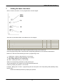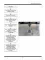
1
DACeco
operating manual
Dürkopp Adler AG, PO Box 17 03 51, D-33703 Bielefeld, Potsdamerstr. 190, D-33719 Bielefeld
Phone +49 (0) 521 9 25 00, Fax +49 (0) 521 9 25 24 35, www.duerkopp-adler.com
Ausgabe/ Edition : Mai 2012
Rev. Index : V 1.0.1
DACeco
© 2012 Dürkopp Adler AG
All rights reserved. No parts of this work may be reproduced in any form or by any means - graphic, electronic, or
mechanical, including photocopying, recording, taping, or information storage and retrieval systems - without the
written permission of the publisher.
Products that are referred to in this document may be either trademarks and/or registered trademarks of the
respective owners. The publisher and the author make no claim to these trademarks.
While every precaution has been taken in the preparation of this document, the publisher and the author assume no
responsibility for errors or omissions, or for damages resulting from the use of information contained in this
document or from the use of programs and source code that may accompany it. In no event shall the publisher and
the author be liable for any loss of profit or any other commercial damage caused or alleged to have been caused
directly or indirectly by this document.
Printed: Mai 2012 in Bielefeld, Germany
Doc Version: 1.0.1
Inhaltsverzeichnis
Table of contents
1
Important safety instructions
2
Scope of Delivery
6
2.1
3
Special accessories
6
3.1
3.2
3.3
4
4.1
4.2
5
4
User settings
7
Soft start
Stop position of the needle
Reducing the speed
7
8
8
9
Technical information
Technical specifications
Intended use
9
11
Assembly instructions
12
Fitting the reference value transm itter
Pow er supply (m ains connection)
Electrom agnetic com patibility (EMC)
Wiring diagram
Exam ple of fitting the DAC basic on a table top
Attaching the m otor
5.1
5.2
5.3
5.4
5.5
5.6
5.6.1
5.6.2
6
Using toothed or V-belts
Attaching the m otor under the table
12
13
15
16
18
19
19
19
Commissioning
20
7
Setting the basic functions
21
7.1
7.2
7.2.1
7.2.2
7.3
7.4
7.5
8
Num ber of stitches during soft start
Speed
Set soft start speed
Setting the m axim um speed
Holding force w hen idle
Setting the positions
Machine selection
22
22
22
22
24
24
26
Update of the controle
28
Update process
28
Error, warning and information messages
29
8.1
9
appendix
© 2012 Dürkopp Adler AG
3
DACeco
1
Important safety instructions
Important safety instructions
This DACeco sewing machine drive is manufactured and tested in accordance with the applicable conditions and
safety regulations and left the factory in a perfectly safe condition.
The user must observe all instructions and warning notices contained in these operating instructions in order to
maintain this condition and guarantee safe operation.
Any other use or use exceeding that specified, e.g. in the open air, in a wet or hazardous explosive environment,
is not regarded as intended use.. Use for the intended purpose includes observing the manufacturer's prescribed
conditions for operation, maintenance and repair.
The DACeco will only work safely and reliably if the control unit is used in accordance with these operating
instructions and its intended use.
Read these operating instructions carefully before unpacking and commissioning the DACeco. Familiarise
yourself with the safety, assembly, operating and maintenance instructions before using the DACeco, its
accessories and its additional attachments for the first time.
All operations on and with the DACeco must only be carried out in compliance with the following general and
particular safety instructions in the following sections of the operating instructions.
All persons affected by this must be made aware of these safety instructions and must comply with them. Noncompliance with the safety instructions may lead to personal injury, damage to equipment or malfunctions of and
damage to the drive itself.
The applicable accident prevention regulations in the respective user's country and the rules for safe and
professional working must be observed. The drive must only be assembled and commissioned by trained and
instructed persons.
Installation and commissioning of the DACeco must be carried out carefully by skilled workers so that the effects
of interference that may cause a risk to the health of personnel and dangerous conditions are reduced to a
minimum. Working on live parts and equipment is not permitted. Exceptions are governed by EN 50110.
Before removing covers, fitting additional attachments or accessories, e.g. reference value transmitters, photo
sensors etc., the control unit must be switched off, disconnected from the mains and you must wait until the
machine has come to a standstill [DIN VDE 0113 Part 301; EN 60204-3-1; IEC 204-3-1].
To reduce the risk of burns, fire, electric shock or injuries, alterations or modifications to the DACeco are strictly
forbidden.
No covers or protective devices may be removed during operation. Before leaving the work place, the machine's
on/off switch must be switched to the off position. If it is to be idle for long periods, the power plug must be
removed so that the drive cannot be switched on accidentally.
If additional attachments or equipment are connected to the DACeco control unit, these may only be operated at
low voltage that is produced by a safety transformer.
Do not put your hands near moving parts.
Do not operate the DACeco if aerosols (sprays) or oxygen are being used.
4
© 2012 Dürkopp Adler AG
Important safety instructions
These operating instructions are a component part of the DACeco and must be passed on to any subsequent
owners.
The instructions in the following sections are for your safety.
This symbol is a warning notice on the DACeco. It indicates life threatening voltages.
Caution - In the event of a malfunction, there may be life threatening voltages in this area
even after the electricity has been switched off (undischarged condensers).
The DACeco must only be operated with a protective earthing conductor in a working
protective earthing conductor system that complies with all local regulations and decrees.
The DACeco control unit is not an independently operating unit and is intended for installation in other machines.
Commissioning is not allowed until it has been ascertained that the machine in which the control unit is to be
installed complies with the provisions of the EU Directive.
© 2012 Dürkopp Adler AG
5
DACeco
2
Scope of Delivery
Scope of Delivery
1x control unit with power switch
1x reference value transmitter
1x foot pedal connecting rod
1x operating instructions
1x machine identification memory (Mach ID)
2.1
Special accessories
1x Synchronous motor with commutation or position transmitter
1x Under-table fitting unit with belt guard
1x External position transmitter or index signal
1x Memory dongle
6
© 2012 Dürkopp Adler AG
User settings
3
User settings
User settings of the DACeco can be set directly on the control unit. There are two buttons and a potentiometer
available for this.
3.1
Soft start
The soft start function can be turned on and off with S2. If the function is turned on, the corresponding LED is lit.
The last setting is saved when switching of the control unit and is available at the next start.
© 2012 Dürkopp Adler AG
7
DACeco
3.2
User settings
Stop position of the needle
Select the function Stop position of the needle with S1. If the stop position is set to "Needle up", the
corresponding LED is lit.
Pressing the button changes the stop position of the needle.
The last setting is saved when switching of the control unit and is available at the next start.
3.3
Reducing the speed
The speed can be adjusted to the current sewing process with the potentiometer. The basis is the maximum
speed listed for the machine class; reduce the speed starting at that point.
The set value remains until the operator adjusts the potentiometer.
The last setting is saved when switching of the control unit and is available at the next start.
8
© 2012 Dürkopp Adler AG
Technical information
4
Technical information
4.1
Technical specifications
Rated values:
Voltage
(UN ) [V]
230, mono-phase
Frequency
(fN ) [Hz]
50/60
Current (control unit)
Power (output)
[A]
(P2) [W]
1.6
375
Speed
(nn) [1/min]
4000
Torque
(Mn) [Nm ]
0.63
Motor moment of inertia
(Jmot ) [kgcm²]
0.5
(without strap disc)
Operating mode
Type of protection
Insulation class
S5 (40% ED at ts = 2.5 s)
Intermittent service with electrical braking,
relative power-on time 40%, run time 2.5 s
IP40
E
Limits:
Rated voltage range
[V]
Speed
(nmax ) [1/min]
Torque
(Mmax , short-term) [Nm]
5
Power
(P2max , short-term) [W]
1500
Moment of inertia
(Jmasch) [kg cm²]
4.5
190 - -240 + 20%/- 10%
mono-phase
6000
of the machine, reduced
to the motor shaft
Operating conditions:
Ambient temperature
Ambient temperature (average over 24h)
Humidity (relative)
© 2012 Dürkopp Adler AG
[°C]
[°C]
+ 5 - 45
< 35
85% at 30 °C
9
DACeco
Technical information
Control unit dimensions
10
© 2012 Dürkopp Adler AG
Technical information
4.2
Intended use
The DACeco is not a motor drive (control unit) that can be used on its own. The control unit is intended to be
fitted into other machines, i.e. sewing units and sewing equipment in the sewing thread processing industry and
trade.
Dry and clean areas must be provided to use the DACeco.
Use in wet, dusty or hazardous explosive environments is an infringement of the specified use.
Use for the intended purpose includes observing the manufacturer's prescribed conditions for operation,
maintenance and repair.
© 2012 Dürkopp Adler AG
11
DACeco
5
Assembly instructions
Assembly instructions
Before starting assembly, it is advisable to remove all parts from the packaging. The box contains the motor, the
control unit, the accessories and the operating instructions. Check the contents of the packaging to make sure
that everything is there. If you have any questions about assembly that the operating instructions do not answer,
please contact us or one of our service workshops. Assemble the motor in accordance with the individual
instructions and illustrations.
5.1
Fitting the reference value transmitter
The reference value transmitter is fastened under the machine table with an assembly bracket.
The reference value transmitter's pull and push rod are connected to the machine pedal by a connecting rod.
Screw the assembly bracket for the reference value transmitter under the machine table so that the reference
value transmitter's push and pull rod and the pedal connecting rod form as straight a line as possible in order
to ensure the best transfer of power between the reference value transmitter and the pedal.
The connecting rod and the pedal should form an angle as close to 90° as possible.
Make sure that the pedal moves freely.
12
© 2012 Dürkopp Adler AG
Assembly instructions
5.2
Power supply (mains connection)
Working on the electrical equipment (connection, maintenance, repairs) must only be done by or under the
supervision of a qualified electrician.
The DACeco control unit is intended to be connected to an earthed alternating current network with a rated
voltage in the range of 180V - 260 V 50/60 Hz.
Before connecting the mains lead, make sure that the rated voltage is within the rated voltage range
specified on the DACeco rating plate.
It must only be connected using a multi-pin plug with an earthing contact.
A fixed connection is not permitted. The following potentials must be connected:
Phase
(L1 or L2 or L3)
Neutral cable
(N)
Protective earth
(PE)
The DAC basic control unit is suitable for connection to the following mains:
TN mains with a directly earthed point, with a protective earth (PE) that is connected to this point.
TT mains with a directly earthed point where the protective earth (PE) is not connected to this mains earthing
point
.
IT mains that is not directly earthed.
L1
L1
L2
L2
L3
L3
N
PE
PE
DAC
DAC
DAC
DAC
© 2012 Dürkopp Adler AG
13
DAC
DACeco
Assembly instructions
TN -Netz
L1
L2
L3
N
PE
DAC
DAC
The following applies to TT mains and IT mains:
All units protected jointly by one protective device must be connected to the same earthing device by a
protective earth.
Simultaneously exposed units must be connected to a joint earth.
The following applies additionally to IT mains:
No active conductor of the unit must be earthed directly. The units must be connected individually, in groups or
in their entirety to a protective earth.
Mono-phase plug connection
14
© 2012 Dürkopp Adler AG
Assembly instructions
5.3
Electromagnetic compatibility (EMC)
The DACeco is prepared for installing in or attaching to sewing units and sewing equipment and meets the
relevant EMC regulations required for this (CDV IEC 204-3-1 44 sec 169) with a cable length of up to 500 mm on
each input or output socket. From experience, this is sufficient for sewing units. With sewing equipment, further
measures may be necessary because of longer cables, bad cabling, strong adjacent interference fields etc. The
effect of interference can be reduced or eliminated by doing the following:
- Via suitable filters, delay units, suitable cables and cable runs.
- Run cables of different electrical circuits (mains voltage, low voltage) physically separate from each other
in order to keep interference low.
- Reference potential wires for the electrical circuits or joint connection point: star-shaped wiring
with one or more reference points that are earthed with large cross-section insulated wires
.
- Electrically conductive parts of the sewing unit or sewing equipment must be connected to
the protective earth on the DACeco housing via voltage equalising cables. (Cables suitable for high
frequency:
extra-fine stranded wires with a cross section of at least 2.5 mm2 or wide copper bands.) When connecting
the potential equaliser, make sure of secure contact, i.e. on painted parts. the
connection must be made using toothed washers.
The following parts must be included in the potential equalisation:
-Sewing machine
-Sewing machine support frame
-Pedal
-Magnet or magnetic valve housings
-Holder for buttons
-Support frames for stackers, tape feed etc.
-Earth connections
Earth connections must be run from each part of the equipment to a common point. Braided, large crosssection wires must be used between moving parts and the housing and the earth connection must be kept as
short as possible.
-Signal transfer
Make sure that no interference voltage is transferred from the control and main current cables to signal cables
by using electrostatic and magnetic shielding, twisted wires and the cable run. (A cable crossover at right
angles is better than one with a smaller angle. Parallel runs must definitely be avoided.)
-Separating equipment parts
Equipment parts susceptible to interference (components with pulse processing and/or with low levels) should
be separated and/or shielded from switch equipment such as electromagnetic relays, thyristors etc.
-In spite of the fact that it is not susceptible to interference, the DACeco must not be operated in the immediate
vicinity of HF welding machines or similar equipment in order to avoid malfunctions. Should problems occur,
please contact the manufacturer.
© 2012 Dürkopp Adler AG
15
DACeco
5.4
Assembly instructions
Wiring diagram
sewing motor
interface
power switch
extern. synchronizer
messages LEDs
sewing motor
encoder interface
Led1
Led2
Rotary switch for
sewing speed
P1
foot pedal switch
interface
needle position
button with LED
S1
softstart button
with LED
machine
identification
interface
S2
16
© 2012 Dürkopp Adler AG
Assembly instructions
© 2012 Dürkopp Adler AG
17
DACeco
5.5
Assembly instructions
Example of fitting the DAC basic on a table top
eco
18
© 2012 Dürkopp Adler AG
Assembly instructions
5.6
Attaching the motor
There are three ways of attaching the motor to the sewing machine
1. Attaching directly to the top of the sewing machine
2. Attaching under the machine table
3. Installing in the top of the sewing machine
There are three different ways of transferring the drive torque from the motor to the machine
Options:
- Toothed belts and toothed belt discs
- V-belts and V-belt discs
- direct axial connection of the motor to the machine's main shaft
5.6.1
Using toothed or V-belts
When using toothed belts, the torque is transferred from the motor to the machine without slippage. The
transmission ratio between the motor and the machine is usually 1: 1. In this case, the machine requires no
reference position signal. Variable transmission ratios are possible depending on the ratio of the strap disk to the
hand wheel. However, in this case the machine requires a reference position signal.
When using V-belts, the torque is not transferred from the motor to the machine without slippage. The
transmission ratio between the motor and the machine is variable here. Here the machine requires a reference
position signal.
5.6.2
Attaching the motor under the table
The following parts are needed:
Bracket to hold the motor
V-belt disc for the motor shaft
V-belt disc for the machine shaft
V-belt
Belt guard
Synchroniser if necessary
© 2012 Dürkopp Adler AG
19
DACeco
6
Commissioning
Commissioning
Before commissioning the control unit, the following must be ensured, checked or set:
The correct assembly of the drive, position sensor and any accessories used
If necessary, the correct setting of the motor rotation direction
The correct maximum speed that is compatible with the sewing machine
The position settings
The settings of the remaining relevant parameters
Saving the set values
20
© 2012 Dürkopp Adler AG
Setting the basic functions
7
Setting the basic functions
With S1 and S2, the DACeco can be programmed to a lesser degree.
LED1
LED2
P1
S1
S2
There are six parameters listed in the table that can be changed.
1
2
3
4
5
6
Parameter
Soft start stitches
Soft start speed
Maximum speed
Holding force
Needle positions and reference position
Machine selection (DA dongle with parameter sets required)
Min
1
200
200
0
-
Max
20
1000
6000
6
-
Unit
Stitches
rpm
rpm
A
-
To access the programming mode, keep S1 pressed when turning on the control unit.
Once the programming mode is active and the corresponding parameter can be selected, LED2 flashes.
Buttons S1 and S2 have the following functions in programming mode:
Confirmation - Keep S1 (OK) pressed (> one second)
Cancellation - Keep S2 ( ESC) pressed (> one second)
Plus - Briefly press S1 (+) (< one second)
Minus - Briefly press S2 (-) (< one second)
Select the corresponding parameter by briefly pressing S1.
The LED allocated to S1 indicates the currently selected parameter.
Confirm by keeping S1 pressed > one second.
Example: Briefly press S1 twice = programming the soft start speed. The corresponding LED repeatedly briefly
flashes twice.
Confirm the selected parameter by keeping S1 pressed.
© 2012 Dürkopp Adler AG
21
DACeco
7.1
Setting the basic functions
Number of stitches during soft start
If the programming level of a parameter is selected, buttons S1 and S2 have the following functions:
Confirmation - Keep S1 (OK) pressed (> one second)
Cancellation - Keep S2 ( ESC) pressed (> one second)
Plus - Briefly press S1 (+) (< one second)
Minus - Briefly press S2 (-) (< one second)
Briefly pressing S1 increases the number of soft start stitches by one stitch; briefly pressing S2 reduces the
number by one stitch.
The set value is then indicated by the flashing LEDs.
S1 LED : 10s digit
S2 LED : 1s digit
The LEDs flash every 0.5 seconds. After a pause of 1.5 seconds, the sequence is repeated until it is confirmed
or cancelled.
Confirm the programmed result by pressing S1. Leave the programming level by pressing S2.
7.2
Speed
7.2.1
Set soft start speed
If the programming level of a parameter is selected, buttons S1 and S2 have the following functions:
Confirmation - Keep S1 (OK) pressed (> one second)
Cancellation - Keep S2 ( ESC) pressed (> one second)
Plus - Briefly press S1 (+) (< one second)
Minus - Briefly press S2 (-) (< one second)
Briefly pressing S1 increases the soft start speed by 100rpm; briefly pressing S2 reduces it by 100rpm.
The set value is then indicated by the flashing LEDs.
S1 LED : 100s digit
The LEDs flash every 0.5 seconds. After a pause of 1.5 seconds, the sequence is repeated until it is confirmed
or cancelled.
Confirm the programmed result by pressing S1. Leave the programming level by pressing S2.
7.2.2
Setting the maximum speed
If the programming level of a parameter is selected, buttons S1 and S2 have the following functions:
Confirmation - Keep S1 (OK) pressed (> one second)
Cancellation - Keep S2 ( ESC) pressed (> one second)
Plus - Briefly press S1 (+) (< one second)
Minus - Briefly press S2 (-) (< one second)
Briefly pressing S1 increases the maximum speed by 100rpm; briefly pressing S2 reduces it by 100rpm.
The set value is then indicated by the flashing LEDs.
22
© 2012 Dürkopp Adler AG
Setting the basic functions
S1 LED : 1000s digit
S2 LED : 100s digit
The LEDs flash every 0.5 seconds. After a pause of 1.5 seconds, the sequence is repeated until it is confirmed
or cancelled.
Confirm the programmed result by pressing S1. Leave the programming level by pressing S2.
© 2012 Dürkopp Adler AG
23
DACeco
7.3
Setting the basic functions
Holding force when idle
If the programming level of a parameter is selected, buttons S1 and S2 have the following functions:
Confirmation - Keep S1 (OK) pressed (> one second)
Cancellation - Keep S2 ( ESC) pressed (> one second)
Plus - Briefly press S1 (+) (< one second)
Minus - Briefly press S2 (-) (< one second)
Briefly pressing S1 increases the holding force by 0.5 A; briefly pressing S2 reduces it by 0.5 A.
The set value is then indicated by the flashing LEDs.
S1 LED : Pre-decimal position
S2 LED : Decimal place
The LEDs flash every 0.5 seconds. After a pause of 1.5 seconds, the sequence is repeated until it is confirmed
or cancelled.
Confirm the programmed result by pressing S1. Leave the programming level by pressing S2.
This function prevents unwanted "wandering" of the needle when the machine has come to a standstill.
The effect can be checked by turning the hand wheel.
Holding force takes effect when idle
- for a stop in the seam
- after the end of the seam
The effect can be adjusted
The higher the set value, the stronger the holding force
7.4
Setting the positions
The angle settings required on the machine, e.g. "Needle down" or "Thread lever up" are saved in the control
unit. A reference position is required to establish a relationship between the position sensor information and the
actual mechanical position. The reference position may be different depending on the parameter settings,
normally "Point at which the needle penetrates the stitch plate (EP)"
The reference position must be set:
on first commissioning
after replacing the control unit
after replacing the motor or the incremental sensor.
24
© 2012 Dürkopp Adler AG
Setting the basic functions
© 2012 Dürkopp Adler AG
25
DACeco
7.5
Setting the basic functions
Machine selection
If the programming level of a parameter is selected, buttons S1 and S2 have the following functions:
Cancellation - Keep S2 ( ESC) pressed (> one second)
Plus - Briefly press S1 (+) (< one second)
Minus - Briefly press S2 (-) (< one second)
Select the next parameter set by briefly pressing S1. Select the previous parameter set by briefly pressing S2.
The set value is then indicated by the flashing LEDs.
LED1 : 10s digit
LED1 : 1s digit
The LEDs flash every 0.5 seconds. After a pause of 1.5 seconds, the sequence is repeated until it is confirmed or
cancelled.
Confirm the programmed result by pressing S1. Leave the programming level by pressing S2.
In order to load a new parameter set, insert a DA dongle with parameter sets in the pedal interface.
You can find this software on the homepage of Dürkopp Adler.
You can find a list with the machine classes in the additional txt-file.
Example:
The following machine classes could select:
1. 171-131610
2. 173-141610
3. 271-140342-01
4. 272-140342-01
5. 281-140342-01
6. 838-x70522-M
7. 867-190x22-M
8. 867-190x42-M
9. 867-290x22-M
10. 867-290x42-M
11. 869-180x22-M
12. 887-1601x2-M
13. 888-x601x2-M
14. 888-x60522-M
15. 888-3561x2-M
You can change the selection with the upper and lower buttons.
The actual selected class will be shown by flashing of the LEDs.
Example select class 281 – 140342-01:
Push 5 times the upper button.
The lower LED will flash 5 times and after this it has got a longer break. The cycle will be repeated
Example select class 887-1601x2-M:
Push 12 times the upper button.
Die obere LED blinkt einmal für die Zehn und die untere LED blinkt zweimal für die 2.
The upper LED will flash one time for the ten and the lower LED will flash 2 times for the 2 after this both LEDs have got
a longer break. The cycle will be repeated
26
© 2012 Dürkopp Adler AG
Setting the basic functions
To accept the selection push and hold the upper button for approx. 2 sec.
Now the parameters will be loaded and you can see it by flashing of the Message LED and you can hear a signal.
If the Message LED is flashing in a constant cycle and you can’t hear any signal you can switch off the control.
Now connect the pedal with the control.
© 2012 Dürkopp Adler AG
27
DACeco
8
Update of the controle
Update of the controle
You can update the controle software and the default parameter of the machine.
You need a memory dongle (9835 901005) with the controle software to update the controle.
You can find the software on the homepage of Dürkopp Adler.
8.1
Update process
Connect all plugs of the machine head with the control. It is very important that the machine ID is connected with the
control.
Der Speicher-Dongle mit der Steuerungssoftware muss an die Pedal-Schnittstelle angeschlossen werden.
Insert a DA-Dongle with the control software at the connector of the foot pedal.
Machine-ID
Switch on the control. Both LEDs will be flashing
That’s means that the software will be updated. If the the update was successfully you can hear a signal and the lowest
LED will be flashing. The LEDs (Power und Message) are activated.
28
© 2012 Dürkopp Adler AG
Error, warning and information messages
9
Error, warning and information messages
The DACeco control unit contains three groups of messages that are divided as follows:
Degree
Description
Error
Serious error
Turn off the control unit and correct the error.
Warning
Eliminate the condition that caused the warning and the control unit will continue to work normally.
Information Press OK
You can continue to work; only emergency running properties may be available.
The messages are visualised via LED2. The coding is displayed via LED2
flashing every 0.5 seconds. The flashing sequence is then interrupted for two seconds and
repeated.
Degree
Code
Error or information description
Remedial measures
Warning
1
Travel stop
- Check the tilt sensor on the machine
Information 2
Low voltage warning (1st threshold) - Check mains voltage
(mains voltage < 180V AC)
- Stabilise mains voltage
- Use generator
Warning
3
Pedal position is not in position 0
- When switching on the control unit, take foot off
pedal
Error
4
Pedal not connected
- Connect analogue pedal
Error
5
Sewing motor encoder plug (Sub-D, - Insert the encoder lead into the control unit. Use the
9-pin) not connected.
correct interface.
Error
6
Motor stalls
- Eliminate sluggish movement in the sewing machine
Error
7
Sewing motor overload
- Eliminate sluggish movement in the sewing machine
Error
8
Sewing motor error
Sewing motor plug (AMP) is not
connected.
- Check the connection and if necessary plug in.
- Test sewing motor phases (R= 2.8 Ohm, highresistance compared with PE)
- Replace sewing motor
- Replace control unit
Error
9
Sewing motor insulation error
- Check motor phase and PE for low-resistance
connection
- Replace sewing motor
Error
10
High voltage error, mains voltage
>290V for some time
- Check mains voltage, if rated voltage exceeded
permanently - stabilise or use generator
Error
11
EEprom communication error
- Check the connection of the Mach ID
- Turn off the control unit, wait until LEDs are off,
restart
Information 12
No valid data on external EEprom
- Check the connection of the Mach ID
- Turn off the control unit, wait until LEDs are off,
restart
- Update software
Error
13
Low voltage failure (2nd threshold)
(mains voltage < 150V AC)
- Check mains voltage
- Stabilise mains voltage
- Use generator
Error
14
Sewing motor turning in the wrong
direction
- Replace encoder
- Check that the motor plug is in the correct place and
change if necessary
© 2012 Dürkopp Adler AG
29
DACeco
Degree
Error, warning and information messages
Code
Error or information description
Remedial measures
- Check wiring in the machine distributor and change if
necessary
- Test motor phases and check for value
Error
15
Excess sewing motor current,
internal current increase >25A
- Replace control unit
Error
16
Maximum speed exceeded
- Replace encoder
Error
17
AC RDY time-out , intermediate
- Check mains voltage
circuit voltage has not reached the - If mains voltage OK, replace control unit
defined threshold in the given time.
Information 18
No valid data on internal and
external EEprom
- Check the connection of the Mach ID
- Turn off the control unit, wait until LEDs are off,
restart
- Update software
Information 19
No valid data on internal EEprom
- Check the connection of the Mach ID
- Turn off the control unit, wait until LEDs are off,
restart
- Update software
30
© 2012 Dürkopp Adler AG