1
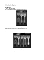
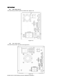
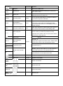
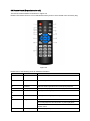
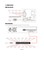
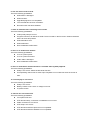
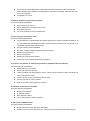
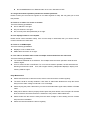
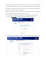
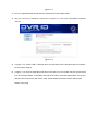
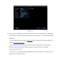
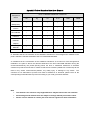
EN and ENCSeries Hardware User Manual ENC 2bays NVR ENC16 4bay NVR 16 Channel 2U case NVR Table of Contents 1 2 3 System Capability ...................................................................................................................................7 1.1 EN and ENC Capabilities (NVR units) ......................................................................................7 1.2 EH-RTHD Capabilities (Hybrid units) ........................................................................................7 Features and Specifications ...............................................................................................................8 2.1 Overview ........................................................................................................................................8 2.2 Features.........................................................................................................................................8 2.3 Specifications ................................................................................................................................9 Front Panel and Rear Panel ............................................................................................................. 11 3.1 Front Panel .................................................................................................................................. 11 3.1.1 3.1.2 3.1.3 3.2 Rear Panel ..................................................................................................................................15 3.2.1 3.2.2 3.2.3 3.3 5 ENC 2bay Series .................................................................................................................15 ENC 4bay Series ....................................................................................................................15 EN Series..............................................................................................................................17 Bidirectional talk .........................................................................................................................18 3.3.1 3.3.2 4 ENC 2bay series.................................................................................................................. 11 ENC 4bay Series .................................................................................................................... 11 EN Series..............................................................................................................................13 Device-end to PC-end ........................................................................................................18 PC-end to the device-end ..................................................................................................19 3.4 Mouse Operation ........................................................................................................................19 3.5 Remote Control (Dependent on the unit )...............................................................................20 HDD Installation..................................................................................................................................22 4.1 ENC Series..................................................................................................................................22 4.2 EN Series ....................................................................................................................................22 Network Connection ..........................................................................................................................24 ENC Series Connection ........................................................................................................................24 EN Series Connection ...........................................................................................................................24 6 FAQ ......................................................................................................................................................25 7 Appendix A HDD Capacity Calculation ...........................................................................................30 8 Appendix B Compatible SATA HDD................................................................................................31 9 Appendix C Compatible USB List ....................................................................................................33 10 Appendix D Compatible Displayer List........................................................................................35 11 Appendix E No-IP DDNS ..............................................................................................................36 Appendix H Toxic or Hazardous Materials or Elements.......................................................................41 Welcome Thank you for purchasing our network video recorder! This quick start guide is designed to be a reference tool for your system. Please open the accessory bag to check the items one by one in accordance with the list below. Contact your local retailer if something is missing or damaged in the bag. Important Safeguards and Warnings 1.Electrical safety All installation and operation here should conform to your local electrical safety codes. We assume no liability or responsibility for all the fires or electrical shock caused by improper handling or installation. 2.Transportation security Heavy stress, violent vibration or water splash are not allowed during transportation, storage and installation. 3.Installation Keep upwards. Handle with care. Do not apply power to the NVR before completing installation. Do not place objects on the NVR 4.Qualified engineers needed All the examination and repair work should be done by the qualified service engineers. We are not liable for any problems caused by unauthorized modifications or attempted repair. 5.Environment The NVR should be installed in a cool, dry place away from direct sunlight, inflammable, explosive substances and etc. This series product shall be transported, storage and used in the environment ranging from 0℃ to 55 ℃ 6. Accessories Be sure to use all the accessories recommended by manufacturer. Before installation, please open the package and check all the components are included. Contact your local retailer ASAP if something is broken in your package. 7. Lithium battery Improper battery use may result in fire, explosion, or personal injury! When replace the battery, please make sure you are using the same model! Before your operation please read the following instructions carefully. Installation environment Keep away from extreme hot places and sources; Avoid direct sunlight; Keep away from extreme humid places; Avoid violent vibration; Do not put other devices on the top of the NVR; Be installed in well ventilated place; do not block the vent. Accessories Check the following accessories after opening the box: Please refer to the packing list in the box * Component Name ENC Series EN Series NVR ■ ■ 7-pin SATA cable ■ ■ Power cable ■ ■ Network cable ■ ■ Remote control ■ ■ Black optical mouse ■ ■ Power adapter ■ □ Quick start guide ■ ■ Product warranty ■ ■ card Product certificate ■ ■ CD ■ ■ Plastic pad ■ ■ card 1 System Capability 1.1 EN and ENC Capabilities (NVR units) The maximum system capability that this product series supports is the following 4-IP 1080P with transmission rate 6mbps every channel @ 30 fps 8-IP 1080P with transmission rate 2mbps every channel @ 12 fps 16-IP 1080P with transmission rate 1.5mbps every channel @ 5 fps Model System setting max capability for 1080P Resolution 4-IP series 4-channel @ 1080P @ 30fps @ 6144 kbps 8-IP series 8-channel @ 1080P @ 12fps @ 2048 kbps 16-IP series 16-channel @ 1080P @ 5fps @ 1536 kbps 1.2 EH-RTHD Capabilities (Hybrid units) The maximum system capability that this product series supports is the following 4 - CH D1 with transmission rate 1Mbps every channel @ 12fps 4 - IP 1080P with transmission rate 6Mbps every channel @ 12fps 8 - CH D1 with transmission rate 768kbps every channel @ 6fps 8 – IP 1080P with transmission rate 2Mbps every channel @ 6fps 16 - CH 1080P with transmission rate 384kbps every channel @ 3fps 16 - IP 1080P with transmission rate 1.5Mbps every channel @ 3fps Model 4-ch series 8-ch series 16-ch series System setting max capability for 1080P Resolution 4 - channel @ D1 @ 12fps @ 1024 kbps 4-IP @ 1080P @ 12fps @ 6144 kbps 8-channel @ D1 @ 6fps @ 768 kbps 8-IP @ 1080P @ 6fps @ 2048 kbps 16-channel @ 1080P @ 5fps @ 384 kbps 16-channel @ 1080P @ 5fps @ 1536 kbps 2 Features and Specifications 2.1 Overview It is a high performance network video recorder. This series product support local preview, multiple-window display, recorded file local storage, remote control and mouse shortcut menu operation, and remote management and control function. All these functions support this series product to be used in various situations. This series product supports centre storage, front-end storage and client-end storage. The monitor zone in the front-end can be set in anywhere. Working with other front-end devices such as IPC, NVS, this series product can establish a strong surveillance network via the CMS. In the network system, there is only one network cable from the monitor centre to the monitor zone in the whole network. There is no audio/video cable from the monitor centre to the monitor zone. The whole project is featuring of simple connection, low-cost, low maintenance work. This series NVR can be widely used in many areas such as public security, water conservancy, transportation and education. 2.2 Features User Management Storage ·Each group has different management powers that can be edited freely. Every user belongs to an exclusive group. Via corresponding setup (such as alarm setup and schedule setup), you can backup related audio/video data in the network video recorder. Support Web record and record local video and storage the file in the client end. Respond to external alarm simultaneously (within 200MS), based on user’s pre-defined relay setup, system can process the alarm input correctly and prompt user by screen and voice (support pre-recorded audio). Alarm Support central alarm server setup, so that alarm information can remotely notify user automatically. Alarm input can be derived from various connected peripheral devices. Alert you via EMAIL. Through network, sending audio/video data compressed by IPC or NVS to client-ends, then the data will be decompressed and display. If bandwidth is big enough, latency is less than 500ms Network Monitor Support max 10 connections Transmit audio/video data by HTTP, TCP, UDP, MULTICAST, RTP/RTCP and etc. Window Split in one monitor. Support 1/4/9/16-window display. Record Transmit some alarm data or alarm info by SMTP. Support WEB access in WAN. Adopt the video compression and digital process to show several windows Support schedule record function. Save the recorded files in the HDD, client-end PC, or network storage server. You can search or playback the saved files at the local-end or via the Web. Support network backup, USB record backup function, the recorded files can be saved in network storage server, peripheral USB device, burner and etc. Supervise NVR configuration and control power via Ethernet. Support management via WEB. Support peripheral equipment management such as protocol setup and port connection. Support transparent data transmission through RS232/RS485. Support switch between NTSC and PAL. Support real-time system resources information and running statistics display. Support log file. Local GUI output. Shortcut menu operation via mouse. IR control function. Shortcut menu operation via remote control. Support IPC or NVS remote video preview and control. Backup Network Management Peripheral Equipment Management Auxiliary 2.3 Specifications Parameter Operation Specification ENCSeries EN Series Embedded Linux real-time operation system System Operation WEB/Local GUI Interface Video H.264/MPEG4 Compression Encode For H.264, it max supports 16*D1, 8*720,4*1080P. Capacity Audio G.711a Compression Video Output 1-channel VGA analog video output. Video Input 4/8/16-ch network compression digital video input HDMI 1-ch HDMI output. Audio Input Audio Output Window Split Multiple-channe N/A 1-ch bidirectional audio input 1-channel bidirectional talk output. N/A 4/9/16-window Max 16-channel playback. l Playback Alarm Input Alarm Output 4/8/16-ch alarm input. 3-ch alarm output 6-ch alarm output Relay output. Relay (DC 30V 1A,AC 125V 0.5A(Activation output)) Including one controllable DC +12V output. Storage RS232 Port 2 built-in SATA port s 8 built-in SATA ports N/A 1 peripheral eSATA port One RS232 port to debug transparent COM data. One RS485 port to control PTZ. Support various protocols. RS485 port USB Port 2 peripheral USB ports. 4 peripheral USB port. Network One RJ45 10/100M/1000M self-adaptive Ethernet port. Connection One power port, power adapter. Input Power Port Power Button Power Button IR Remote One power port, AC100~240V 50+2% Hz. DC 12V. One power button in the rear panel. One power button in the front panel. N/A One IR remote control receiver in the front panel. Control Receiver Clock Indication Light Built-in clock. 16 record status indication lights 16 record status indication lights One power status indication light. One system running status indication light. One alarm status indication light. One remote control indication light. One network status indication light. One HDD status indication light. Power <12W(Exclude HDD) <40W(Exclude HDD) Consumption Working 0℃~+50℃ Temperature Working 10℅-90℅ Humidity Air pressure Dimension Weight Installation 86kpa-106kpa 440mm*300mm*42.6mm 1.5~2.5 KG(Exclude HDD) Desk installation/Rack installation 440mm*460mm*89mm 5.5~6.5KG(Exclude HDD) 3 Front Panel and Rear Panel 3.1 Front Panel 3.1.1 ENC 2bay series The -1U series NVR front panel is shown as below. See Figure 3-1. Figure 3-1 Please refer to the following sheet for detail information Figure 3-3. 3.1.2 ENC 4bay Series The -1U series NVR front panel is shown as below. See Figure 3-1. Figure 3-2 Please refer to the following sheet for detail information Figure 3-3. Name Icon Function Power button, press this button for three seconds to boot up or shut Power button down NVR. One-window monitor mode, click this button to display assistant function: PTZ control and image color. Backspace function: in numeral control or text control, press it for 1.5seconds to delete the previous character before the cursor. Assistant Fn In motion detection setup, working with Fn and direction keys to realize setup. In text mode, click it to switch between numeral, English character(small/capitalized) and etc. In HDD management interface, you can click it to switch HDD record information and other information (Menu prompt) System Power System power up status IR Receiver It is to receive the signal from the remote control. HDD abnormity indicator The red light is for the HDD abnormity Alarm Status when alarm is triggered color will change to blue Network abnormity indicator The red light is for the network abnormity USB port To connect USB storage device, USB mouse. Drive Bays HDD bays with locks Figure 3-3 3.1.3 EN Series The EN series front panel is shown as in Figure 3-4. Figure 3-4 Please refer to the following sheet for detail information. Name Icon Function Power button, press this button for three seconds to boot up or shut Power button Number button Input number more than 10 down NVR. Input Arabic number 0-9 Switch channel If you want to input a number more than 10, please click this button -/-- and then input. In Shift textbox, click this button to switch between numeral, English(Small/Capitalized),donation and etc. Enable or disable tour. Activate current control, modify setup, and then move up and down. Up/ Down 、 Increase/decrease numeral. Assistant function such as PTZ menu. Left/ Right Shift current activated control, and then move left and right. When playback, click these buttons to control playback bar. Go to previous menu, or cancel current operation. ESC ESC When playback, click it to restore real-time monitor mode. Confirm current operation Enter ENTER Go to default button Go to menu Record REC Manually stop/start recording, working with direction keys or numeral keys to select the recording channel. One-window monitor mode, click this button to display assistant function: PTZ control and image color. Assistant Fn Backspace function: in numeral control or text control, press it for 1.5seconds to delete the previous character before the cursor. In motion detection setup, working with Fn and direction keys to realize setup. In text mode, click it to switch between numeral, English character(small/capitalized) and etc. In HDD management interface, you can click it to switch HDD record information and other information (Menu prompt) Realize other special functions. Fast play Slow play Various fast speeds and normal playback. Multiple slow play speeds or normal playback. Play previous In playback mode, playback the previous video Play Next In playback mode, playback the next video In menu setup, go to down ward of the dropdown list. In normal playback or pause mode, click this button to reverse Reverse/Pause playback In reverse playback, click this button to pause playback. Play/Pause Window switch Mult In normal playback click this button to pause playback In pause mode, click this button to resume playback. Click it to switch one-window/multiple-window. In real-time monitor mode it works as left/right direction key. Shuttle(outer ring) Playback mode, counter clockwise to forward and clock wise to backward. Up/down direction key. Playback mode, turn the inner dial to realized frame by frame Jog(inner dial) playback. (Only applies to some special versions.) USB port To connect USB storage device, USB mouse. Remote control ACT Remote control indication light Status If there is Fn indication light, current status indication light is null. PWR Power indication light Record light 1-16 For 4/8/16 IR Receiver IR It is to receive the signal from the remote control. indication light Status indication light Power indication light ch series ,it becomes on when system is recording. 3.2 Rear Panel 3.2.1 ENC 2bay Series The ENC 2bay seriesreal panel is shown as in Figure 3-5. Figure 3-5 3.2.2 ENC 4bay Series The ENC 4bay series is shown as in Figure 3-6. Figure 3-6 Please refer to the following sheet for detailed information. Port Name Connection Function USB port. Connect to USB mouse. Network port 10M/100M self-adaptive Ethernet port. Connect to the network cable. eSATA eSATA port The external SATA port. It can be connected to the peripheral devices of SATA port. RS232 232 debug COM. HDMI High Definition Multimedia Interface HDMI VGA VGA video output port VGA RS232 It is for general COM debug to configure IP address or transfer transparent COM data. High definition video signal output port. Transmit the clear video and multiple-track data (Uncompressed)to the device of HDMI(High definition media interface) VGA video output port. Output analog video signal. It can connect to the monitor to view analog video. They are to receive the signal from the external alarm 1~3 Alarm input port. source. When your alarm input device is using 1~3 external power, please make sure the device and the NVR have the same ground. Ground Ground end NO~C Port NO~C alarm output port. Relay out I/O port Output alarm signal to the alarm device. Please make sure there is power to the external alarm device. Tx Programming Port Programming Port Rx RS485_A port. It is the cable A. You can connect to the control devices such as speed dome PTZ. A+ RS485 communication port RS485_B.It is the cable B. You can connect to the control devices such as speed dome PTZ. BPower port 48 volts POE power supply Power port 12 volts System Power supply Power button Power on/off button. Bi-directional talk Bi-directional talk POE port 4 Port POE switch Basic Network port Network port 3.2.3 EN Series The 2U series rear panel is shown as below. See Figure 3-7. Figure 3-7 Please refer to the following sheet for detailed information. Port Name Connection Function Power button Power on/off button. Power input port Input AC 120-220 MIC OUT Audio output port RCA Audio output port. Output analog audio signal to the devices such as sound box. MIC IN Audio input port RCA Bidirectional talk input port. Receive the analog signal from the devices such as speaker or pickup. 1~16 Alarm input port. 1~16 I/O port Four groups of alarm input ports. The first group is from port 1 to port 4, the second group is from port 5 to port 8, the third group is from 9 to 12, and the fourth group is from 13 to 16. They are to receive the signal from the external alarm source. There are two types; NO (normal open)/NC (normal close). When your alarm input device is using external power, please make sure the device and the NVR have the same ground. NO1~NO5 Ground end Alarm input ground end. Alarm output port 1~5 5 groups of alarm output ports. (Group 1:port NO1~C1,Group 2:port NO2~C2,Group 3:port NO3~C3.group 4: port NO4~C4、Group 5: port NO5、C5、NC5).Output alarm signal to the alarm device. Please make sure there is power to the external alarm device. C1~C5 NC5 NO:Normal open alarm output port. C:Alarm output public end. NC: Normal close alarm output port. A B RS485 port RS485_A port. It is the cable A. You can connect to the control devices such as speed dome PTZ. RS485_B.It is the cable B. You can connect to the Port Name Connection Function control devices such as speed dome PTZ. CTRL 12V Controllable 12V power output. It is to control the on-off relay output. You can use it to enable device alarm function. It can also be used as the power input for some alarm devices such as the smoke detector. +12V eSATA +12V power output port. It is to provide the power to the peripheral devices such as camera or alarm device. The connected device current shall be less than 1A. Network port 10M/100M self-adaptive Ethernet port. Connect to the network cable. eSATA port The external SATA port. It can be connected to the peripheral devices of SATA port. Please pay attention to the HDD jumper when you connect the external HDD. USB port. Connect to USB mouse. RS232 232 debug COM. It is for general COM debug to configure IP address or transfer transparent COM data. HDMI High definition multimedia interface High definition video signal output port. VGA VGA video output port Transmit the clear video and multiple-track data (Uncompressed)to the device of HDMI(High definition media interface) VGA VGA video output port. Output analog video signal. It can connect to the monitor to view analog video. 3.3 Bidirectional talk 3.3.1 Device-end to PC-end Device Connection Please connect the speaker or the pickup to the first audio input port in the device rear panel. Then connect the earphone or the sound box to the audio output port in the PC. Login the Web and then enable the corresponding channel real-time monitor. Please refer to the following interface to enable bidirectional talk. Figure 3-8 Listening Operation At the device end, speak via the speaker or the pickup, and then you can get the audio from the earphone or sound box at the pc-end. 3.3.2 PC-end to the device-end Device Connection Connect the speaker or the pickup to the audio output port in the PC and then connect the earphone or the sound box to the first audio input port in the device rear panel. Login the Web and then enable the corresponding channel real-time monitor. Please refer to the above interface (Figure 3-8) to enable bidirectional talk. Listening Operation At the PC-end, speak via the speaker or the pickup, and then you can get the audio from the earphone or sound box at the device-end. 3.4 Mouse Operation Please refer to the following sheet for mouse operation instruction. Left click mouse When you have selected one menu item, left click mouse to view menu content. Modify checkbox or motion detection status. Click combo box to pop up dropdown list In input box, you can select input methods. Left click the corresponding button on the panel you can input numeral/English character (small/capitalized). Here ← stands for backspace button. _ stands for space button. When input special sign, you can click corresponding numeral in the front panel to input. For example, click numeral 1 you can input“/” , or you can click the numeral in the on-screen keyboard directly. Double left click mouse Implement special control operation such as double click one item in the file list to playback the video. In multiple-window mode, double left click one channel to view in full-window. Double left click current video again to go back to previous multiple-window mode. Right click In real-time monitor mode, pops up shortcut menu. mouse Exit current menu without saving the modification. Press In numeral input box: middle Switch the items in the check box. button Page up or page down Move Select current control or move control Increase or decrease numeral value. mouse Drag mouse Select motion detection zone Select privacy mask zone. 3.5 Remote Control (Dependent on the unit ) The remote control interface is shown as in Figure 3.9. Please note remote control is not our standard accessory and it is not included in the accessory bag. Figure 3-9 Please refer to the following sheet for detailed information. Serial Number Name Function 1 Power button Click it to boot up or shut down the device. 2 Address Click it to input device number, so that you can control it. 3 Forward Various forward speeds and normal speed playback. 4 Slow play Multiple slow play speeds or normal playback. Next record In playback mode, playback the next video. Previous record In playback mode, playback the previous video. Play/Pause In pause mode, click this button to realize normal playback. 5 6 7 In normal playback click this button to pause playback. In real-time monitor mode, click this button to enter video search menu. Reverse/pause Reverse playback pause mode, click this button to realize 8 normal playback. In reverse playback click this button to pause playback. Cancel 9 10 Go back to previous menu or cancel current operation (close upper interface or control) Record Start or stop record manually In record interface, working with the direction buttons to select the record channel. Click this button for at least 1.5 seconds, system can go to the Manual Record interface. 11 Direction keys Switch current activated control, go to left or right. In playback mode, it is to control the playback process bar. Aux function(such as switch the PTZ menu) 12 Confirm /menu key go to default button go to the menu 13 Multiple-window Switch between multiple-window and one-window. switch 14 Auxiliary key In 1-ch monitor mode: pop up assistant function :PTZ control and Video color. Switch the PTZ control menu in PTZ control interface. In motion detection interface, working with direction keys to complete setup. 15 0-9 number key Input password, channel or switch channel. Shift is the button to switch the input method. Figure 3-1 4 HDD Installation For the first time install, please be aware that whether the HDDs have been installed. Strongly recommended to use the HDDs which we suggest you to use (high speed HDD that above 7200 rounds), we do not suggest you to use PC specified HDD. 4.1 ENC Series Pleas follow the steps listed below to install the HDD. ① Remove the drive bay ②Fix the four screws on the ③Place the Drive bay back 4.2 EN Series ① Unscrew the screws on the rear panel and cover the upper cover. ② Place the HDDs on the HDD bracket and fix the HDD on the bracket with four screws. ③ Use data cable to connect main board and HDD port, then connect the power (the other end) cable to the HDD port. ④ After wires are connected, place the upper cover on the device and twist the screws on the rear panel. Important Before you replace the HDD, please make sure you have shut down the device and unplug the power cable! 5 Network Connection ENC Series Connection EN Series Connection Cameras connected to the External POE switch has to be set with a computer. Figure 5-1 6 FAQ 1. Device can not boot up properly. There are following possibilities: Input power is not correct. Power connection is not correct. Power switch button is damaged. Program upgrade is wrong. HDD malfunction or something wrong with HDD ribbon. Seagate DB35.1,DB35.2,SV35 or Maxtor 17-g has compatibility problem. Please upgrade to the latest version to solve this problem. Front panel error. Main board is damaged. 2. Device often automatically shuts down or stops running. There are following possibilities: Input voltage is not stable or it is too low. HDD malfunction or something wrong wit the ribbon. Button power is not enough. Front video signal is not stable. Working environment is too harsh, too much dust. Hardware malfunction. 3. System can not detect hard disk. There are following possibilities: HDD is broken. HDD ribbon is damaged. HDD cable connection is loose. Main board SATA port is broken. 4. There is no video output whether it is one-channel, multiple-channel or all-channel output. There are following possibilities: Program is not compatible. Please upgrade to the latest version. Brightness is 0. Please restore factory default setup. There is no video input signal or it is too weak. Check privacy mask setup or your screen saver. Device hardware malfunctions. 5. Real-time video color is distorted. There are following possibilities: When using BNC output, NTSC and PAL setup is not correct. The real-time video becomes black and white. Device and monitor resistance is not compatible. Video transmission is too long or degrading is too huge. Device color or brightness setup is not correct. 6. Can not search local records. There are following possibilities: HDD ribbon is damaged. HDD is broken. Upgraded program is not compatible. The recorded file has been overwritten. Record function has been disabled. 7. Video is distorted when searching local records. There are following possibilities: Video quality setup is too low. Program read error, bit data is too small. There is mosaic in the full screen. Please restart the device to solve this problem. HDD data ribbon error. HDD malfunction. Device hardware malfunctions. 8. There is no audio when monitor. There are following possibilities: It is not a power picker. It is not a power acoustics. Audio cable is damaged. Device hardware malfunctions. 9. There is audio when monitor but there is no audio when system playback. There are following possibilities: Setup is not correct. Please enable audio function Corresponding channel has no video input. Playback is not continuous when the screen is blue. 10. Time display is not correct. There are following possibilities: Setup is not correct Battery contact is not correct or voltage is too low. Crystal is broken. 11. Device can not control PTZ. There are following possibilities: Front panel PTZ error PTZ decoder setup, connection or installation is not correct. Cable connection is not correct. PTZ setup is not correct. PTZ decoder and device protocol is not compatible. PTZ decoder and device address is not compatible. When there are several decoders, please add 120 Ohm between the PTZ decoder A/B cables furthest end to delete the reverberation or impedance matching. Otherwise the PTZ control is not stable. The distance is too far. 12. Motion detection function does not work. There are following possibilities: Period setup is not correct. Motion detection zone setup is not correct. Sensitivity is too low. For some versions, there is hardware limit. 13. Can not log in client-end or web. There are following possibilities: For Windows 98 or Windows ME user, please update your system to Windows 2000 sp4. Or you can install client-end software of lower version. Please note right now, our device is not compatible with Windows VISTA control. ActiveX control has been disabled. No dx8.1 or higher. Please upgrade display card driver. Network connection error. Network setup error. Password or user name is invalid. Client-end is not compatible with device program. 14. There is only mosaic no video when preview or playback video file remotely. There are following possibilities: Network fluency is not good. Client-end resources are limit. There is multiple-cast group setup in device. This mode can result in mosaic. Usually we do not recommend this mode. There is privacy mask or channel protection setup. Current user has no right to monitor. Device local video output quality is not good. 15. Network connection is not stable. There are following possibilities: Network is not stable. IP address conflict. MAC address conflict. PC or device network card is not good. 16. Burn error /USB back error. There are following possibilities: Burner and device are in the same data cable. System uses too much CPU resources. Please stop record first and then begin backup. Data amount exceeds backup device capacity. It may result in burner error. Backup device is not compatible. Backup device is damaged. 17. Keyboard can not control device. There are following possibilities: Device serial port setup is not correct Address is not correct When there are several switchers, power supply is not enough. Transmission distance is too far. 18. Alarm signal can not been disarmed. There are following possibilities: Alarm setup is not correct. Alarm output has been open manually. Input device error or connection is not correct. Some program versions may have this problem. Please upgrade your system. 19. Alarm function is null. There are following possibilities: Alarm setup is not correct. Alarm cable connection is not correct. Alarm input signal is not correct. There are two loops connect to one alarm device. 20. Remote control does not work. There are following possibilities: Remote control address is not correct. Distance is too far or control angle is too small. Remote control battery power is low. Remote control is damaged or device front panel is damaged. 21. Record storage period is not enough. There are following possibilities: Camera quality is too low. Lens is dirty. Camera is installed against the light. Camera aperture setup is not correct. HDD capacity is not enough. HDD is damaged. 22. Can not playback the downloaded file. There are following possibilities: There is no media player. No DXB8.1 or higher graphic acceleration software. There is no DivX503Bundle.exe control when you play the file transformed to AVI via media player. No DivX503Bundle.exe or ffdshow-2004 1012 .exe in Windows XP OS. 23. I forgot local menu operation password or network password Please contact your local service engineer or our sales engineer for help. We can guide you to solve this problem. 24. There is no video. The screen is in black. There are following possibilities: IPC IP address is not right. IPC port number is not right. IPC account (user name/password) is not right. 25. The displayed video is not complete. Please cheek current resolution setup. If the current setup is 1920*1080, then you need to set the monitor resolution as 1920*1080. 26. There is no HDMI output. There are following possibilities: Displayer is not in HDMI mode. HDMI cable connection is not right. 27. The video is not fluent when I view in multiple-channel mode from the client-end. There are following possibilities: The network bandwidth is not sufficient. The multiple-channel monitor operation needs at least 100M or higher. Your PC resources are not sufficient. For 16-ch remote monitor operation, the PC shall have the following environment: Quad Core, 2G or higher memory, independent displayer, display card memory 256M or higher. Daily Maintenance Please use the brush to clean the board, socket connector and the chassis regularly. The device shall be soundly earthed in case there is audio/video disturbance. Keep the device away from the static voltage or induced 143H143Hvoltage. Please unplug the power cable when you remove the audio/video signal cable, RS232 or RS485 cable. Always shut down the device properly. Please press the power button in the front pane for at least three seconds to shut down the device. Otherwise it may result in HDD malfunction. Please make sure the device is away from the direct sunlight or other heating sources. Please keep the sound ventilation. Please check and maintain the device regularly. 7 Appendix A HDD Capacity Calculation Calculate total capacity needed by each device according to video recording (video recording type and video file storage time). Step 1: According to Formula (1) to calculate storage capacity q i that is the capacity of each channel needed for each hour, unit Mbyte. qi d i 8 3600 1024 (1) In the formula: d i means the bit rate, unit Kbit/s Step 2: After video time requirement is confirmed, according to Formula (2) to calculate the storage capacity mi , which is storage of each channel needed unit Mbyte. m i = q i × hi × D i (2) In the formula: hi means the recording time for each day (hour) Di means number of days for which the video shall be kept Step 3: According to Formula (3) to calculate total capacity (accumulation) qT that is needed for all channels in the device during scheduled video recording. c qT mi (3) i 1 In the formula: c means total number of channels in one device Step 4: According to Formula (4) to calculate total capacity (accumulation) qT that is needed for all channels in device during alarm video recording (including motion detection). c qT mi ×a% i 1 In the formula:a% means alarm occurrence rate (4) 8 Appendix B Compatible SATA HDD Manufacturer Series Model Capacity Port Mode Seagate Barracuda.10 ST3750640AS 750G SATA Seagate Barracuda.10 ST3500630AS 500G SATA Seagate Barracuda.10 ST3400620AS 400G SATA Seagate Barracuda.10 ST3320620AS 320G SATA Seagate Barracuda.10 ST3250620AS 250G SATA Seagate Barracuda.10 ST3250820AS 250G SATA Seagate Barracuda.10 ST3160815AS 160G SATA Seagate Barracuda.10 ST380815AS 80G SATA Seagate Barracuda.9 ST3160811AS 160G SATA Seagate Barracuda.9 ST3120811AS 120G SATA Seagate Barracuda.9 ST380811AS 80G SATA Seagate Barracuda.9 ST380211AS 80G SATA Seagate Barracuda.11 ST3750330AS 750G SATA Seagate Barracuda.11 ST3500320AS 500G SATA Maxtor DiamondMax 20 STM3320820AS 320G SATA Maxtor DiamondMax 20 STM3250820AS 250G SATA Maxtor DiamondMax 21 STM3160211AS 160G SATA Maxtor DiamondMax 21 STM380211AS 80G SATA Maxtor DiamondMax 21 STM340211AS 40G SATA Westem Digital Cariar SE WD3200JD 320G SATA Westem Digital Cariar SE WD3000JD 300G SATA Westem Digital Cariar SE WD2500JS 250G SATA Westem Digital Cariar SE WD2000JD 200G SATA Westem Digital Cariar SE WD1600JD 160G SATA Westem Digital Cariar SE WD1600JS 160G SATA Westem Digital Cariar SE WD1200JS 120G SATA Westem Digital Cariar SE WD800JD 80G SATA Westem Digital Cariar WD1600AABS 160G SATA Westem Digital Cariar WD800BD 80G SATA Westem Digital Cariar SE16 WD7500KS 750G SATA Westem Digital Cariar SE16 WD5000KS 500G SATA Westem Digital Cariar SE16 WD4000KD 400G SATA Westem Digital Cariar SE16 WD3200KS 320G SATA Westem Digital Cariar SE16 WD2500KS 250G SATA 9 Appendix C Compatible USB List Manufacturer Model Capacity Sandisk Cruzer Micro 512M Sandisk Cruzer Micro 1G Sandisk Cruzer Micro 2G Sandisk Cruzer Freedom 256M Sandisk Cruzer Freedom 512M Sandisk Cruzer Fredom 1G Sandisk Cruzer Freedom 2G Kingston Data Traveler II 1G Kingston Data Traveler II 2G Kingston Data Traveler 1G Kingston Data Traveler 2G Maxell USB Flash Stick 128M Maxell USB Flash Stick 256M Maxell USB Flash Stick 512M Maxell USB Flash Stick 1G Maxell USB Flash Stick 2G Kingax Super Stick 128M Kingax Super Stick 256M Kingax Super Stick 512M Kingax Super Stick 1G Kingax Super Stick 2G Netac U210 128M Netac U210 256M Netac U210 512M Netac U210 1G Netac U210 2G Teclast Ti Cool 128M Teclast Ti Cool 256M Teclast Ti Cool 512M Teclast Ti Cool 1G Teclast Ti Cool 2G 10 Appendix D Compatible Displayer List Brand Model Dimension (Unit: inch) BENQ(LCD) ET-0007-TA 19-inch (wide screen) DELL(LCD) E178FPc 17-inch BENQ(LCD) Q7T4 17-inch BENQ(LCD) Q7T3 17-inch LENOVO(LCD) LXB-L17C 17-inch SANGSUNG(LCD) 225BW 22-inch (wide screen) LENOVO(CRT) LXB-FD17069HB 17-inch LENOVO(CRT) LXB-HF769A 17-inch LENOVO(CRT) LX-GJ556D 17-inch Samsung (LCD) 2494HS 24-inch Samsung (LCD) P2350 23-inch Samsung (LCD) P2250 22-inch Samsung (LCD) P2370G 23-inch Samsung (LCD) 2043 20-inch Samsung (LCD) 2243EW 22-inch LG(LCD) W1942SP 19-inch LG(LCD) W2243S 22-inch LG(LCD) W2343T 23-inch BENQ(LCD) G900HD 18.5-inch BENQ(LCD) G2220HD 22-inch PHILIPS(LCD) 230E 23-inch PHILIPS(LCD) 220CW9 23-inch PHILIPS(LCD) 220BW9 24-inch PHILIPS(LCD) 220EW9 25-inch 11 Appendix E No-IP DDNS Please double click DDNS to go to the configuration interface. You can see an interface is shown as in Figure 11-1. Figure 11-1 DDNS Type: You can select from the dropdown list. DVRID.com, No-IP and DynDNS. Server IP: Server IP of the DDNS type Port: default port is 80 for dvrid.com. Domain Name: Domain name created with DDNS service provider. User: User name from your DDNS service provider. Password: User name from the DDNS service provider. Highlight the icon in front of Enable to enable the DDNS server configuration. It’s a system of dynamic DNS service. If you do not have a Static IP address on the Internet, you need to have a dynamic IP. It is to say your IP address changes after a certain period of time. You can follow the steps listed below to display image on your device even your IP is dynamic. You need to use a DDNS service and create a domain name that is not necessarily direct use the IP address. After completed configuration in the device DDNS service can constantly inform the latest device’s connection IP, and modify its IP on the table of data from the server. Then we have a constant domain name in the Web browser, along with the HTTP port, send a request to identify the car IP of the domain name typed. The server will direct the domain name to the IP connection, thus allowing access to the device which does not have a fixed IP in the network. Note: It is important to note that to gain access to the device in a local network, it is necessary to achieve the redirect the port of your modem or router to your device. To receive domain name in the DVRID.com DDNS service, please follow the steps listed below. 1. Please visit www.dvrid.com; the page for DVRID appears as below. See Figure 11-2. Figure 11-2 2. Left click mouse on the “Register” button, account Information interface is shown as in Figure 11-3. Figure 11-3 3. Fill in the requested fields and answer the Captcha then click Submit button. 4. Now you can see an interface is shown as in Figure 11-4. You have successfully created an account. Figure 11-4 5. In Figure 11-4, Create a URL or domain name. the first field is for the domain and the next field is for the system serial no. 6. In Figure 11-5, input corresponding host name in the filed. You can use this name to access device from an external network. In the field to the right of the name, select the desired area. This is your domain name for access to the device. Click “Create additional domain names” button at the bottom of the page. Figure 11-5 7. Please go to the device and access the MAIN MENU> SETTING> NETWORK> DDNS. Input server IP you get in the above step. Select the DDNS Type as DVRID and highlight the icon in front of Enable to enable the DDNS function. Now fill the fields as described below, and click OK to save current setup. • Server IP: DVRID.com • Port: Enter the port 80. • Domain Name: Enter the domain name created in step 4. • User: Enter your username (email address) created in step 2. • Password: Enter the password created in step 2. The figure Configuration file of No-IP is shown as in Figure 11-6. Figure 11-6 8. Now you have completed device setup. Open Internet Explorer ® in another foreign network with Internet access, unlike the network where the device is connected to, you need to follow the steps listed below: 1. Enter the address into your browser: http://URLor domain name the field created in step 8. For example: http://manuel.dvrid.com 2. If the device HTTP port is 80, just type the domain name. Otherwise, enter in the browser address as: http://nome the field created in Step 8: port number of HTTP. For example: http://myhome.dvrid.com:82 3. Press Enter. The system will ask install application webrec.cab control or not. Please click Yes to perform a successful connection. Appendix H Toxic or Hazardous Materials or Elements Toxic or Hazardous Materials or Elements Component Name Pb Hg Cd Cr VI PBB PBDE ○ ○ ○ ○ ○ ○ ○ ○ ○ ○ ○ ○ Circuit Board ○ ○ ○ ○ ○ ○ Fastener ○ ○ ○ ○ ○ ○ ○ ○ ○ ○ ○ ○ ○ ○ ○ ○ ○ ○ ○ ○ ○ ○ ○ ○ Sheet Metal(Case) Plastic Parts (Panel) Wire and Cable/Ac Adapter Packing Material Accessories Note O: Indicates that the concentration of the hazardous substance in all homogeneous materials in the parts is below the relevant threshold of the SJ/T11363-2006 standard. X: Indicates that the concentration of the hazardous substance of at least one of all homogeneous materials in the parts is above the relevant threshold of the SJ/T11363-2006 standard. During the environmental-friendly use period (EFUP) period, the toxic or hazardous substance or elements contained in products will not leak or mutate so that the use of these (substances or elements) will not result in any severe environmental pollution, any bodily injury or damage to any assets. The consumer is not authorized to process such kind of substances or elements, please return to the corresponding local authorities to process according to your local government statutes Note This manual is for reference only. Slight difference may be found in the user interface. All the designs and software here are subject to change without prior written notice. Please visit our website or contact your local service engineer for more information.