1
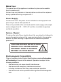
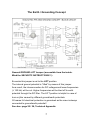
PHONO PRE-AMPLIFIER
PPA V600
USER´s MANUAL
1
Content
Theme
Page
About Violectric
Safety Instructions
The Earth / Grounding Concept
Connection / Connectors
General
Operation
Input Impedances
Input Capacities
Setting the Equalizer
Opening the Case / Dismantling
Things to know
Disposal
Technical Data
Jumper Setting
Conformity Statement
Warranty
2
3
5
7
9
10
11
15
16
17
20
21
24
25
26
27
28
Cordial thanks for your decision in favour of a
product !
is a trademark and product line of Lake People
electronic GmbH. Lake People electronic GmbH develops,
manufactures and distributes products in the professional range, for
broadcast, television, airports, exhibition halls, festival venues, theatres,
large-scale installations, private studios and more. In the private sector
as well, Lake People products become increasingly popular due to their
outstanding quality.
The
trademark and product line is specially intended to
supply the Hi-Fi and High-End market with its specific requirements.
Who develops
equipment ?
devices are exclusively developed in Germany by the
engineers of Lake People electronic GmbH. In doing so, the team of
developers can draw on twenty years of experience and countless
products for the pro-audio domain.
Among others, the first German-made 20-bit A/D and D/A converters
were developed by Lake People in the early nineties of the past century.
Who manufactures
equipment ?
devices are exclusively manufactured in Germany by
Lake People electronic GmbH or contractors in the company's vicinity.
- put high emphasis
Lake People - and by association
on domestic manufacturing. As well, all component suppliers are chosen
in order achieve the main part of added value inland.
3
How do
devices get to the customer ?
devices can be obtained from respective specialist
suppliers. If there is none such accessible regionally, the customer is
supported by transregional distribution partners (google may help...)
and, of course, by Lake People electronic GmbH themselves.
… and if it doesn't work like it should ?
devices are covered by a 24-month warranty. In case of
any malfunction during this period, they can be shipped to the
manufacturer directly. Of course, the client will benefit from
's and Lake People's full technical support even when
warranty has expired. Any technical questions or need for advice is
welcome.
is a subsidiary of
LAKE PEOPLE electronic GmbH
Turmstrasse 7a
D-78467 Konstanz
Fon +49 (0) 7531 73678
Fax +49 (0) 7531 74998
www.violectric.de
www.lake-people.de
www.violectric.com
www.lake-people.com
4
General Safety Instructions
WARNING
For your protection, please read the following:
Water, Liquids, Moisture:
This appliance should not be used near water or other sources of liquids.
Care should be taken so that objects do not fall and liquids are not spilled into
the enclosure through openings.
Power Sources:
The appliance should be connected to a power supply only of the type described
in the operating instructions or as marked on the appliance.
Grounding:
Care should be taken that this appliance is operated with proper grounding only.
Power Cord:
Power supply cords should be routed so that they are not likely to be walked on
or pinched by items placed upon or against them, paying particular attention to
cords at plugs, convenience receptacles, and the point where they exit from the
appliance.
This unit is equipped with a 3-pole mains cable with German 3-pin mains plug.
In some countries this unit must be operated with a mains adaptor, supplied by
the owner.
Please refer to the table below to connect a mains plug:
OVERVIEW: POWER CORD FUNCTION AND COLORS
CONDUCTOR
L
N
E
LIVE
COLOR
Alternativ
BROWN
BLACK
NEUTRAL
BLUE
WHITE
PROTECTIVE EARTH
GREEN+YELLOW
GREEN
U.K. Mains Plug Warning:
A moulded mains plug that has been cut off from the cord is unsafe. Discard the mains
plug at a suitable disposal facility.
NEVER UNDER ANY CIRCUMSTANCES SHOULD YOU INSERT A DAMAGED OR
CUT MAINS PLUG INTO A 13 AMP POWER SOCKET. Do not use the mains plug
without the fuse cover in place. Replacement fuse covers can be obtained from your local
retailer. Replacement fuses are 13 amps and MUST be ASTA approved to BS 1362.
5
Mains Fuse:
The mains fuse of this appliance is soldered in place and accessible
from the inside only!!
A blown fuse may indicate an internal problem and should be replaced
during qualified servicing or repair work !!
Power Supply:
Connect this unit to the power source indicated on the equipment rear
panel only to ensure safe operation !!
This unit is provided with a multi-mode switch-mode supply and accepts
mains voltages from 90 … 250 V AC and thus is suitable for glueless
worldwide operation.
Service / Repair:
To reduce the risk of fire or electric shock, the user should not attempt to
service the appliance beyond the measures described in the operating
manual. All other servicing or repair should be referred to qualified
personnel !!
VOR DEM ÖFFNEN NETZSTECKER
ZIEHEN!! PULL MAINS BEFORE
OPENING!! AVANT D´OUVRIER
RETIREZ LA FICHE MALE!!
Electromagnetic Compatibility
This unit conforms to the Product Specifications noted as Declaration
of Conformity at the end of this manual. Operation is subject to the
following conditions:
- this device may not cause harmful interferences
- this device must accept any interference received,
including interference that may cause undesired operation
- this device must not be operated within significant electromagnetic
field
6
The Earth / Grounding Concept
General GROUND-LIFT Jumper (accessible from the inside.
Mind the SECURITY INSTRUCTIONS !! ):
Ex-works this jumper is set to the LIFT position.
The internal ground potential is “lifted” by means of this jumper.
As a result, the interconnection for DC voltages and lower frequencies
(< 150 Hz) will be cut. Higher frequencies will be bled off to earth
potential through the RC filter. The LIFT position is helpful in case of
hum or jitter caused by different ground/earth potentials.
Of coarse full electrical protection is garanteed as the case is always
connected to ground/earth potential!
See also: page 20 / 26, Technical Appendix.
7
Unfortunately there is no general recommendation how to solve hum
and jitter problems - or even minimize them. The best way to succeed is
to check different options !! In case of balanced cables, it should always
been verified if the shield of the cable is connected to the shell of the
XLR connector. The shell is ALWAYS connected to earth potential when
the connector is inserted !!
Concerning ANALOG inputs and outputs, the relationship between
ground and earth may be modified. Electrical safety is always ensured,
since the earth conductor is permanently connected to the enclosure !!
XLR GROUD-LIFT Jumper (accessible from the inside.
Mind the SECURITY INSTRUCTIONS !! ):
G(ROUND): Ex-works all jumpers are set to "G" (ground) position.
Pin 1 is connected to the internal ground reference.
High frequency interference is deflected to the case via a
100 nF capacitor.
L(IFT):
The interconnection between Pin 1 and ground is open.
High frequency interference is deflected to the case via a
100 nF capacitor. This jumper position is specifically
useful if the unit is equipped with transformers !!
C(ASE):
Pin 1 is connected to the case, the 100 nF capacitor is
bridged. This jumper position may be varied together with
the General GROUND-LIFT jumper.
See also: page 20 / 26, Technical Appendix.
Please note that with jumpers not in the ex-works position
EMC emission might occur,
for which the user is responsible only !
8
Connection / Connectors for analog signals
9
GENERAL INFORMATION
The PPA V600 is a high-quality, two-channel preamplifier for movingcoil and moving-magnet pickup systems.
Its groundbreaking design allows a variety of setting possibilities second
to none. Due to the implementation of professional instrumentation
amplifiers in the input section, it offers extraordinarily low noise figures
and extreme bandwidth even at high gain.
Features:
- balanced inputs via gold-plated Neutrik 5-pin XLR sockets
- unbalanced inputs via gold-plated cinch sockets
- input impedance internally switchable, 9 settings
- input capacitance internally switchable, 16 settings
- low-noise instrumentation amplifier of extreme bandwidth
- front-switchable gain, in six steps from +36 to +60 dB
- front-face balance control +/- 2 dB
- internally selectable equalization: RIAA / NAB / BBC / FLAT
- internally switchable 20Hz high-pass according to IEC specifications
- individual-channel layout
- DC-coupled signal path
- top-grade operational amplifiers within the signal path
- high-quality MKP capacitors within the signal path
- 0.1 and 1% metal film resistors exclusively
- <0.05 dB aberration from RIAA curve due to eight reference points
- unbalanced outputs via gold-plated cinch sockets
- balanced outputs via gold-plated Neutrik XLR connectors
- lowest-noise and lowest-ripple switched-mode supply
combined with and precision linear-regulated powering
- internally switchable ground lift
- rugged aluminium case with Nextel coating
- solid aluminium laser-engraved front panel
10
THE CASE
The PPA V600's case as well as the front/rear panels are made of solid
aluminium. This choice of material ensures high mechanical stability and
resistance.
EARTH AND GROUND
The PPA V600's case is grounded. Internal reference ground is bridged
to protective earth by means of a jumper. The jumper is set to the 'LIFT'
position (see also: page 7 "Earth/Ground concept" and pages 20/26
"Technical Appendix").
POWER SUPPLY
Mains power is provided via a three-pin IEC/CEE socket and mating
"cold-appliance" mains cord with Schuko-type plug. Because of the
employed multi-mode switch-mode supply the actual AC voltage may
vary between 90 and 250 volts AC for flawless operation.
The US and Japan version comes with a US style mains cord.
Bith switch-mode supplies will output 24 V DC. External filters will cut
any high frequency glitches. Line regulators form the internal operating
voltages of +/-18 V.
MAINS FUSE
The 0.25A time-lag fuse is soldered in place on the circuit board. In
case, it must be replaced with a fuse of the same type only.
CAUTION !!
MIND THE SAFETY INSTRUCTIONS:
A blown fuse indicates an internal fault and
should be replaced during qualified repair or
servicing only !!
11
THE BALANCED SIGNAL INPUT
For the connection of balanced signals a gold-plated 5-pin XLR socket
is located in the 'cartridge input' section on the rear of the unit, denoted
as 'BAL'.
5-pin XLR Pin-Out:
PIN 1
Left (+) PHASE
PIN 2
Left (-) PHASE
PIN 3
Ground
PIN 4
Right (-) PHASE
PIN 5
Right (+) PHASE
THE UNBALANCED INPUTS
Or the connection of unbalanced signals two gold-plated cinch sockets
are located in the 'cartridge input' section, denoted as 'UNBAL L' and
'UNBAL R'.
INPUT SELECTION
The cinch inputs sockets are activated ex-works.
In order to utilize the balanced inputs, the unit must be opened and the
two related jumpers set from 'U' (unbalanced) to 'B' (balanced).
See also: technical appendix page 20 / 26.
12
OPERATION
The following controls and displays are located on the front panel:
POWER SWITCH
The unit is turned on by means of the power switch. The blue LED
beneath the switch indicates that the unit is ready for operation.
GAIN SWITCH
The gain switch on the front panel allows easy signal gain control,
offering six possible settings: 30 / 36 / 42 / 48 / 54 and 60 dB. Gain is
set for both channels individually by means of a precision resistor array,
thus offering highly accurate stereo matching at lowest crosstalk.
Settings of 30...42 dB are usually suited for MM systems, while 48...60
dB are intended for the use with MC pickups. So-called 'high output MC'
systems are best operated at 42...48 dB gain.
As noise level rises proportional to gain, it is always recommended to
choose the lowest practical gain setting !
BALANCE CONTROL
By technical means, pickup systems usually don't present exact channel
balance, and even sophisticated systems can exhibit a channel
matching error of 1...2 dB. This can lead to a shifted stereo image
13
which, however, can easily be compensated by the balance control, with
an adjustment range of +/-2 dB and a detented centre position.
In order to maintain minimum crosstalk, balance is set by means of fine
adjustment of the right channel, instead of a conventional balance pot
as found on other devices.
AMPLIFIERS / INTERNAL SETTINGS
The low input signals are fed to a so-called instrumentation amplifier,
originally intended for the use with professional microphones. This
allows extremely low-noise amplification vastly superior to any other
design, while offering an internal bandwidth of >200 kHz even at 60 dB
gain.
Susceptibility to hum as induced by low-frequency equalization and
interference to the cable between turntable and input can be
significantly reduced by balanced coupling between the pickup system
and the amplifier, using balanced cabling.
In order to precisely match with any pickup model, 9 input impedance
and 16 input capacitance settings can be selected by DIP switches
inside the unit.
While the RIAA equalization curve is the most commonly used, the PPA
V600 can also be switched to NAB, BBC or FLAT curve. In addition, it
provides a 20Hz IEC high-pass filter, which can be inserted in the signal
path by DIP switches. All the filters are passive designs, using highquality and non-ageing MKP capacitors. By means of eight reference
points, the RIAA curve is precisely maintained with an accuracy of 0,05
dB.
Channel circuits are completely separate, in order to obtain optimum
crosstalk rejection.
14
INPUT IMPEDANCE
Input impedance can be precisely matched to the respective MC
(moving-coil) system by means of switchable input impedance. The
value matching best can either be read in the pickup's technical
specifications, or optimized by further recommendations and listening
tests.
Settings comprise 10, 90, 100, 130, 150, 250, 330, 1k and 47k ohms,
whereas 47k is recommended for MM (moving magnet) systems. The
unit's case must be opened to change this setting.
See also: technical appendix, pages 20 / 26.
The DIP-switches marked with “MC” may be set as follows:
Note: Setting ex works is 47kOhm
15
INPUT CAPACITANCE
Input capacitance can be precisely matched to the respective MM
(moving magnet) system by means of switchable input capacitance. The
value matching best can either be read in the pickup's technical
specifications, or optimized by further recommendations and listening
tests.
Settings comprise 33, 66, 110, 150, 180, 210, 260, 300, 330, 370, 410,
450, 480, 520, 560 and 600 pF.
Input impedance for MM systems should be set to 47k ohms !
The unit's case must be opened to change this setting.
See also: technical appendix, pages 20 / 26.
The DIP-switches marked with “MM” may be set as follows:
Note: Setting ex works is 33 pF
16
EQUALIZATION CURVES
17
EQUALIZATION CURVES
Due to technical considerations, the signal stored on vinyl records has
been equalized during manufacture, i.e. low frequencies are reduced
and high frequencies are boosted. Upon playback in turn, an equalizer
as accurate as possible is employed in order to re-linearize frequency
response. There were several dozens of equalization curves in record
history, but fortunately the so-called RIAA curve (Recording Industry
Association of America) has established itself as the most common
standard. Nevertheless, one may encounter records manufactured
using NAB (National Association of Broadcasters), BBC (British Broadcasting Corporation) or FLAT (no treble EQ) equalization curves, which
the V600 can easily cope with by means of its switching capabilities.
Furthermore, a 20 Hz highpass or 'rumble' filter according to IEC
(International Electrotechnical Commission) can be switched into circuit.
See also: technical appendix, pages 20 / 26.
Note: Setting ex works is RIAA
18
THE UNBALANCED OUTPUTS
The unbalanced output signal is available at gold-plated cinch sockets
on the rear panel. They are denoted as 'UNBAL L' for the left channel,
and 'UNBAL R' for the right one respectively.
Output impedance is significantly less than 1 ohm !
THE BALANCED OUTPUTS
The balanced output signal is available at gold-plated XLR connectors
on the rear panel. They are denoted as 'BAL L' for the left channel, and
'BAL R' for the right channel respectively.
Output impedance is significantly less than 1 ohm !
Output polarity complies with AES 14-1992:
1 = ground / 2 = in phase / 3 = out of phase.
NOTE:
When connecting unbalanced loads to the balanced outputs, pin 3 must
not be bridged to signal ground but left unconnected. Output signal level
drops by 6 dB in this mode.
NOTE:
Unbalanced and balanced outputs shall not be used simultaneously, as
the output driver feeds both the cinch socket and the in-phase pin of the
balanced output at the same time.
19
OPENING THE UNIT
In order to change any DIP switch or jumper settings inside the PPA
V600, its case must be opened. For this purpose, a TORX screwdriver
T10 is required, and you should - by all means -
PULL THE MAINS PLUG !!!
after which any setting procedures can be effected without risk.
Disassembly
1.
2.
3.
4.
5.
remove the two upper screws on the front panel
loosen the two lower screws on the front panel by 2 to 3 turns
remove the two upper screws on the rear panel
lift off the lid to gain access to the switches/jumpers
reassemble the unit in reverse order.
Things to know…
Why are turntables susceptible to hum ?
Most turntables are connected unbalanced via cinch leads. Unfortunately
indeed, since a balanced connection would be hum-free in practice and much
more advisable in technical terms. Common pickup systems usually represent a
perfect dipole, and thus the advantages of balanced signal connection could
easily be made use of.
Moreover, vinyl recordings are being equalized during the production process,
i.e. low frequencies are reduced and high frequencies boosted. During playback,
the equalizing preamplifier inverts this process, thus enhancing not only the low
frequency range, but also any hum interference to the signal lead.
When connecting the pickup in balanced mode, hum interference as would be
unavoidable with unbalanced leads is significantly reduced.
20
The PPA V600 offers both balanced and unbalanced inputs.
What's the advantage of a balanced signal ?
In contrast to unbalanced signals, balanced signals are transmitted via two wires
plus ground connection. A balanced signal is accomplished by inverting the
original source signal at unaltered level. One wire carries the original, unaltered
signal (a), the second wire the inverted signal (-a).
At the receiving input, the signal is fed to a differential amplifier which 'sees' the
difference between a and -a only, at a resulting level of 2*a.
On a signal path between devices, interferences (s) may try to disturb the signal
by entering the connecting line, but being in-phase with respect to both signal
wires. The differential input again sees the difference between interferences on
both wires only. Thus - after the rule (s) - (s) = 0 - they are eliminated almost
completely.
The PPA V600 uses instrumentation amplifiers.
Why did we choose instrumentation amplifiers ?
Like mentioned earlier, the balanced signals are fed to special instrumentation
amplifiers with differential inputs, which were originally intended for the use with
microphones. However, the difference between dynamic microphones and
pickup systems isn't as big as one might assume: By means of wire coils and
magnetism, they both deliver very low signal voltage at quite similar impedance.
During design, we discovered that this breed of instrumentation amplifiers is
ideally suited for turntable pickups as well.
The PPA V600 has a gain control on the front panel
Why is an easily accessible gain control useful ?
A further advantage of instrumentation amplifiers is that gain can be adjusted by
rather simple measures. Furthermore, gain control can be achieved without any
significant change in bandwidth, as faced with (multi-stage) operational
amplifiers. Thus, bandwidth still exceeds 200kHz at a gain setting of remarkable
60dB, equalling a level ratio of 1:1000 !
By means of the front gain controls, the PPA V600 can easily be adjusted even
for less known pickup models without hassle. Adjustment is provided for both
channels individually, in order not to impair crosstalk rejection. At the same time,
precision resistors ensure perfect stereo matching at 0.25 dB tolerance.
The PPA V600 offers balance control on the front panel
Why is easily accessible balance control important ?
21
Even high-end pickup systems may exhibit a channel level aberration of up to 3
dB. This value represents the loudness difference between channels, resulting
to a shifted stereo image - or centre position - during playback. The fineresolution balance control allows shifting of the perceived centre position to
where it actually should be, of course with a detented neutral position.
In order not to impair crosstalk rejection, balance control is achieved by fine
adjustment of the right channel only.
The same circuitry section is mirrored in the left channel, but without the
adjustment feature. Thus, not the faintest difference between channels in terms
of transit time, phase correlation, distortion and frequency response will be
found.
The PPA V600 offers variable input impedance
What are the advantages of variable input impedance ?
Considered its extremely low output voltage, the performance of a moving-coil
(MC) pickup system is much influenced by the amplifier's input impedance. The
PPA V600 provides eight different impedance settings, while the ninth (47k) is
the standard setting for moving-magnet (MM) systems.
The optimum setting is to be read from the pickup's specification sheet in the
first place, but may also be refined by further recommendations or listening
tests.
The PPA V600 offers variable input capacitance
What are the advantages of variable input capacitance ?
Moving-magnet (MM) pickups with their typically high impedance are much
subject to influence by the amplifier's input capacitance. For this purpose, the
PPA V600 offers 16 individual input capacitance settings.
The optimum setting is to be read from the pickup's specification sheet in the
first place, but may also be refined by further recommendations or listening
tests.
The PPA V600 offers various equalization curves
What makes selectable equalization curves practical ?
For technical reasons, vinyl records are manufactured with an equalized
frequency response, i.e. low frequencies are reduced and high frequencies are
boosted. During playback, the preamplifier must invert this equalization in order
to obtain the original frequency response of the contents.
22
For this purpose, the equalization curve applied during record manufacture must
be known. Quite a number of equalization curves were used over the decades
however, among which the 'RIAA' curve became the most widespread - named
after the Recording Industry Association of America.
Other equalization curves one may encounter are 'NAB' (National Association of
Broadcasters) or 'BBC' (British Broadcasting Corporation), which can also be
properly handled by the PPA V600 when set accordingly.
Both these curves have effect on treble reproduction, just like the 'FLAT' curve
which does not imply high-frequency equalization at all.
Furthermore, a 20 Hz high-pass or 'rumble' filter according to IEC (International
Electrotechnical Commission) can be switched into circuit.
See also: diagram on page 17 !
The PPA V600 offers individual signal paths
Why are individual signal paths so favourable ?
Most operational amplifiers are designed as two amplifiers integrated in a single
package. If the left and right channel signal are processed by the circuit at the
same time, a certain mutual interference is inevitable. The adverse effects may
be marginal only, but should be excluded during the design process wherever
feasible.
The PPA V600 contains numerous operational amplifiers
Why are operational amplifiers ideal for small-signal processing ?
High-end audio gear often follows a 'discrete' design, meaning that the amplifier
stages are composed of single transistors. This feature is often presented as an
optimizing measure, but finally the related high manufacturing effort is to be paid
by the customer.
Certainly an operational amplifier is made of transistors as well. Its design
however offers the advantage of thermal coupling of its individual components,
and ageing issues play a negligible role.
Since the choice of OP-amps on the market is huge, an ideal model for any
special application can be found.
The PPA V600 is powered by switching-mode power supplies
Why are switching-mode power supplies ideal for phono preamps ?
An equalizing preamp boosts low frequencies and therefore does right the same
with hum interference radiated by a mains transformer. Thus, conventional
transformers are 'audible' in many cases, sadly...
23
One possible solution would be the use of a remote power supply, which of
course means additional costs for the customer due to an extra device and
cabling.
As an equalizer preamp consumes little power at quite constant current, and
short ways between current source and load generally make sense in terms of
voltage decoupling, a switching-mode power supply is the most intelligent
solution here.
The PPA V600 contains two thereof, i.e. one for each positive and negative
voltage supply. They both provide 24 volts, which are then reduced to wellbacked +/- 18 volts by linear regulators. Switching frequency ranges well
beyond 100kHz, and highly sophisticated filtering between the raw-voltage
supply and linear regulation avoids any switching-frequency leakage into the
signal section.
DISPOSAL
Disposal of Old Electrical & Electronic Equipment
(Applicable in the European Union and other
European countries with separate collection systems)
This symbol on the product or on its packaging
indicates that this product shall not be treated as
household waste. Instead it shall be handed over to
the applicable collection point for the recycling of
electrical and electronic equipment.
By ensuring this product is disposed of correctly, you will help prevent
potential negative consequences for the environment and human health,
which could otherwise be caused by inappropriate waste handling of this
product.
The recycling of materials will help to conserve natural resources.
For more detailed information about recycling of this product, please
contact your local Civic Office, your household waste disposal service or
the shop where you purchased the product.
24
TECHNICAL DATA PPA V600
All measurement RMS unwtd., 20 Hz - 20 kHz if not otherwise noted
Inputs:
Max. Input Voltage:
Input CMRR:
Input Impedance (int. switchable):
Input Capacity (int. switchable):
Gain (ext. switchable):
Balance:
Filter Laws (Values in us):
Filter Deviation absolut:
Filter Difference (L < > R):
Phase Difference (L < > R):
IEC Lo-Cut (int. switchable):
Frequency Range (Flat):
Noise eIN (Ri = 0 Ohm):
Noise eIN (Ri = 1kOhm):
THD (@ 1 kHz, Input -30 / -60 dBu):
Crosstalk (L > R / R > L):
Outputs:
1 x XLR female, 5-pin, balanced,
2 x Cinch, unbalanced
- 7 / -37 dBu @ 30 / 60 dB Gain
> 90 / > 80 dB @ 100 Hz / 15 kHz
10, 90, 100, 130, 150, 250, 330 Ohm
1 kOhm / 47 kOhm
33, 66, 110, 150, 180, 210, 260, 300, 330
370, 410, 450, 480, 520, 560, 600 pF
30, 36, 42, 48, 54, 60 dB
+ / - 2dB im rechten Kanal
3183, 318 /
0 (Flat), 25 (BBC), 50 (NAB), 75 (RIAA)
< +/- 0,05 dB
< 0,025 dB RIAA / < 0,4 dB (alle anderen)
< 0,5 Degree (RIAA)
20 Hz / 6 dB pro Oktave
< 3 Hz … 85 / 60 kHz @ Gain 30 / 60 dB
-117 / -130 dB @ 30 / 60 dB Gain
-116 / -118 dB @ 30 / 60 dB Gain
-103 / -92 dB @ 30 / 60 dB Gain
< -110 / < -95 dB @ 1 / 15 kHz
Max. Output Voltage:
Output Impedance:
2 x XLR male, 3-pin, balanced
2 x Cinch, unbalanced
+23 unsym. / +29 dBu symmetrisch
< 1 Ohm
Supply Voltage:
Case, Front, Back:
Dimensions:
90 … 250 V AC max. 12 VA
Aluminium
170 x 49 x 226 mm (B x H x D)
25
26
EU CONFORMITY STATEMENT:
We herewith declare that the following unit
Name:
VIOLECTRIC PPA V600
Serial No. :
-alle -
is in conformity with the following EC directives:
2006/95 EG
2004/108 EG
EN 60065 : 2002
Low voltage directive
Electromagnetic compability
Security directives for audio-,
video- und similar electronic devices
For verification of conformity with regard to electromagnetic compatibility the
following harmonized standards are applied:
EN 50081-1 : 1992
EN 50082-1 : 1992
Generic emission standard
Generic immunity standard
Product family standard for audio, video, audio-visual entertainment apparatus:
EN 55013 : 2001
EN 55020 : 2002
EN 61000-3-2 : 2000
EN 61000-3-3 : 1995
This declaration is given under responsibility of:
LAKE PEOPLE electronic GmbH
Turmstrasse 7a
D-78467 Konstanz
Fon +49 (0) 7531 73678
Fax +49 (0) 7531 74998
Konstanz 31.08.2011
Fried Reim
27
CEO
WARRENTY
Since 1986 we are constructing and manufacturing sophisticated
electronics for ambitious customers.
Since the early beginnings we are trying hard by accompanying
measures, the use of 1st choice components and multiple quality
checks during production to avoid faults at large.
We are quite effective in that and this is – amongst others - why we
enjoy such a good reputation.
Despite all accurateness faults may occure which may derogate the
proper operation of your product.
In this case your unit is protected by a 2-year Warranty !
Needless to say that we will care for your product even after the
expiration of the warranty. If it is necessary please dispatch your item to:
Lake People electronic GmbH
Turmstrasse 7a
D-78467 Konstanz
Fon +49 (0) 7531 73678
Fax +49 (0) 7531 74998
E-Mail [email protected]
Your warranty claim begins with the date of purchase, which should be denoted on your
proof of purchase.
In case of return do not forget to include the receipt of sales or a copy of the receipt.
Please also include a short description of the fault(s).
For the reshipment we need you correct address !!
Care for a safe packaging. Best is to use the original packaging.
Please keep in mind that we cannot accept collect freight.
We will grant a quick repair and quick return of the unit.
In case of a warranty repair we will reship free of charge.
Please denote here the serial number and the date of purchase:
Serial Number
Date of Purchase
28