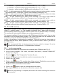
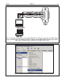
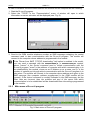
1
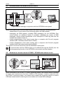
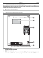
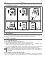
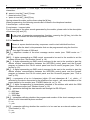
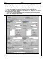
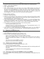
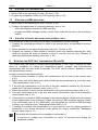
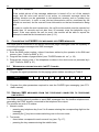
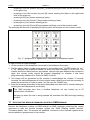
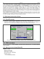
Communication module GSM LT-1 Firmware version 1.14 gsmLT-1_en 04/13 SATEL sp. z o.o. ul. Schuberta 79 80-172 Gdańsk POLAND tel. + 48 58 320 94 00 [email protected] www.satel.eu WARNINGS For safety reasons, the module should only be installed by qualified personnel. Prior to installation, please read carefully this manual in order to avoid mistakes that can lead to malfunction or even damage to the equipment. The module can only work in conjunction with PSTN subscriber lines. Changes, modifications or repairs not authorized by the manufacturer shall void your rights under the warranty. CAUTION! Never turn on power supply of the module and telephone without external antenna connected. Hereby, SATEL sp. z o.o., declares that this device is in compliance with the essential requirements and other relevant provisions of Directive 1999/5/EC. The declaration of conformity may be consulted at www.satel.eu/ce The SATEL's goal is to continually upgrade the quality of its products, which may result in alterations of their technical specifications and firmware. The current information on the introduced modifications is available on our website. Please visit us: http://www.satel.eu The following symbols may be used in this manual: - note; - caution. SATEL GSM LT-1 1 CONTENTS 1. 2. GSM LT-1 MODULE FEATURES .......................................................................................................... 2 TYPICAL MODULE APPLICATIONS ........................................................................................................ 2 2.1 INTEGRATION WITH INTEGRA CONTROL PANELS ......................................................................... 3 2.2 WORKING IN CONJUNCTION WITH STAM-1 / STAM-2 MONITORING STATION ................................. 3 2.3 WORKING IN CONJUNCTION WITH PBX STATIONS ......................................................................... 4 3. DESCRIPTION OF THE MODULE .......................................................................................................... 4 3.1 DESCRIPTION OF THE ELECTRONICS BOARD ................................................................................. 4 3.2 LED INDICATORS ........................................................................................................................ 5 4. INSTALLATION ................................................................................................................................... 6 5. PROGRAMMING ................................................................................................................................. 7 5.1 DTMF PROGRAMMING ................................................................................................................ 7 5.1.1 5.1.2 5.1.3 5.2 DLOAD10 PROGRAM ................................................................................................................. 12 5.2.1 5.2.2 5.2.3 5.2.4 5.2.5 5.2.6 5.2.7 5.2.8 5.2.9 5.2.10 6. 7. Programming mode.............................................................................................................................7 Starting a function and entering data ..................................................................................................7 Function list .........................................................................................................................................8 Local programming ...........................................................................................................................12 Remote programming .......................................................................................................................14 Main menu of DLOAD10 program ......................................................................................................15 Status bar ..........................................................................................................................................16 Changing the program access code .................................................................................................16 "GSM LT-1" tab .................................................................................................................................17 "Reporting" tab ..................................................................................................................................22 "TCP/IP downloading" tab.................................................................................................................26 "Firmware update" tab.......................................................................................................................27 "Events buffer" tab ............................................................................................................................28 REMOTE CONTROL BY MEANS OF SMS MESSAGE ............................................................................. 29 STARTING THE REPORTING .............................................................................................................. 29 7.1 STARTING THE GPRS REPORTING ............................................................................................. 30 7.1.1 7.1.2 Module test transmissions (GPRS)...................................................................................................30 Reporting events from the INTEGRA control panel (GPRS) ............................................................30 7.2 STARTING THE CSD REPORTING ............................................................................................... 31 7.3 STARTING THE SMS REPORTING ............................................................................................... 31 7.4 STARTING THE EVENT REPORTING OVER SEVERAL LINKS ............................................................ 31 8. STARTING THE CLIP TEST TRANSMISSION (DLOAD10)...................................................................... 31 9. CONVERTING THE PAGER TYPE MESSAGES INTO SMS MESSAGES .................................................. 32 9.1 WORKING IN CONJUNCTION WITH THE DT-1 DIALER .................................................................... 32 10. SENDING SMS MESSAGES FROM THE TELEPHONE CONNECTED TO TELEPHONE LINE OUTPUT ............ 32 11. INITIATING THE MODULE FIRMWARE UPDATE BY SMS MESSAGE ........................................................ 33 12. RESTORING THE FACTORY SETTINGS ............................................................................................... 34 12.1 DLOAD10 PROGRAM ................................................................................................................. 34 12.2 DTMF PROGRAMMING .............................................................................................................. 34 12.3 MODULE FACTORY SETTINGS (DLOAD10)................................................................................... 34 13. SPECIFICATIONS ............................................................................................................................. 35 2 GSM LT-1 SATEL 1. GSM LT-1 MODULE FEATURES Simulation of analog telephone line when using the GSM connection. Built-in industrial GSM telephone working in 850/900/1800/1900 MHz cellular telephony networks. Capability of remotely checking the status of available resources and the account validity of SIM card installed in the module. An output to signal the telephone line trouble and/or problem with logging into GSM network. Module control by means of SMS messages. Capability of determining the telephone numbers authorized for SMS control. Option to send test transmissions: in CLIP form; in form of event codes to the monitoring stations. Conversion and retransmission of event codes received through the RS-232 port from the INTEGRA alarm control panel. Several ways to send event codes to the monitoring station: GPRS transmissions (encrypted), CSD transmissions, SMS messages. Defining the priority of different ways to report events. Capability of storing up to 255 events generated by the module or received from the INTEGRA alarm control panel through the RS-232 port (modules with built-in GSM u-blox LEON-G100 telephone). Capability of converting the PAGER type text messages into SMS messages. Module programming: locally: landline telephone connected to the R-1 and T-1 terminals or computer with the DLOAD10 program installed, connected to the module RS-232 port; remotely: computer with the DLOAD10 program installed, connecting by means of GPRS. RS-232 port to allow: local programming by means of computer with the DLOAD10 program installed; connection to the alarm control panel or computer as an external modem; integration with the INTEGRA control panel; working in conjunction with the STAM-1 / STAM-2 monitoring station; updating the module firmware. Capability of remotely updating the module firmware by means of GPRS (modules with built-in GSM u-blox LEON-G100 telephone). Powered with 12 V DC (±15%). 2. TYPICAL MODULE APPLICATIONS The functionality of GSM module enables it to be used for a variety of applications. This section presents typical examples of its application. SATEL 2.1 GSM LT-1 3 INTEGRATION WITH INTEGRA CONTROL PANELS Fig. 1. Module working in conjunction with the INTEGRA control panel. When connected to the INTEGRA control panel, the module offers the following benefits: transmission of event codes to the monitoring station via GSM network; messaging via GSM network, including SMS messaging (for the INTEGRA Plus control panels, an additional feature is available: messaging by means of SMS messages, whose content corresponds to the description in event log and thus the installer does need to define it); remote programming of the control panel from a computer with DLOADX program installed (with a fast data transfer due to GPRS); remote management of the alarm system from a computer with GUARDX program installed (with a fast data transfer due to GPRS). The module can control connection with the INTEGRA control panel. If communication with the GSM module is to be effected through the RS-232 port, the local programming function in the INTEGRA control panel must be disabled. 2.2 WORKING IN CONJUNCTION WITH STAM-1 / STAM-2 MONITORING STATION Fig. 2. Module working in conjunction with the STAM-2 monitoring station. When connected to the STAM-1 / STAM-2 monitoring station, the module makes it possible to receive event codes sent in the form of SMS or CLIP message. If used in conjunction with the STAM-2 monitoring station, the module also enables the monitoring station to receive CSD data transmissions containing the event codes and to send SMS messages. 4 2.3 GSM LT-1 SATEL WORKING IN CONJUNCTION WITH PBX STATIONS The module can work in conjunction with the Private Branch Exchanges (PBX) as an additional external telephone line. It can be used to make outgoing calls to the mobile phone numbers and thus optimize the costs incurred. 3. 3.1 DESCRIPTION OF THE MODULE DESCRIPTION OF THE ELECTRONICS BOARD Fig. 3. View of GSM LT-1 module electronics board. Explanations for Fig. 3: 1 - external antenna connection. 2 - GSM industrial telephone. 3 - SIM card socket. It is not recommended that SIM card be inserted into the socket before the card PIN code has been programmed in the module. The GPRS service SATEL GSM LT-1 5 must be activated in the SIM card installed in the module, if the module is to use the functions requiring the GPRS technology. 4 - LEDs (see: section „LED indicators”): STAT LED indicate the module status, SIG LED indicate the level of antenna signal received by GSM telephone, TX and RX LEDs indicate that data are being transferred through the RS-232 port. 5 - RS-232 port. Description of the terminals: +12V – power supply input (12 V DC ±15%) GND – common ground FLT – OC type output to indicate a problem with login to the GSM network. It activates after about 10 minutes after occurrence of the problem. If active, it is shorted to the common ground. It remains shorted to the common ground until the cause of the trouble disappears. The problem with login to the GSM network may be caused by: – missing SIM card, – entered invalid PIN code, – missing or defective antenna, – non-availability of GSM service (out of range), – telephone defect. Detailed information about the trouble is provided by the on-board LED indicators (see: section „LED indicators”). The output can be connected to a control panel zone or it can directly control operation of the relay. R-1, T-1 – telephone line output (connection for alarm control panel, telephone set or another device provided with telephone dialer). When making a telephone call, the module changes the DC voltage polarization on telephone line output (T-1 and R-1 terminals), thus enabling individual charging of the phone calls. 3.2 LED INDICATORS Shown graphically below is how information is presented by the LED indicators. Each lighting scheme covers about 4 seconds and is repeated after 1 second pause ( – LED is OFF; – LED is ON). STAT indicates the module status: – (LED off) module power off, – normal operation of module, – no communication with GSM telephone, – invalid PIN code, – no PIN code, – no SIM card, – PUK code required, – PH-SIM PIN code required, – PIN2 code required, 6 GSM LT-1 SATEL – PUK2 code required, – SIM card busy, – module restart on switching power on, – SIM card damaged, – invalid SIM card, – other errors, – active connection. SIG indicates level of signal received by GSM telephone: – no GSM network signal, – level of signal 1, – level of signal 2, – level of signal 3, – level of signal 4. 4. INSTALLATION Disconnect power before making any electrical connections. It is not advisable to power up the device if the antenna is not connected. The GSM module should be installed indoors, in spaces with normal air humidity. The module power supply should have a sufficient output current and be provided with a battery. It is recommended that it be placed at a distance of 3 m or less from the module. When the supply voltage drops below 9.8 V, restart of the module occurs. The following installation procedure is recommended: 1. Connect the antenna to the on-board connector. If thick masonry walls, metal partitions etc. at the module installation place reduce the range of radio signal, use an antenna which can be installed at a location some distance from the module, where the correct level of GSM signal can be obtained. Do not install the antenna in parallel to the lowvoltage electrical installation wires, because this may cause interference. 2. Connect the control panel, telephone or another device equipped with telephone dialer to the R-1 and T-1 terminals. 3. Connect the power cables to the +12V and GND terminals. 4. Turn on power supply of the module. 5. Using the suitable function, enter the PIN code of SIM card (if required by the SIM card). 6. Turn off power supply of the module. 7. Insert the SIM card into the socket (see: Fig. 4). 8. Turn on power supply of the module. Logging the telephone into the GSM network may take a few minutes. If the SIM card PIN code is not programmed within 10 minutes of power-up, the telephone line voltage will be turned off. After the third attempt to use the wrong PIN code, the SIM card will be blocked. To unblock the SIM card, insert it into a mobile phone and enter the PUK code or use the function [16]. SATEL GSM LT-1 7 9. If the module is to be used as the external modem, connect the module RS-232 port to the suitable port of the device. 1 2 3 4 5 6 Fig. 4. Installing the SIM card. 5. PROGRAMMING You can configure the module using the keypad of telephone connected to the R-1 and T-1 terminals, or a computer with suitable software installed (locally and remotely). 5.1 DTMF PROGRAMMING 5.1.1 Programming mode In order to enter the module programming mode: 1. Take off-hook the telephone connected to the R-1 and T-1 terminals. 2. Using the telephone keypad, enter the following character string: [******xxxxxx******#], where "xxxxxx" is a six-digit access code (see: "Access code" p. 18). 3. Entry into the programming mode will be confirmed by the module with 4 short beeps followed by 1 long beep. It will remain in this mode until you put the phone on-hook. You can enter the module programming mode irrespective of the sounds which are currently produced in the telephone handset (e.g. the line busy tone, if the SIM card is not installed). 5.1.2 Starting a function and entering data In order to run a function, enter its number using the number keys, and then press twice the [*] key (see: "Function list"). Having started the function, you can use the keypad to program 8 GSM LT-1 SATEL the required parameters. To enter digits, use the number keys. You can also enter special characters: # - press in turn the [*] and [1] keys; * - press twice the [*] key; + - press in turn the [*] and [0] key. Having entered the data, confirm them using the [#] key. When programming, the following sounds can be heard in the telephone handset: 3 short beeps – correct data; 2 long beeps – incorrect data. For an overview of the other sounds generated by the module, please refer to the description of functions [14] and [15]. In the case of parameter programming functions, pressing the [#] key just after the function is started will reset the programmed values. 5.1.3 Function list Shown in square brackets are key sequences used to start individual functions. Shown after the dash is the parameter that can be programmed using the function. [01**] – four-digit PIN code of SIM card. [02**] – telephone number of the short message service center (see: "SMS center no. " p. 18). [03**] – 6 digits representing an SMS control command to be sent to the module to set the modem format (see: "Set modem format" p. 19). [04**] – 6 digits representing an SMS control command to be sent to the module to start the remote modem communication between the INTEGRA control panel and the DLOADX program or between the CA-64 control panel and the DLOAD64 program (see: "Call to service" p. 19). [05**] – 6 digits representing an SMS control command to be sent to the module to start the remote modem communication between the INTEGRA control panel and the GUARDX program or between the CA-64 control panel and the GUARD64 program (see: "Call to user" p. 20). [06**] – a sequence of up to 4 characters (digits: 0-9 and characters: #, *, +), which – if selected by the device connected to the telephone line output – will cause simulation of the pager station by the module (see: "PAGER station tel. no." p. 18). [08**] – 2 digits corresponding to transmission standard of the modem with which the GSM module communicates (see: "Modem format" p. 18). [09**] – parameter defining the data transfer rate through the RS-232 port: 0 – 4800 bps, 1 – 9600 bps, 2 – 19200 bps. [10**] – parameter defining whether the programmed number of the short message service center is a full international phone number: 0 – no, 1 – yes. [11**] – parameter defining whether the module is to be used as an external modem (see: "Fax/modem" p. 18): 0 – no, 1 – yes. SATEL GSM LT-1 9 [12**] – a six-digit access code, necessary to program the module using a telephone set. In the module with factory default settings, the 123456 value is programmed. The code can only be checked in the DLOAD10 program (see: "Access code" p. 18). [13**] – enter the digits 1234 and confirm using the [#] key to restore the factory settings (see: „Module factory settings ” p. 34). [14**] – on pressing the [#] key, the module will generate beeps (short – S, long – L) to indicate the level of signal received by the GSM antenna: LL – no GSM network signal, S – level of signal 1, SS – level of signal 2, SSS – level of signal 3, SSSS – level of signal 4. [15**] – on pressing the [#] key, the module will generate beeps (short – S, long – L) to indicate the module status: S – normal operation of module, SS – no communication with GSM telephone, SSS – invalid PIN code, SSSS – no PIN code, SSSSSSSS – no SIM card, SL – PUK code required, SSL – PH-SIM PIN code required, SSSL – PIN2 code required, SSSSL – PUK2 code required, LlSs (beeps of decreasing duration) – SIM card busy, LL – module restart on switching power on, LLL – SIM card damaged, LSLS – invalid SIM card, LSSSL – other errors. [16**] – eight-digit PUK code of the SIM card. If correct, the code will be confirmed after several seconds by 3 short beeps (SSS). The function is only available, if the SIM card is blocked. The module will indicate blocking of the SIM card by means of the STAT LED or beeps in the handset of telephone connected to the phone line output. Entering the PUK code into the module will unblock the SIM card and change its PIN code to that currently stored in the module memory. Before entering the PUK code, make sure that the programmed PIN code is correct. If no PIN code of SIM card has been saved to the module settings, the PUK code will not be accepted. [17**] – parameter defining whether voltage at the phone line terminals is to be switched off in case of a GSM phone trouble: 0 – no, 1 – yes. [18**] – parameter defining whether establishing a connection is to be indicated by sound signal: 0 – no, 1 – yes. [19**] – parameter defining the test transmission period: 0 – no test transmission, 1 – 2 h 58 min, 10 GSM LT-1 SATEL 2 – 5 h 57 min, 3 – 11 h 56 min, 4 – 23 h 55 min, 5 – 2 d 23 h 53 min, 6 – 6 d 23 h 30 min. Having entered the parameter, you can either confirm it at once with the [#] key or enter the next parameter to define whether the first test transmission is to be performed at a time randomly selected by the module: 0 – no, 1 – yes. [20**] – parameter defining whether the module test transmission is to have a priority (see: "Messaging priority" p. 21): 0 – no, 1 – yes. [21**] … [24**] – telephone number to which the module will be able to send CLIP test transmissions ([21] – 1. phone number; [22] – 2. phone number; [23] – 3. phone number; [24] – 4. phone number). You can enter from 1 to 16 characters (digits: 0-9 and characters: #, *, +). It is recommended that the phone number be preceded by the country code. [25**] – 6 digits (ddhhmm) defining the test transmission period. You can program up to 31 days 23 hrs 59 min. Values 00 mean no test transmission. Having entered 6 digits, you can either confirm them at once using the [#] key or enter a seventh digit to define whether the first test transmission is to be performed at a time randomly selected by the module (see: "Test transmission every" p. 21): 0 – no, 1 – yes. [26**] – telephone number to which the module will send confirmation of a change in module settings, received in the SMS message (see: "Send SMS on change to" p. 20). You can enter from 1 to 16 characters (digits: 0-9 and characters: #, *, +). The entered phone number must be preceded by the country code. [27**] – 6 digits representing the SMS control command to be sent to module to program the test transmission period (see: "Change test period" p. 20). [28**] … [31**] – in each function you have to program 6 digits representing the SMS control command to be sent to the module to program the phone number for test transmissions ([28] – 1. phone number; [29] – 2. phone number; [30] – 3. phone number; [31] – 4. phone number; see also: "Change tel. 1–4" p. 20). [32**] … [35**] – number of test transmission retries ([32] – for 1. phone number; [33] – for 2. phone number; [34] – for 3. phone number; [35] – for 4. phone number). You can program values from 1 to 15. [36**] … [39**] – parameter defining whether the test transmission sent by the module ([36] – to 1. phone number; [37] – to 2. phone number; [38] – to 3. phone number; [39] – to 4. phone number; see also: p. 21 and "Send SMS on change to" p. 20) is to be confirmed: 0 – no, 1 – yes, 2 – yes, and if there is no confirmation an SMS will be sent. [40**] – parameter defining whether the content of SMS message to be sent if there is no test transmission receipt confirmation is to be a default one: 0 – no (SMS message content will be as defined by means of the DLOAD10 program), 1 – yes (SMS message will contain the "CLIP failed" information). SATEL GSM LT-1 11 [41**] – a sequence of up to 4 digits which will replace the "+" character in the phone number from which the CLIP connection is established to the module. [97**] – parameter defining whether the module is to execute the reporting function: 0 – no, 1 – yes. [98**] – parameter defining whether the module is to monitor the status of connection with INTEGRA control panel through the RS-232 port: 0 – no, 1 – yes. The connection will be monitored for the INTEGRA control panel version 1.06 or later. [99**] – parameter defining whether the module is to answer to CLIP (see: "CLIP answering" p. 21): 0 – no, 1 – yes. [99**] – enter the digits 7890 and confirm with the [#] key to start the module test mode. It allows you to check the LEDs on the module electronics board for proper functioning. After the test mode is started, the LEDs will go off. Then, each of them (in order: STAT, SIG, TX, RX) will light up for about 1 second and the FLT output will activate. When the LED testing procedure is finished, the module will return to the state from before starting the test mode. [105**] – parameter defining the number of unsuccessful attempts to send the event through the given reporting channel, after which the module will attempt to send the event through the next channel. You can program values from 2 to 255 (default: 3). [111**] – a sequence of 4 characters defining which GSM frequencies are to be used by the GSM phone installed in the module (the parameter refers to the modules with u-blox LEON-G100 GSM phone): 1. character – 850 MHz (0 – no; 1 – yes); 2. character – 900 MHz (0 – no; 1 – yes); 3. character – 1800 MHz (0 – no; 1 – yes); 4. character – 1900 MHz (0 – no; 1 – yes). You can select any band combination. If you select all four or none, the module will interpret it as all frequencies being available and will select the most suitable one(s). [112**] – 6 digits representing the SMS control command to be sent to module to restart it. [113**] – parameter defining the time after which the module, if not used, will restart the phone (see: "Autorestart every" p. 22). You can enter from 1 to 25 hours. [114**] – a sequence of up to 8 characters (digits: 0-9 and characters: #, *, +) defining the country code, which should be programmed, if the PAGER type cellular phone numbers to be notified in the control panel are not preceded by it. [115**] – parameter defining whether the SMS and DTMF control can be executed: 0 – from any phone number, 1 – from authorized phone numbers only (see: "SMS control only from list of messaging tel. numbers" p. 20). [116**] – a sequence of 5 characters defining the phone numbers to which the module is to send the received SMS messages: 1. character – 1. phone number for test transmission (0 – no; 1 – yes); 2. character – 2. phone number for test transmission (0 – no; 1 – yes); 12 GSM LT-1 SATEL 3. character – 3. phone number for test transmission (0 – no; 1 – yes); 4. character – 4. phone number for test transmission (0 – no; 1 – yes); 5. character – phone number for SMS control confirmation (0 – no; 1 – yes). [117**] – 6 digits representing the SMS control command to be sent to the module to transfer the network codes – USSD (see: "USSD codes forwarding message" p. 22). [118**] – 6 digits representing the SMS control command to be sent to the module to initiate the firmware update process (see: "SMS initiating update" p. 27). [119**] – 6 digits representing the SMS control command to be sent to the module to establish communication with the DLOAD10 program (see: "Initiating SMS" p. 26). [120**] – 6 digits representing the SMS control command to be sent to the module to establish communication with the DLOADX program (see: "Initiating SMS" p. 26). [121**] – 6 digits representing the SMS control command to be sent to the module to establish communication with the GUARDX program (see: "Initiating SMS" p. 27). 5.2 DLOAD10 PROGRAM The DLOAD10 program version 1.00.039 is required for programming and configuration of the GSM LT-1 module version 1.14. The program is delivered free of charge with the device. Communication between the program and the module can be effected locally or remotely. The module with factory default settings can only be programmed locally. The program installation file can be found on the CD delivered with the module. You can also download it from the www.satel.eu website. The DLOAD10 program can be installed on the computers running the Windows XP/VISTA/7 operating system. Access to the program is protected with a password. During its first start-up, the program is accessed with the factory default password: 1234 (you do not need to enter it, just click on the "OK" button). It is recommended that the factory password (access code) be changed. It can be replaced with any sequence of 16 alphanumeric characters. 5.2.1 Local programming 1. Connect the module RS-232 port with the computer serial COM port (see: Fig. 5). 2. In the DLOAD10 program, "File" menu, first select "New device", and then "GSM-4/5/LT module" (see: Fig. 6). key. The "Configuration" window will open. 3. Press the 4. Indicate the computer port to which the module is connected (see: Fig. 7). 5. Click on the "OK" button. 6. Click on the button. The module data will be read out. Establishing communication will be indicated in the program window by a suitable message. 7. Program suitable parameters for the module. button to write the entered data to the module. 8. Click on the 9. The programmed data can be saved as a file to the computer disk. When the programming is completed, disconnect the cable connecting the module to the computer. SATEL GSM LT-1 13 Fig. 5. Computer connection to the module RS-232 port. Shown on the left is the PIN-5 plug to be connected into the module connector. Shown on the right is DB-9 female plug (solder side view). A ready cable is offered in the DB9F/RJ-KPL set. Fig. 6. Selecting the GSM module after starting the DLOAD10 program. 14 GSM LT-1 SATEL Fig. 7. "Configuration" window. 5.2.2 Remote programming During remote programming, the module will not execute any other functions requiring the use of GSM telephone. Most of the parameters required for remote programming of the module can only be programmed using the DLOAD10 program. The remote programming is available after the following items have been programmed: in the "GSM LT-1" tab: PIN code of the SIM card (if PIN code is required by the card); access point name (APN) for the Internet GPRS connection ("GPRS APN" field); DNS server IP address ("DNS server" field) to be used by the module (you do not need to program the DNS server address, if the computer address will be entered as an IP address, not a name); user name for the Internet GPRS connection ("Username" field); password for the Internet GPRS connection ("Password" field); in the "Downloading TCP/IP" tab: the control command that initiate connection with the computer ("Initiating SMS" field); address of the computer from which the module is to be remotely programmed ("Server address" field); whether the module can connect to the computer whose address will be given in the SMS message ("Server from SMS" option); number of the port through which communication between computer and module is to be effected; DLOAD10 key. The computer running the DLOAD10 program must have the so-called public address (that can be seen directly in the Internet by everybody). SATEL GSM LT-1 15 In order to establish communication between the module and the computer do the following: 1. Start the DLOAD10 program. 2. Select the "TCP/IP" in the "Communication" menu. A window will open in which information on server activation will be displayed (see: Fig. 8). Fig. 8. "TCP/IP" window. 3. Send to the GSM module telephone number an SMS message containing the control command used to start communication with the DLOAD10 program. The module will connect to the computer whose address is programmed in the module. If the "Server from SMS" ("TCP/IP downloading" tab) option is enabled in the modul, you can send a message with the xxxxxx=aaaa:p. or xxxxxx=aaaa:p= content, where "xxxxxx" is the control command used to initiate communication with the DLOAD10 program, "aaaa" is the address of computer with which communication is to be established by the module, shown as an IP address or as a name, and "p" is the number of network port through which communication with the DLOAD10 program is to take place. The module will connect to the computer whose address was given in the SMS message (the computer address programmed in the GSM module will be ignored). If the control command is correctly indicated in the SMS message, but the other data are incorrect, then the address and port of the server with which communication is to be established will be downloaded from the settings programmed in the module. 5.2.3 Main menu of DLOAD10 program Fig. 9. Main menu of DLOAD10 program. 16 GSM LT-1 SATEL Explanations for Fig. 9: 1 - GSM module type. 2 - module firmware version (version number and build date). 3 - information on the status of communication between module and program. 4 - time and date according to the module clock. When logging into the network, the module updates these data automatically, if the operator whose services are used by the module offers such a function. 5 - information on the GSM telephone status. 6 - level of signal received by the GSM antenna. Buttons: Events – button opens the "Events buffer" tab. Read – button allows reading data from the module. Write – button allows writing data to the module. Quit transmission – button makes it possible to cancel the data reading/writing. Event log read – button allows reading the event log. Configuration – button opens the "Configuration" window. Exit – button closes the program. 5.2.4 Status bar Fig. 10. Status bar in DLOAD10 program. Explanations for Figure 10: 1 - icon indicating the status of communication with the module: – green color – ready to send data; – alternating green and yellow color – data transmission in progress; – gray color – COM port disabled. A click on the icon button in case of communication via the RS-232 port – will enable/disable the COM port. 2 - information on way of communication with the module: – COMn (n = COM port number) – communication through the RS-232 port; – TCP/IP – communication using the GPRS technology. 5.2.5 Changing the program access code 1. In the "File" menu, select "Configuration", and then "Change access code" (see: Fig. 11). SATEL GSM LT-1 17 Fig. 11. Functions related to the DLOAD10 program access. 2. Enter the old access code and click on the "OK" button 3. Enter the new access code and click on the "OK" button. 4. Enter again the new access code and click on the "OK" button. The program allows to get access based on additional codes which can be programmed and for which authority level can be defined (in the "File" menu, select "Configuration", and then "Dload10 users" – see: Fig. 11). 5.2.6 "GSM LT-1" tab Shown in square brackets are the numbers of functions for the DTMF programming mode. Fig. 12. "GSM LT-1" tab. 18 GSM LT-1 SATEL PIN code [01] – PIN code of SIM card. Entering a wrong code may result in blocking the SIM card. SMS center no. [02] – telephone number of the short message service center (up to 16 characters). If the number has been written by the operator to the memory of SIM card installed in the device, it need not be entered. In such a situation, the module will download it automatically. Otherwise, it is necessary to enter the number, if the module is to send SMS messages. It should be remembered that the number written into the module must be suitable for the network in which the SIM card is registered. Full, international number [10] – if this option is enabled, the SMS center number must be entered as an international number (i.e. including the country code). Fax/modem [11] – if this option is enabled, the module can be used as an external modem. The module starts working in the modem mode on receiving the AT command, and stops working in this mode when the DTR signal is lost. Do not enable the "Fax/modem" option, if the module is working in conjunction with the INTEGRA control panel (the control panel is connected to the module RS-232 port). Modem format [08] – the transmission standard of the modem with which the GSM module communicates. The format code is to be entered as 2 digits, according to the table below. modem format for GSM u-blox LEON-G100 telephone 00 auto 04 2400 bps V.22bis 05 2400 bps V.26ter 06 4800 bps V.32 07 9600 bps V.32 12 9600 bps V.34 68 2400 bps V.110/X.31 flag stuffing 70 4800 bps V.110/X.31 flag stuffing 71 9600 bps V.110/X.31 flag stuffing Table 1. Modem format codes for the GSM u-blox LEON-G100 telephone. format code Access code [12] – a sequence of 6 alphanumeric characters starting the local DTMF programming function. Entering the sequence from the keypad of telephone connected to the phone line output will enable you to define the module settings. In the module with factory default settings, the value 123456 is preprogrammed. You will be able to see the value when you click on the button. If you delete the access code and quit the local programming mode, any next changes in the settings, including the code restoration, will only be possible by means of the DLOAD10 program. RS-232 baud rate [09] – the rate of data transfer through the RS-232 port. PAGER station tel. no. [06] – the number after dialing of which by a device connected to the telephone line output the module will simulate the pager station. The further part of the dialed number will be treated as the cellular telephone number to which the PAGER type message will be sent in the form of SMS message. The pager station number can consist of up to 4 characters. The programmed number must be unique and must not coincide with any other number programmed in the module. GPRS APN – access point name for Internet GPRS connection. SATEL GSM LT-1 19 DNS server – IP address of DNS server to be used by the module. It is necessary for GPRS communication, when the address of device to which the control panel is to connect (monitoring station, computer with DLOAD10 program) has been entered in the form of a name. If all addresses are entered in the form of an IP address (4 decimal numbers, separated by dots), the DNS server address need not be programmed. User – user name for Internet GPRS connection. Password – password for Internet GPRS connection. The GPRS parameters can only be programmed using the DLOAD10 program. APN, user name and password have to be programmed, if the data transfer using GPRS technology technologii (event codes, programming) is to be available. GSM band [111] – the frequency bands which are to be supported by the GSM phone (the parameter applies to modules with GSM u-blox LEON-G100 telephone). There are the following bands to choose from: 850 MHz, 900 MHz, 1800 MHz, 1900 MHz. You can select any number of bands. If all or none of them are selected, the module will recognize that all frequencies are available and will choose the most suitable one(s). SMS control – the module can be remotely controlled by means of SMS messages containing the suitable control command. You can program the control commands after receiving of which the module will: change modem format [03]; initiate modem communication between INTEGRA / CA-64 control panel and DLOADX / DLOAD64 program [04]; initiate modem communication between INTEGRA / CA-64 control panel and GUARDX / GUARD64 program [05]; be restarted [112]; program the test transmission period [27]; program the phone numbers for test transmissions [28]…[31]. The control command may have any content, but it must consist of six alphanumeric characters. The control commands may not contain any diacritical marks. You can use a space character in the control command content, but at least one of the characters must be different from the space character. Set modem format [03] The SMS message sent to the module to set the modem format must have the following form: xxxxxx=yy, where "xxxxxx" is the control command and "yy" is the modem format code (see Table 1 p. 18). Having received such an SMS message, the module will change the modem format Call to service [04] The control command can start the remote modem communication between the INTEGRA control panel and the DLOADX program, or between the CA-64 control panel 20 GSM LT-1 SATEL and the DLOAD64 program (this applies to the CA-64 control panel firmware version 1.04.03 or newer, and the DLOAD64 program version 1.04.04 or newer). The SMS message sent to the module may have the following form: xxxxxx=yyyy. or xxxxxx=yyyy=, where "xxxxxx" is the control command and "yyyy" is the computer telephone number with which the control panel is to establish communication. If no telephone number is given, the control panel will connect to the number programmed in its memory. If the module receives an SMS message initiating connection with the INTEGRA control panel, and the access to DLOADX program is blocked, the module will send an appropriate SMS message to the telephone number programmed using the "Send SMS on change to" function (see: p. 20). Call to user [05] The control command can start the remote modem communication between the INTEGRA control panel and the GUARDX program, or between the CA-64 control panel and the GUARD64 program (this applies to the CA-64 control panel firmware version 1.04.03 or newer, and the GUARD64 program version 1.04.04 or newer). The SMS message sent to the module may have the following form: xxxxxx=yyyy. or xxxxxx=yyyy=, where "xxxxxx" is the control command and "yyyy" is the computer telephone number with which the control panel is to establish communication. If no telephone number is given, the control panel will connect to the number programmed in its memory. Change test period [27] Using the control command, you can program the test transmission period. The SMS message to be sent to the module must have the following form: "xxxxxx=P", where "xxxxxx" is the control command, and "P" is the test transmission period: 0 – no test transmission, 1 – 2 h 58 min, 2 – 5 h 57 min, 3 – 11 h 56 min, 4 – 23 h 55 min, 5 – 2 d 23 h 53 min, 6 – 6 d 23 h 30 min. Change tel. 1–4 [28]…[31] Using the control command, you can program the phone numbers for test transmissions. The SMS message sent to the module must have the following form: "xxxxxx=yyyy." or "xxxxxx=yyyy=", where "xxxxxx" is the control command and "yyyy" is the new telephone number for test transmissions. It is recommended that the telephone number be preceded by the country code. Send SMS on change to [26] – phone number to which the module will send confirmation of execution of the control command (changing the modem format, programming the test transmission period, programming the phone numbers for test transmissions) received in the SMS message. The message sent by the module will contain information on the current module state (see: "Remote control by means of SMS message" p. 29). The entered phone number must be preceded by the country code. SMS control only from list of messaging tel. numbers [115] – if this option is enabled, the SMS and DTMF control is possible from the telephone whose number is: one of the numbers to which the test transmission is sent (see: p. 21), number to which the SMS message confirming the module setting change received in the SMS message is sent (see: "Send SMS on change to" p. 20), SATEL GSM LT-1 21 the number to which the SMS message is sent, if the module fails to send the event code to the monitoring station (see: "Tel. number" p. 25). No voltage on T-1/R-1 if GSM trouble [17] – if this option is enabled, voltage on the telephone line terminals will be turned off in case of the GSM telephone trouble. Generate routing signal [18] – if the option is enabled, the connection setup is audibly signaled. Messaging priority [20] – if the option is enabled and a telephone connection of the device connected to the line output is going on, and the module will have to send a test transmission, the connection will be terminated. If this option is disabled, test transmission will only be realized when the device connected to the telephone line output completes the call. Convert "+" to digits [41] – the digits to which the "+" character will be changed in the telephone number, from which a CLIP connection is established with the module number. CLIP answering [99] – the module offers the CLIP answering feature, which enables its operation to be monitored. The following options are available: n/a – no answer, CLIP – answer in the CLIP form. Test transmissions – the module can send test transmissions to four phone numbers, for which the following parameters should be defined: phone number [21]…[24] – it is recommended that the number be preceded by the country code. number of retries of the test transmission to the given phone number [32]…[35] – you can program values from 1 to 15. confirmation control option, parameter 1 [36]…[39] – if this option is enabled, receiving the test transmission by the given phone is to be confirmed. In order to confirm the receipt of test transmission, you must reject the module call not earlier than 10 seconds and not later than 20 seconds of hearing the ring in the phone. The confirmation of test transmission receipt will make the module stop repeating the call. If the confirmation control option is disabled, the module will only establish one connection, irrespective of the programmed number of retries. option of SMS message sending if there is no confirmation, parameter 2 [36]…[39] – if this option is enabled, lack of receipt of the test transmission will result in sending an SMS message with content entered in the "Messaging trouble SMS" field to the given phone number. Test transmission every [19] / [25] – the module test transmission can be effected using the CLIP service or sent as the event code to the monitoring station. If the test transmission is to be of periodical nature, you have to program every how many days, hours and minutes it is to be sent. The first test transmission will be sent after approximately 30 seconds of saving the settings to the module, and the next one – after expiry of the programmed time. Up to 31 days 23 hours 59 minutes can be programmed. The values 00 mean there will be no test transmission. Messaging trouble SMS [40] – content of the SMS message, which will be sent in case of a failed test transmission. The message can contain up to 32 characters. First period random [19] / [25] – if this option is enabled, the first test transmission will be made at a time randomly selected by the module. The next transmissions will take place according to the period programmed using the "Test transmission every" function. Prefix for SMS [114] – the country code which must be programmed, if they not precede the cellular phone numbers for PAGER type messaging in the control panel. 22 GSM LT-1 SATEL Autorestart every [113] – you can program the time period after which the module, if not used, will restart the telephone. From 1 to 25 hours can be entered. The "use" of the module shall be understood as: receiving the module outgoing call, occurrence of the incoming call signal, receiving acknowledgement of an SMS message sent by the module, receiving an SMS message, sending data by the module working as an external modem. The first telephone restart will take place after the programmed time elapsed from saving the settings to module. USSD codes forwarding message [117] – the control command which must precede the USSD code in the SMS message sent to the module. The USSD codes enable you e.g. to check the account status of SIM card installed in the module. The SMS message sent to the module must have the following form: "xxxxxx=yyyy." or "xxxxxx=yyyy=", where "xxxxxx" is the control command and "yyyy" is the USSD code supported by the operator of GSM network in which the telephone operates (it depends on the SIM card installed in the module). Having received such an SMS message, the module will execute the USSD code contained in it. The answer obtained from the operator is forwarded in the form of SMS message to the telephone number from which the control command was sent. It is not advisable to use the advanced functions available due to the USSD service if menu is presented in response to the entered code. Transfer unknown SMS [116] – the module can forward the received unknown SMS messages (e.g. information received from the GSM provider) to: phone numbers to which test transmissions are sent (see: p. 21), phone number to which an SMS message is sent to confirm the change in module settings received in SMS message (see: "Send SMS on change to" p. 20). The message content is preceded by the telephone number from which it was sent. For the modules with built-in GSM u-blox LEON-G100 telephone, the message content will be sent in the form of 2 messages, if it contains more than 160 characters, including the message number. For the modules with built-in other telephone model, up to 64 first characters of the received message can be sent. 5.2.7 "Reporting" tab Most of the parameters necessary to execute the reporting function can only be programmed using the DLOAD10 program. For further reporting related information, please refer to section "Starting the reporting" p. 29. Configuring the reporting Reporting [97] – if this option is enabled, the module can report to monitoring station. For the modules with built-in industrial-type GSM telephone other than the u-blox LEON-G100 telephone, enabling the reporting feature will disable the feature of PAGER message conversion into SMS messages. INTEGRA presence supervision [98] – if this option is enabled, the status of connection with INTEGRA control panel through RS-232 port is monitored. If loss of connection is found, the module can report it to the monitoring station. The connection will be monitored for the INTEGRA control panel version 1.06 or later. SATEL GSM LT-1 23 Events buffering – the option is available in the module with built-in GSM u-blox LEON-G100 telephone. It refers to the events received from the INTEGRA control panel through the RS-232 port and the test transmissions sent by the module to the monitoring stations. If the option is enabled: each event received from the control panel is acknowledged at once, events are recorded in the event log (see: section "Events buffer" tab p. 28). If the option is disabled, depending on the reporting link, receipt of the event is acknowledged to the control panel by: GPRS / CSD – after acknowledgement of the event receipt by the monitoring station; SMS – after sending the SMS message. Fig. 13. "Reporting" tab. 24 GSM LT-1 SATEL Reporting test send all media – if this option is enabled, the module test transmission is sent over all links which have been programmed using the "Priority" function. If the "Events buffering" option is enabled and the test transmission is sent over all links, the "Events buffer" tab will only display the event communicating information about test transmission sent over the reporting link programmed as the last one. Number of reporting retries before sending other way [105] – the number of unsuccessful retries to send the event over the given reporting link, after which the module will make an attempt to send the event over the next link. You can program values from 2 to 255 (by default: 3). Reporting station 1 / 2 Station addr. – network address of the monitoring station. It can be entered as an IP address (4 decimal numbers separated by dots) or as a name. Port – the number of TCP port on which transmission of events to the monitoring station will take place. The port number must be consistent with that programmed in the monitoring station. Station key – a sequence of up to 12 alphanumeric characters (digits, letters and special characters) defining the key with which the data sent to the monitoring station will be encrypted. It must be consistent with that programmed in the monitoring station. System identifier – 4 characters (digits or letters from A to F), used to identify the module. They must be programmed, if the module is to send test transmissions, or in case of GPRS reporting. The value 0000, which is entered by default, means no identifier. GPRS key – a sequence of up to 5 alphanumeric characters to identify the module. It must be consistent with that programmed in the monitoring station ("ETHM / GPRS key"). Priority In order to add a reporting link: 1. Press the "Add" button. A drop-down menu with available reporting links will be displayed. 2. Click on the selected reporting link. It will be displayed on the list. 3. Proceed in the same way to select next reporting links. In order to delete a programmed link: 1. Highlight in the list the selected reporting link which is to be removed. 2. Press the "Remove" button. In order to change the reporting link priority: 1. Click on the selected reporting link on the list. 2. If it is to be moved one position up, press the 3. If it is to be moved one position down, press the button. button. If the module fails to send an event to the selected monitoring station over all the programmed links in turn, it will restart the reporting procedure after 2.5 minutes. If more than one reporting link is selected for the given monitoring station and the event has been successfully sent over a link which is not the first on the list, and the module is to send a next event within less than 7.5 minutes, the event will be sent over the same link. The module will make an attempt to send events, SATEL GSM LT-1 25 starting from the first reporting link on the list, only after 7.5 minutes have elapsed since sending the last event. Telephone numbers CDS reporting – the telephone number to which events are reported using the CSD technology. It must be preceded by the country code. The CSD data transmission service is usually available in the basic package of services offered by the mobile network operator, however before programming suitable parameters you must make sure if it is possible to use it. SMS reporting – the telephone number to which events are reported using the SMS messages. It must be preceded by the country code. SMS format The SMS message format for SMS reporting must be entered, as required by the monitoring station. The SMS message format programmed by default in the module corresponds to the default settings of STAM-2 monitoring station (program version 1.2.0 or newer). If the events are to be sent in the 4/2 format, only identifier and event code zone symbol). Question marks will be sent instead of the are sent (instead of the other special characters of the format. Reporting trouble messaging Send SMS – the content of SMS message which will be sent if the "Events buffering" option is enabled and the module fails to send the event to the selected monitoring station. The message can contain up to 32 characters. Tel. number – the telephone number to which SMS message will be sent if the module fails to send the event to the selected monitoring station. Events The module can send the test transmission in the form of event code to the monitoring station. In the DLOAD10 program, the following parameters should be programmed for each event: S1 – check the field, if the event is to be sent to the monitoring station 1. Double click to check / uncheck the field. S2 – check the field, if the event is to be sent to the monitoring station 2. Double click to check / uncheck the field. Format – the format in which the event code will be sent. Double click to select: 4/2 (Ademco Express) or CID (Contact ID). CODE – the event code which will be sent to the monitoring station. For the 4/2 format, 2 characters are to be programmed (digits or letters from A to F), and for Contact ID – 3 digits. In the case of Contact ID format, you can use the code editor. To open the window of code editor, click on the button available in the event description field. R – the event qualifier for Contact ID format, which defines whether it is new event or restore. Double click to check / uncheck the field. If the field is checked, the restore code is sent. Part. – partition number (refers to Contact ID format). No. – number of zone / expander / user (refers to Contact ID format). Event description – the field used for the Contact ID format. It displays description of the event whose code is entered in the "CODE" field. Additionally, the button for opening the Contact ID code editor is available in the field. 26 5.2.8 GSM LT-1 SATEL "TCP/IP downloading" tab Fig. 14. "TCP/IP downloading" tab. Most of the parameters required for correct communication between the module and the DLOAD10, DLOADX and GUARDX programs using the GPRS technology can only be programmed by means of the DLOAD10 program. Communication over TCP/IP Server address – address of the computer from which the module can be remotely programmed. It can be entered as an IP address or as a name. Server from SMS – if this option is enabled, the address of server, to which the module is to connect, and the port number can be entered in the content of SMS message initiating the connection. If the address is not entered, the module will connect to the server whose address has been programmed in the module. Port – the number of port on which the communication between computer and module will take place. Initiating SMS [119] – the control command that must be included in the SMS message sent to the telephone number of GSM module, so that the module can start the procedure of establishing communication with the DLOAD10 program (communication using the GPRS technology). Dload10 key – the string of 12 alphanumeric characters (digits, letters and special characters) defining the key with which the data sent to the DLOAD10 program will be encrypted. The module will only establish connection to the program using the correct key. Communication Integra-DloadX Server address – the address of computer with the DLOADX program, with which the module (connected to the INTEGRA control panel through RS-232 port) is to communicate using the GPRS technology. It can be entered as an IP address or as a name. Server from SMS – if this option is enabled, the address of server, to which the module is to connect, and the port number can be entered in the content of SMS message initiating the connection. If the address is not entered, the module will connect to the computer whose address has been programmed in the module. Port – the number of port on which the communication with the DLOADX program will take place. Initiating SMS [120] – the control command that must be included in the SMS message sent to the telephone number of GSM module connected to the control panel, so that the module can establish communication with the DLOADX program using the GPRS technology. SATEL GSM LT-1 27 DloadX key – the string of 12 alphanumeric characters (digits, letters and special characters) defining the key with which the data sent to the DLOADX program will be encrypted. The module will only establish connection to the program using the correct key. encrypted transmission – if this option is enabled, the data transmission between module and program will be encrypted. The option must be enabled. Communication Integra-GuardX Server address – the address of computer with the GUARDX program, with which the module (connected to the INTEGRA control panel through RS-232 port) is to communicate using the GPRS technology. It can be entered as an IP address or as a name. Server from SMS – if this option is enabled, the address of server, to which the module is to connect, and the port number can be entered in the content of SMS message initiating the connection. If the address is not entered, the module will connect to the computer whose address has been programmed in the module. Port – the number of port on which the communication with the GUARDX program will take place. Initiating SMS [121] – the control command that must be included in the SMS message sent to the telephone number of GSM module connected to the control panel, so that the module can establish communication with the GUARDX program using the GPRS technology. GuardX key – the string of 12 alphanumeric characters (digits, letters and special characters) defining the key with which the data sent to the GUARDX program will be encrypted. The module will only establish connection to the program using the correct key. 5.2.9 "Firmware update" tab Fig. 15. "Firmware update" tab. The values shown are only an example. Remote update of the module firmware by means of GPRS is possible for modules with the u-blox LEON-G100 industrial GSM telephone. Most of the parameters required to initiate the firmware update process can only be programmed by means of the DLOAD10 program. For information on the firmware update server please visit the www.satel.eu site. Update server – the address of server to which the module is to connect for firmware update. It can be entered as an IP address or as a name. Port – the number of server port shown in the form of decimal numbers. SMS initiating update [118] – the control command that must be included in the SMS message sent to the telephone number of GSM module so as to initiate the firmware update. 28 GSM LT-1 SATEL Server from SMS – if this option is enabled, the address of server, to which the module is to connect, and the port number can be entered in the content of SMS message initiating the connection. If the address is not entered, the module will connect to the server whose address has been programmed in the module. Check for updates after every reboot – if this option is enabled, the module will connect to the firmware update server after each restart to check whether a new firmware is available. every… days – if the module is to periodically check for updates, you must indicate every how many days it is to take place. You can program up to 31 days. The value 0 means that that module will not periodically connect to the firmware update server. SMS messages Update successful – the SMS message which will be sent after successful update of module firmware. No newer firmware – the SMS message which will be sent after the module has checked that there is no newer firmware for the module. Update failed – the SMS message which will be sent after a failed attempt of module firmware update. The SMS messages that informs about the update result may contain up to 32 characters. 5.2.10 "Events buffer" tab Fig. 16. "Events buffer" tab. The module with built-in u-blox LEON-G100 GSM telephone has a non-volatile memory recording up to 255 events. The events are saved to memory and the "Events buffer" tab is available, if the events buffering option is enabled (see: "Events buffering" p. 23). SATEL GSM LT-1 29 The events are presented in the descending order (the newest at top, the oldest at bottom). The individual columns show the following information: Received – the date when event was received by the module. Send – the date when event was sent by the module to the monitoring station. S1 / S2 – reporting status (S1 – monitoring station 1, S2 – monitoring station 2): --- – the event is not reported, . – the event is waiting to be reported, name of reporting link – the event was sent successfully to the monitoring station over the indicated link. Event code Description – event description (for events in Contact ID format). Refresh – use this button to download events from the module. 6. REMOTE CONTROL BY MEANS OF SMS MESSAGE Program the control commands (see: section: "SMS control" p. 19). If the control availability is to be limited to the telephones whose numbers have been programmed in the module (see: p. 21, "Send SMS on change to" p. 20 and "Tel. number" p. 25) – enable the "SMS control only from list of messaging tel. numbers" option (see: p. 20); If module is to confirm execution of the control command by means of SMS message, program the following items: telephone number to which acknowledgements will be sent by the module (see: "Send SMS on change to" p. 20); SMS center number (see: "SMS center no." p. 18). To use the control: 1. Send the SMS message containing a control command to the telephone number of GSM module. The control command may be just a fragment of the SMS message, but it must be among the first 32 characters. This makes it is possible to write the control command, including the comments, to the telephone memory and send the whole to the module. 2. After execution of the command, the module will send an SMS message, which can have the following form: "SIG=?, Test: ??d??h??m T1=?...? T2=?...? T3=?...? T4=?...?" where: SIG – actual level of signal received by antenna [digits from 0 to 4]. Test – information on the time interval at which the test transmission will be sent [currently programmed number of days (d), hours (h) and minutes (m)]. T1 ÷ T4 – information on the telephone numbers programmed in the module (phone numbers to which the test transmissions can be sent). 7. STARTING THE REPORTING The module can send to the monitoring station the following event codes: generated by the module (test transmission); received from the INTEGRA control panel through the RS-232 port. 30 GSM LT-1 SATEL The module offers the following forms of event code sending to the monitoring station: GPRS – packet data transmission. CSD – data transmission. SMS – SMS messages. If the event code is sent using an SMS message, the module will not receive the acknowledgement of receipt of the event code by the monitoring station. Therefore, this reporting link should be used as the last one (see: "Priority" p. 24). In the first place, you should use the reporting links which allow the module to receive the acknowledgement of receipt of the event code by the monitoring station. In order to start the reporting: Enable the "Reporting" option. Enable the event buffering, if the events are to be written to the event log and the module is to acknowledge receipt of events from the control panel before forwarding them to the monitoring station (see: "Events buffering" p. 23). If the events buffering option is enabled and the module is to provide information about problems with transmission, enter the content of SMS message (see: "Send SMS" p 25) and telephone number (see: "Tel. number” p. 25), to which the information will be sent. If the module is to send test transmissions to the monitoring station: enter the system identifier (see: p. 24); program the period of module test transmission (see: "Test transmission every" p. 21) and define its remaining parameters (see: p. 25). If the module is to send events from the INTEGRA control panel, you can enable the supervision of connection with INTEGRA (see: "INTEGRA presence supervision" p. 22). 7.1 STARTING THE GPRS REPORTING Program the system identifier (see: p. 24). Select GPRS as the reporting link (see "Priority" p. 24). Enter the GPRS communication parameters (see: p. 19): name of access point (APN) for the Internet GPRS connection; DNS server IP address which is to be used by the module (you do not need to program the DNS server address, if IP address will be entered for the monitoring station); user name for the Internet GPRS connection; password for the Internet GPRS connection. 7.1.1 Module test transmissions (GPRS) Configure the parameters of monitoring station(s) (see: p. 24): enter the monitoring station address; enter the number of TCP port on which communication with the monitoring station will take place; enter the encryption key for data sent to the monitoring station; enter the GPRS key. 7.1.2 Reporting events from the INTEGRA control panel (GPRS) Parameters related to the monitoring stations will be automatically downloaded from the control panel. SATEL 7.2 GSM LT-1 31 STARTING THE CSD REPORTING Select CSD as the reporting link (see: "Priority" p. 24). Program the telephone number for CSD reporting (see: p. 25). 7.3 STARTING THE SMS REPORTING Select SMS as the reporting link (see: "Priority" p. 24). Configure the parameters of monitoring station(s) (see: p. 24): enter the telephone number for SMS reporting; program the SMS message format in which event codes will be sent to the monitoring station. 7.4 STARTING THE EVENT REPORTING OVER SEVERAL LINKS If the events are to be sent using various ways of transmission, do the following: 1. Program the reporting parameters for each of the selected links, as described in previous sections. 2. Define priorities for the selected reporting links (see: "Priority" p. 24). 3. Program the number of failed retries to send the event over selected reporting link, after which the module will make an attempt to send it over the next link (see: "Number of reporting retries before sending other way" p. 24). 8. STARTING THE CLIP TEST TRANSMISSION (DLOAD10) The module offers an option of sending test transmissions in CLIP form. It informs the user about its availability by calling the programmed phone numbers and disconnecting automatically after not more than 50 seconds. The CLIP service makes it possible to send test transmissions toll-free. In order to start the test transmissions: 1. Enter the phone numbers to which test transmissions will be sent by the module (see: p. 21). 2. Define every how many days, hours and minutes the test transmission is to be sent (see: "Test transmission every" p. 21). 3. If the first test transmission is to be sent at the time randomly selected by the module, enable the "First period random" option (see: p. 21). 4. Define the number of retries of test transmission to the given phone number (see: s. 21). 5. If the test transmissions are to be sent with receipt confirmation, select the confirmation control option (see: p. 21). 6. If the module is to send an SMS message to the selected phone number when the receipt of test transmission is not confirmed, enable the option of SMS message sending if there is no confirmation (see: p. 21). Additionally, you can define the content of SMS message to inform you of this fact (see: "Messaging trouble SMS" p. 21). 7. If sending the module test transmission is to have priority over the ongoing telephone connection of the device connected to the phone line output, enable the "Messaging priority" option (see: p. 21). The module will recognize the messaging as successful, if: it receives no number busy information for about 10 seconds since dialing the telephone number; 32 GSM LT-1 SATEL the call is answered. If the mobile phone of the message addressee is turned off or out of the network range, and the voice mail service is not active, an automatic message about the existing situation can be generated in the telephone receiver and no number busy signal is sent back. In such a case the test transmission will be considered by the module as received, but the user will loose information on the test transmission being sent. In order to confirm the test transmission, the call from the module must be rejected not earlier than 10 seconds and not later than 20 seconds since the telephone ring is heard. If the user rejects the call too early, the module will be able to repeat the attempts to send the test transmission (see: p. 21). 9. CONVERTING THE PAGER TYPE MESSAGES INTO SMS MESSAGES The GSM module connected to the device that sends pager messages offers the capability of converting the pager messages into SMS messages. In the GSM module: 1. Enter the SMS center number, unless it has been written by the operator to the SIM card memory (see: „Prefix for SMS” p. 21). 2. Program the number of pager station (see: "PAGER station tel. no." p. 18). 3. Program the country code, if the telephone numbers in the device are not preceded by it (see: "Prefix for SMS" p. 21). 9.1 WORKING IN CONJUNCTION WITH THE DT-1 DIALER In the DT-1 dialer: 1. Program the signal parameters for the paging system station according to Table 2. C 1 2 2 A 0 E 0 0 7 DT-1 Table 2. Parameters of the paging station signal for the DT-1 dialer. A 8 2. Program the other parameters required to start the PAGER type messaging (see DT-1 dialer manual). 10. SENDING SMS MESSAGES FROM THE TELEPHONE CONNECTED TO TELEPHONE LINE OUTPUT The GSM module makes it possible to send SMS messages from the landline telephone set, generating the DTMF signals, connected to the telephone line output. The module can work in 2 modes: 1. Numeric mode: pressing any telephone key from 0 to 9 means entering the corresponding digit into the message; pressing the [*] key twice means switching over to the text mode. 2. Text mode: three letters correspond to each numeric key (see: Fig. 17); pressing the key means entering the middle letter; SATEL GSM LT-1 33 pressing in turn the numeric key and [*] means entering the letter on the left-hand side of the given key; pressing in turn the numeric key and [#] means entering the letter on the right-hand side of the given key; pressing the [0] key means entering a space; pressing in turn the [0] and [*] keys means entering a dash; pressing the [1] key means entering a dot, pressing in turn the [0] and [#] keys means switching over to the numeric mode. The message will be sent on pressing the [#] key when the module is in the numeric mode. Fig. 17. Assignment of alphanumeric characters to telephone keypad. In order to send an SMS message: 1. Lift the receiver of the telephone connected to the telephone line output. 2. Dial the pager station number programmed in the module (see: "PAGER station tel. no." p. 18), and then the telephone number to which the SMS message is to be sent. The number should be dialed as soon as possible, without time gaps between the successive digits (the country prefix should be entered depending on whether it has been programmed by means of the "Prefix for SMS" function). 3. Two beeps will be generated by the module to acknowledge the number, if correctly received. No acknowledgement or a busy signal mean a dialing error and the necessity to restart the procedure (to make it easier, you can use the "Redial" key). 4. Enter the message according to the above described rules (the time of module waiting for entering the next characters is not limited). The SMS message sent from a landline telephone set can contain up to 62 alphanumeric characters. Hanging-up when the text is being entered will terminate the SMS message sending process. 11. INITIATING THE MODULE FIRMWARE UPDATE BY SMS MESSAGE Send to the telephone number of GSM module an SMS message containing the control command to start the module firmware update (the "SMS initiating update” function, "Firmware update" tab). The module will establish connection to the firmware update server whose address is programmed in the module. 34 GSM LT-1 SATEL If the "Server from SMS" ("Firmware update" tab) option is enabled in the module, you can send a message with the xxxxxx=yyyy:zz. or xxxxxx=yyyy:zz= content, where "xxxxxx" is the control command used to start the update, "yyyy" is the address of server with the latest firmware for the module (IP address or name), and "zz" is the server port number. The module will connect to the computer whose address is given in the SMS message. If the control command given in the SMS message is correct, and the other data are wrong, the address and port of the server to which the module is to connect will be downloaded from the settings programmed in the module. After completion of the update, an SMS message containing information on the result of the process and on the module firmware version will be sent to the telephone number from which the SMS message initiating the firmware update was sent. 12. RESTORING THE FACTORY SETTINGS 12.1 DLOAD10 PROGRAM 1. Select the "Communication" command on the menu bar to open the menu. 2. Select the "Restore default settings" function in the menu. A window will be displayed in which you are to confirm your intention to restore the module factory settings. Fig. 18. "Restore default settings" function in the "Communication" menu. 12.2 DTMF PROGRAMMING Call the function [13**], enter the digits 1234 and confirm using the # key. The factory settings will be restored. 12.3 MODULE FACTORY SETTINGS (DLOAD10) "GSM LT-1" tab: Modem format: auto Acces code: 123456 RS-232 baud rate: 19200 bps Enabled options: Full, international number SATEL GSM LT-1 35 No voltage on T-1/R-1 if GSM trouble Generate routing signal Convert "+" to digits: 00 CLIP answering: no Number of retries: 3 Messaging trouble SMS: CLIP failed Autorestart every: 24 h "Reporting" tab: Enabled options: Events buffering Number of reporting retries before sending other way: 3 Send SMS: Monitoring trouble (MS #) Code programmed for the event: Periodical reporting test "TCP/IP downloading" tab: Enabled options: Server from SMS Encrypted transsmision "Firmware update" tab: Enabled options: Server from SMS SMS messages: standard content. 13. SPECIFICATIONS Supply voltage ................................................................................................... 12 V DC ±15% Required minimum output current of power supply unit .................................................500 mA Standby current consumption ........................................................................................100 mA Maximum current consumption......................................................................................350 mA Current-carrying capacity, FLT outputs............................................................................50 mA Environmental class according to EN50130-5 ......................................................................... II Operating temperature range..................................................................................-10...+55 °C Maximum humidity .......................................................................................................... 93±3% Electronics board dimensions ............................................................................... 72 x 104 mm Weight of device with enclosure ....................................................................................... 204 g 36 GSM LT-1 SATEL IMPORTANT: PIN No.................................. PUK No................................................................... Telephone No. ...................................................................................................... ............................................................................................................................... ............................................................................................................................... ............................................................................................................................... ...............................................................................................................................