1
User Manual for the
HE693CPU4xx
PC CPU
Module
First Edition
30 June 2000
MAN0051-01
MAN0051-01
30 JUN 2000
PAGE 3
PREFACE
This manual explains how to use the Horner APG PC CPU Module.
Copyright (C) 2000 Horner APG, LLC., 640 North Sherman Drive Indianapolis, Indiana 46201. All rights
reserved. No part of this publication may be reproduced, transmitted, transcribed, stored in a retrieval
system, or translated into any language or computer language, in any form by any means, electronic,
mechanical, magnetic, optical, chemical, manual or otherwise, without the prior agreement and written
permission of Horner APG, LLC.
All software described in this document or media is also copyrighted material subject to the terms and
conditions of the Horner Software License Agreement.
Information in this document is subject to change without notice and does not represent a commitment on
the part of Horner APG, LLC.
For user manual updates, contact Horner APG, Technical Support
Division, at (317) 916-4274 or visit our website at www.heapg.com.
PAGE 4
30 JUN 2000
MAN0051-01
LIMITED WARRANTY AND LIMITATION OF LIABILITY
Horner APG, LLC.("HE-APG") warrants to the original purchaser that the PC CPU Module manufactured
by HE-APG is free from defects in material and workmanship under normal use and service. The
obligation of HE-APG under this warranty shall be limited to the repair or exchange of any part or parts
which may prove defective under normal use and service within two (2) years from the date of
manufacture or eighteen (18) months from the date of installation by the original purchaser whichever
occurs first, such defect to be disclosed to the satisfaction of HE-APG after examination by HE-APG of
the allegedly defective part or parts. THIS WARRANTY IS EXPRESSLY IN LIEU OF ALL OTHER
WARRANTIES EXPRESSED OR IMPLIED INCLUDING THE WARRANTIES OF MERCHANTABILITY
AND FITNESS FOR USE AND OF ALL OTHER OBLIGATIONS OR LIABILITIES AND HE-APG
NEITHER ASSUMES, NOR AUTHORIZES ANY OTHER PERSON TO ASSUME FOR HE-APG, ANY
OTHER LIABILITY IN CONNECTION WITH THE SALE OF THIS PC CPU Module. THIS WARRANTY
SHALL NOT APPLY TO THIS PC CPU Module OR ANY PART THEREOF WHICH HAS BEEN
SUBJECT TO ACCIDENT, NEGLIGENCE, ALTERATION, ABUSE, OR MISUSE. HE-APG MAKES NO
WARRANTY WHATSOEVER IN RESPECT TO ACCESSORIES OR PARTS NOT SUPPLIED BY HEAPG. THE TERM "ORIGINAL PURCHASER", AS USED IN THIS WARRANTY, SHALL BE DEEMED TO
MEAN THAT PERSON FOR WHOM THE PC CPU Module IS ORIGINALLY INSTALLED. THIS
WARRANTY SHALL APPLY ONLY WITHIN THE BOUNDARIES OF THE CONTINENTAL UNITED
STATES.
In no event, whether as a result of breach of contract, warranty, tort (including negligence) or otherwise,
shall HE-APG or its suppliers be liable of any special, consequential, incidental or penal damages
including, but not limited to, loss of profit or revenues, loss of use of the products or any associated
equipment, damage to associated equipment, cost of capital, cost of substitute products, facilities,
services or replacement power, down time costs, or claims of original purchaser's customers for such
damages.
To obtain warranty service, return the product to your distributor with a description of the
problem, proof of purchase, post paid, insured and in a suitable package.
ABOUT PROGRAMMING EXAMPLES
Any example programs and program segments in this manual or provided on accompanying diskettes are
included solely for illustrative purposes. Due to the many variables and requirements associated with any
particular installation, Horner APG cannot assume responsibility or liability for actual use based on the
examples and diagrams. It is the sole responsibility of the system designer utilizing PC CPU Module to
appropriately design the end system, to appropriately integrate the PC CPU Module and to make safety
provisions for the end equipment as is usual and customary in industrial applications as defined in any
codes or standards which apply.
Note: The programming examples shown in this manual are for illustrative
purposes only. Proper machine operation is the sole responsibility of the
system integrator.
MAN0051-01
30 JUN 2000
PAGE 5
Revisions to This Manual
This version (MAN0051-01 of the PC CPU Module User Manual contains the following revisions,
additions and deletions:
1. Converted manual into Word format.
2. Changed company name from Horner Electric, Inc.to Horner APG, LLC.
PAGE 6
30 JUN 2000
NOTES
MAN0051-01
MAN0051-01
30 JUN 2000
PAGE 7
Table of Contents
PREFACE................................................................................................................................................3
ABOUT PROGRAMMING EXAMPLES ....................................................................................................4
Revisions to This Manual .........................................................................................................................5
CHAPTER 1: INTRODUCTION ...............................................................................................................9
1.1
What is the Horner APG PC CPU?............................................................................................ 9
1.2
What you have.......................................................................................................................... 9
1.3
What you need.........................................................................................................................10
1.4
Product Features .....................................................................................................................10
1.5
Specifications...........................................................................................................................11
CHAPTER 2: PERSONAL COMPUTER HARDWARE...........................................................................13
2.1
CARDIO Integrated Package....................................................................................................13
2.2
Hard Drive/Flash Drive .............................................................................................................14
2.3
PCMCIA Socket .......................................................................................................................14
2.3.1
Installing the PC Card .......................................................................................................15
2.4
I/O Connections .......................................................................................................................16
2.4.1
Printer Port........................................................................................................................16
2.4.2
COM Port Connections......................................................................................................16
2.4.3
VGA Port...........................................................................................................................17
2.4.4
Keyboard Port ...................................................................................................................17
2.4.5
External 3.5" Floppy Diskette/CD ROM Option ..................................................................17
2.4.6
Frame Ground Connection ................................................................................................17
2.4.7
External Power Connector.................................................................................................18
CHAPTER 3: BACKPLANE COMMUNICATIONS .................................................................................19
3.1
Backplane Description..............................................................................................................19
3.2
IOCM .......................................................................................................................................20
3.3
Software Interface....................................................................................................................20
3.4
Software Locations...................................................................................................................22
CHAPTER 4: INSTALLATION AND WIRING.........................................................................................23
4.1
Serial Port ................................................................................................................................23
4.2
Parallel Port .............................................................................................................................24
4.3
Video Port................................................................................................................................25
4.4
Keyboard Port ..........................................................................................................................25
4.5
External Power Connector........................................................................................................26
APPENDIX A: PINOUT DIAGRAMS......................................................................................................27
A.1 RS-232 Port w/RJ-45 Connector (COM1) .................................................................................27
A.2 PLC Serial Port (COM2)...........................................................................................................28
A.3 25-Pin D-Sub Parallel Port .......................................................................................................29
APPENDIX B: PIF DOCUMENTATION .................................................................................................31
B.1 Visual C++™ Demo.....................................................................................................................31
B.2 Visual Basic Demo ................................................................................................................34
B.3 Installing the PIF300 32-Bit DLL ...............................................................................................36
APPENDIX C: DIRECT CABLE CONNECTION INSTRUCTIONS..........................................................39
C.1 DIRECT CABLE CONNECTION INSTRUCTIONS....................................................................39
APPENDIX D: PC CARD INSTALLATION PROCEDURE......................................................................41
D.1 PC Card Installation Procedure ................................................................................................41
PAGE 8
30 JUN 2000
MAN0051-01
MAN0051-01
30 JUN 2000
PAGE 9
CH. 1
CHAPTER 1: INTRODUCTION
Congratulations on your purchase of the Horner APG PC CPU for the GE Fanuc Series 90-30 PLC. This
product brings the power of a complete personal computing system to the Series 90-30 backplane. This
product was designed utilizing state-of-the-art, miniaturized components, resulting in a superior product
which is compact, rugged, powerful, and user friendly, which are top priorities in today's industrial
environments. The advantage of the Horner APG PC CPU is that it allows customers to use familiar
operating systems, in addition to the multitude of software and peripherals available to satisfy their
particular needs.
1.1
What is the Horner APG PC CPU?
The PC CPU is a single-slot (Slot One) Series 90-30 CPU. As its name implies, it consists of a processor
designed to provide processing power to replace the PLC CPU. The PC CPU has direct control over PLC
I/O and performs some other function(s) that the PLC CPU is incapable of performing, or which if
performed by the PLC CPU, would adversely affect its performance.
What sets the Horner APG PC CPU apart from standard PLC CPU is the fact that it is composed of
standard personal computer (PC) hardware housed in an extremely compact package, allowing it to be
used anywhere a Series 90-30 PLC can reside. The use of highly integrated components not only allows
for a compact package, but also provides a high degree of reliability and ruggedness. The utilization of
standard PC hardware allows the customer to choose from several different software and development
packages designed for that platform.
The PC CPU communicates to the Series 90-30 backplane through the IOCM interface (same interface
that is used by many of the standard PLC CPUs). A dedicated microprocessor handles bus
communications, maximizing throughput without delaying the PC microprocessor.
1.2
What you have
The standard PC CPU package includes the following:
;
;
;
;
;
PC CPU Module
Operating System (OS) Software Manual and Master Diskettes
(Microsoft™ MS-DOS™ 6.22, Windows™95 or Windows™NT)
Development Libraries Diskettes
2 Adapter Cables (for serial and parallel ports)
This Manual
PAGE 10
CH. 1
1.3
30 JUN 2000
MAN0051-01
What you need
The PC CPU module will require at least the following for development:
;
;
;
1.4
Keyboard (PS/2TM Style connector)
Monitor (VGA)
External Floppy/CD drive accessory, PCMCIA Flash Disk or,
Serial Transfer Program (i.e. LapLink™ or Windows95/NT™-based Direct
Cable Connection)
Product Features
Integrated package consisting of the following:
1) Epson™ CARDIO™ (approx. size of a credit card), consisting of
- Intel 386™ 20MHz, 486TM DX 25MHz,
486TM DX4 75MHz, or 486TM DX4 100 MHz
microprocessor
- 1MB, 8MB, 16MB*, or 32MB* RAM
- Keyboard Interface (PS/2™ Style)
- RS-232 port
- RS-485 port (15-pin, SNP port)
- Parallel port
- VGA connector (CRT)
2) PCMCIA ATA Hard Disk Drive (170MB or 340MB) or
PCMCIA ATA Flash Disk Drive (5MB, 10MB or 20MB)
3) Dedicated 89C31 microprocessor for Series 90-30 bus communications
Operating System pre-installed
( by default Microsoft™ MS-DOS™ 6.22 )
* Specific CPUs only
MAN0051-01
1.5
30 JUN 2000
PAGE 11
CH. 1
Specifications
Model (HE693PCC4xx)
41x
44x
45x
46x
Intel 386
Intel 486
Intel 486
Intel 486
1
8
16
16
20MHz
25MHz
75MHz
100MHz
PC Specifications
Microprocessor
Main Memory (RAM)
Processor Speed
Hard Drive Size
5MB, 10MB, 20MB Flash or 170MB, 340 MB Disk
Average Seek Time for Hard Drive
12mS
Video Resolution
640 x 480 (VGA)
PLC Interface Specifications
Number of PLC Racks
PLC I/O Interface
Typical Power Consumption w/ 340MB Hard
Drive (External and Backplane Supply same)
Maximum Power Consumption w/ 340MB Hard
Drive (External and Backplane Supply same)
Up to 8 total
IOCM Addressed at I/O space 300H
800mA
@ 5VDC
1200mA
@ 5VDC
1000mA @
5VDC
1400mA @
5VDC
1400mA
@ 5VDC
1800mA
@ 5VDC
Environmental & Physical
Temperature
Relative Humidity
Minimum Enclosure Depth
-5 to +55°C
8 to 80% RH non-condensing
9” (229mm)
Cable Specifications
All cables (Serial, Parallel, etc.) must have a length of 3 meters or less to promote optimum
performance.
1600mA
@ 5VDC
2200mA
@ 5VDC
PAGE 12
CH. 1
30 JUN 2000
NOTES
MAN0051-01
MAN0051-01
30 JUN 2000
PAGE 13
CH. 2
CHAPTER 2: PERSONAL COMPUTER HARDWARE
The PC CPU is a highly integrated package, consisting of 4 main components, listed below:
;
;
;
;
2.1
CARDIO™ integrated package
Hard Drive
PCMCIA socket
Series 90-30 Bus Interface
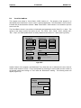
CARDIO Integrated Package
The Epson™ CARDIO™ integrates key PC components in a credit card-sized package.
diagram is shown in Figure 2.1, below:
Intel Processor
82360SL
SERIAL 1
SERIAL 2
PARALLEL
Main Memory
Keyboard I/F
81C51SL
BIOS ROM
(FLASH ROM)
KEYBOARD
MOUSE
Video Memory
VGA
CL-GD6412
CRT
IDE HDD
ISA BUS
Figure 2.1 - CARDIO™ Block Diagram
The block
PAGE 14
CH. 2
30 JUN 2000
MAN0051-01
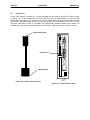
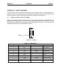
The CARDIO™ resides on the PC CPU main circuit board in a 236-pin socket. Because the CARDIO™
is socketed, the unit can be easily upgraded. Figure 2.2 shows an illustration of the CARDIO™.
Figure 2.2 - Epson™ CARDIO™
2.2
Hard Drive/Flash Drive
There are several Hard Drive/Flash Drive options for the PC CPU. The Hard Drive/Flash Drive is
mounted on the PC CPU's secondary board. The Hard Drive is preconfigured at our factory as drive C:
with the Operating System (Windows 95™ or NT™ and MS-DOS™ 6.22 by default) installed.
2.3
PCMCIA Socket
The PC CPU's secondary board includes a PCMCIA socket. "PCMCIA" stands for "Personal Computer
Memory Card International Association". This is an organization which establishes standards for
compact, credit card-sized memory cards for personal computers. The standards established by this
organization have been adopted by several different peripherals and memory cards (Ex: Modems and
Ethernet cards). PCMCIA established four different sizes of sockets; Type I, Type II, Type III, and Type
IV. These socket types vary by the width of cards which they will accept. The PC CPU PCMCIA socket
is Type II, which supports Type I and Type II cards.
MAN0051-01
30 JUN 2000
PAGE 15
CH. 2
Figure 2.3 - Example PCMCIA Type II Peripheral
PCMCIA cards are typically provided with software drivers from the manufacturer. These should allow
the peripheral to operate with most computers. However, because PCMCIA is a fairly new standard,
compatibility problems can exist from card-to-card and computer-to-computer. Horner APG is testing a
variety of PCMCIA peripherals. Contact Horner APG's Technical Support Department for a list of tested
PCMCIA cards.
2.3.1
Installing the PC Card
Horner APG has successfully tested and installed a 3Com™ Etherlink™ III PCMCIA. See Appendix D,
"Steps Taken for PC Card Installation", for documented procedures on installing a 3Com™ Etherlink™ III
PCMCIA.
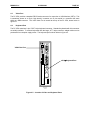
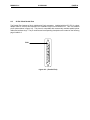
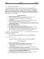
The physical installation of the PC Card is simple. The socket is located on the PC CPU's secondary
board at the bottom left (if looking at the PC CPU from the front). The PCMCIA socket is shown in figure
2.4. The "top" of the PC Card should face toward the power supply. When properly inserted, the PC
Card should fit snugly in the PCMCIA socket.
PAGE 16
CH. 2
30 JUN 2000
MAN0051-01
Hard Disk Drive LED
5V
VGA Video Port
High Density Parallel Port
PS/2Keyboard Port
Type II PCMCIA Socket
RJ-45 Serial Port
-
+
External Power Connector
PC C PU
Figure 2.4 - Front Panel Layout.
2.4
I/O Connections
2.4.1
Printer Port
The Parallel Port features a 26-pin high density D-sub connector. Included with the PC CPU is a short
adapter cable to convert this connector into a standard 25-pin D-sub Parallel Port. This is a standard
pinout (shown in Appx-A), compatible with commercially available parallel printer cables and software
keys.
2.4.2
COM Port Connections
The PC CPU supports two serial ports. COM1 is an RS-232 port with a RJ-45 connector. The pinout
(shown in Appx-A) is compatible with an adapter cable (included), which will convert it to a standard
personal computer 9-pin serial port. COM2 is the RS-422 port (with a DB15 female connector) on the
PLC power supply. The pinout is the standard SNP pinout (shown in Appx-A).
MAN0051-01
2.4.3
30 JUN 2000
PAGE 17
CH. 2
VGA Port
The PC CPU provides a standard DE15 female connector for connection to VGA Monitors (CRTs). This
is sometimes known as a 15-pin "high density" connector; as 15 pins reside in a connector the same
width as a DB9 connector.
2.4.4
Keyboard Port
The PC CPU contains a 6-pin, PS/2™-style keyboard connector. Standard keyboards with this connector
are widely available. To connect keyboards with the larger, AT™-style connector, adapter cables can be
purchased from computer supply stores.
2.4.5
External 3.5" Floppy Diskette/CD ROM Option
For those customers ordering the external floppy diskette or CD option, a parallel port interface to the
external drive is included. This drive is accessible from DOS as Drive D.
2.4.6
Frame Ground Connection
The Horner APG PC CPU has been carefully designed to withstand harsh industrial environments. The
key to the success of this design is a solid ground connection made to the external power connector on
the front of the module. A three-position terminal strip is present on the module for this purpose. A 12gauge conductor should be connected between this terminal strip and the earth ground on the control
panel. Without a proper Earth Ground, the noise immunity of the PC CPU is significantly reduced.
PAGE 18
CH. 2
2.4.7
30 JUN 2000
MAN0051-01
External Power Connector
Due to the significant power consumption of the PC CPU (up to 2A @ 5VDC), the module has been
designed to accept external power. A three-position terminal strip is located on the bottom of the module
and may be used to connect an external 5VDC power supply. Note: For optimum performance,
Horner APG recommends using an external power supply (rated at 3A or more @ 5VDC, low
ripple) with the PC CPU. The module overlay is labeled to indicate the proper polarity of the connection.
Before external power can be provided at these terminals, a jumper must be removed within the PC CPU
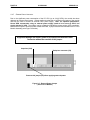
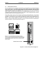
Module Assembly (note Figure 2.5 below).
Equipment damage will result if power is provided to the External Power
Connector without the removal of this jumper.
Capacitor (C28)
Backplane connector (P8)
Remove this jumper (J2) before applying external power.
Figure 2.5 - External Power Jumper
( Rear View of Module )
MAN0051-01
30 JUN 2000
PAGE 19
CH. 3
CHAPTER 3: BACKPLANE COMMUNICATIONS
The PC CPU utilizes the standard Series 90-30 backplane. This chapter is a description of the
capabilities of the PC CPU on this backplane.
3.1
Backplane Description
The PC CPU is intended to replace a CPU331-style CPU. Therefore, it resides in a Series 90-30 PLC
Model 331, 340, 341, 351, or 352 CPU baseplate. The baseplates are available in two versions, a 5-slot
(IC693CHS397), which is shown below in figure 3-1, and a 10-slot (IC693CHS391). This allows for either
5 slots or 10 slots for modules plus a slot for the power supply. The power supply must be installed in the
leftmost slot on the baseplate. The Model 331/340/341/351/352 CPU baseplate must always contain the
PC CPU module, which is installed in the slot labeled CPU/1 adjacent to the power supply.
The remaining four or nine slots in the CPU baseplate are available for analog I/O, discrete I/O, option
modules, and specialized option modules. A 25-pin D-type female connector is located at the far right of
the baseplate for connection to an expansion baseplate, if required. If additional system capacity is
required beyond the CPU baseplate, up to eight expansion baseplates can be connected through
available I/O expansion cables (or your custom made cables) in a chain to form an expansion system.
Figure 3.1 - Model 331/340/341/351/352 CPU 5-Slot Baseplate
PAGE 20
CH. 3
3.2
30 JUN 2000
MAN0051-01
IOCM
The PC CPU utilizes a GE Fanuc IOCM-Master chip. This silicon chip acts as a bridge between the PC
CPU and the Series 90-30 backplane. This is the same type of chip that is in other CPU modules (like
the CPU331).
3.3
Software Interface
The PC CPU communicates to the Series 90-30 backplane by means of the GE Fanuc IOCM chip and a
PIF (personal interface card). Unlike an entire card, the GE Fanuc IC693PIF300 (PC interface board
model) for instance, the PC CPU has a PIF "built into" the unit. This hardware allows the PC CPU to
communicate to the Series 90-30 backplane, therefore providing communication with other available
modules. In the interests of customer convenience, Horner APG has included a Visual Basic™ Demo, a
Visual C++™ Demo, 32-Bit DLL libraries, and DOS libraries (demo included) with the PC CPU package.
Documentation on these programs and libraries is located at the back of this manual in Appendix B.
By utilizing the PIF hardware, DLL libraries, and programs such as Visual Basic™ and Visual C++™, you
will be able to use or write programs that will provide interfacing and communication to other modules
connected to the backplane (or expansion rack(s)). By using these tools, attaining important information
from modules and running practical applications will be possible.
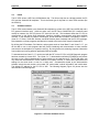
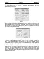
To demonstrate how Visual C++™ can be used with the PIF on the PC CPU, a 32-Bit Diagnostic program
has been created by Horner APG. The Visual C++™ demonstration software (PIF300Demo.exe) allows
the user to view various characteristics of each module on an expansion rack. The PIF300 demo can
only detect the characteristics of certain modules, one module at a time. It cannot detect parameters and
settings for the whole chain or even for a whole rack. Characteristics tested by the demonstration
software include the rack number, slot number, PIF card number, module information, and module data.
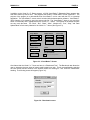
The default PIF address for the PC CPU is 300. The following diagram (Figure 3.2) shows how the
demonstration software appears.
Figure 3.2 - PIF Demo Software Screen
MAN0051-01
30 JUN 2000
PAGE 21
CH. 3
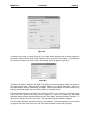
In addition to the Visual C++™ Demo program, a 32-Bit Visual Basic™ Diagnostic Demo program has
also been written by Horner APG. This program was written in Visual Basic™ 32-Bit Version 4.0. The
purpose of the program is to demonstrate how Visual Basic™ can be used with the PIF in a practical
application. The Visual Basic™ source code is included with the demonstration software. Visual Basic™
32-Bit Version 4.0 is needed to open the source code file. The Visual Basic™ demo is very much the
same in functionality and in appearance as the Visual C++™ demo. The options on the startup screens
are very much the same. The “Rack”, “Slot”, “Read”, “Write”, “Module Info”, “Run”, “Stop”, and “Data
Update Mode” all are nearly identical to the Visual C++™ demo (See Figure 3.3).
Select Module
Module Access
PLC Control
Rack
0
Read
Run
Slot
1
Write
Stop
Module Info
Exit
PIF Address
Set Port
Module Value
Status
Rack Status Rack Not Found
0
Benchmark
Test
Data Update Mode
Auto Read Update
Figure 3.3 - Visual Basic™ Screen
One feature that the Visual C++™ does not have is a "Benchmark Test." The Benchmark test allows the
user to determine the scan times of certain cards located on a rack. This is accomplished by selecting
the rack number and slot number of the desired module and clicking on “Test” under the “Benchmark”
heading. The following screen will appear (Figure 3.4).
Figure 3.4 - Benchmark screen
PAGE 22
CH. 3
3.4
30 JUN 2000
MAN0051-01
Software Locations
The files for the Visual Basic™ Demo, Visual C++™ Demo, 32-Bit DLL libraries, and DOS libraries (with
demo included), are located on the Hard Drive (drive C). These files are located (from Windows Desktop)
at My Computer/C:\Pif Software.
Periodic updates for these files will be available from the World Wide Web or from the Horner APG Web
site. The address for the Horner APG site is http://www.heapg.com.
MAN0051-01
30 JUN 2000
PAGE 23
CH. 4
CHAPTER 4: INSTALLATION AND WIRING
The installation and wiring of the Horner APG PC CPU was intended to be just as easy to wire as a
typical personal computer system. Like a typical PC, the PC CPU has a Serial Port, Parallel Port, Video
Port and Keyboard Port. In addition to these ports and the PCMCIA Socket (described in Chapter 2), the
PC CPU contains an External Power Connector. The location and instructions on connecting these
devices are described in this chapter.
Horner APG requires that the cables used with the PC CPU (Video, Parallel, Serial, Network from
PC Card, Keyboard and Power Supply) be 3 meters or less in length in order to promote maximum
performance of the PC CPU.
4.1
Serial Port
The PC CPU supports two serial ports. COM1 is an RS-232 port with a RJ-45 connector. This port is
located near the bottom of the PC CPU, shown below in figure 4.1. Horner APG provides a RS232 Cable
Converter (Part #HEC 500A0004) with the PC CPU package that plugs into this port. This Cable
Converter provides the user with RS232 communication (example use: serial mouse). This item is shown
in figure 4.2 below. COM2 is the RS-485 port (with a DB15 female connector) on the PLC power supply.
5V
RS232 end
RJ-45 Serial Port (COM1)
RJ-45 end
-
+
PC C PU
Figure 4.2 – RS232 Cable Converter
Figure 4.1 – Location of RJ-45 Serial Port
PAGE 24
CH. 4
4.2
30 JUN 2000
MAN0051-01
Parallel Port
The PC CPU contains 1 Parallel Port. This port is located near the center of the PC CPU, shown in figure
4.3 below. Due to the compactness of the PC CPU, this port is a “high density” 3-row 26-pin D-sub
Parallel Port. As a result of the uniqueness of this port, Horner APG includes a Printer Cable Converter
(Part #HEC 500A0003) which converts this pin configuration into the standard 2-row 25-pin D-sub
connector configuration, which is compatible with commercially available parallel printer cables and
software keys. This part is included with the PC CPU package. This item is shown in figure 4.4 below.
5V
High Density Side
Parallel Port
Standard Side
-
+
PC C PU
Figure 4.4 – Printer Cable Converter
Figure 4.3 – Parallel Port Location
MAN0051-01
4.3
30 JUN 2000
PAGE 25
CH. 4
Video Port
The PC CPU provides a standard DE15 female connector for connection to VGA Monitors (CRTs). This
is sometimes known as a 15-pin “high density” connector; as 15 pins reside in a connector the same
width as a DB9 connector. This VGA Video Port is located at the top of the PC CPU, shown below in
figure 4.5.
4.4
Keyboard Port
The PC CPU contains a 6-pin, PS/2™-style keyboard connector. Standard keyboards with this connector
are widely available. To connect keyboards with the larger, AT™-style connector, adapter cables can be
purchased from computer supply stores. The keyboard port is shown below in figure 4.5.
5V
VGA Video Port
PS/2 Keyboard Port
-
+
PC C PU
Figure 4.5 – Location of Video and Keyboard Ports
PAGE 26
CH. 4
4.5
30 JUN 2000
MAN0051-01
External Power Connector
Due to the significant power consumption of the PC CPU (up to 2A @ 5VDC), the unit has been designed
to accept external power. For optimum performance, Horner APG recommends using an external
power supply (rated at least 3A or greater @ 5VDC, low ripple) with the PC CPU, rather than
utilizing the power supply from the backplane. Before operating the PC CPU with an external power
supply, a jumper (J2) must be removed within the PC CPU Module assembly (see Figure 2.5). The use
of needle-nose pliers would aid in the removal of this jumper. After this jumper has been removed,
securely mount the unit to the PLC backplane (into Slot 1).
5V
The PC CPU contains a green male, 3-Pin Phoenix connector for external 5VDC power. This connector
is located at the bottom of the unit. The module overlay is labeled to indicate the proper polarity of the
connection. The top-most pin is Earth Ground, the middle pin is Positive, and the bottom-most pin is
Negative. Figure 4.6 shows a diagram of the location of the External Power Supply Input. Horner APG
Provides a 3-terminal female Phoenix (Part #PHO 17 54 46 5) connector with the PC CPU package for
customer convenience. This part is shown below in figure 4.7.
Figure 4.7 - 3-terminal Phoenix Connector showing
views of female connection (top left), 3D view (top right),
screw terminals (bottom left), and wire insertion points
(bottom right).
External Power Connector
-
+
PC C PU
Figure 4.6 – Location of External Power Supply Port
MAN0051-01
30 JUN 2000
PAGE 27
APPENDIX A
APPENDIX A: PINOUT DIAGRAMS
In order to provide as much information as possible on the ports of the PC CPU, this chapter, Appendix A,
describes in detail the pin configurations and descriptions of COM1 (RS-232 port), COM2 (RS-422 port)
and the Parallel Port. COM1 is described first, followed by COM2 and the Parallel Port.
A.1
RS-232 Port w/RJ-45 Connector (COM1)
COM1 is an RS-232 Port with a RJ-45 connector. The pinout (shown below) is compatible with an
adapter cable (included), which will convert it to a standard personal computer 9-pin serial port. The pin
configuration for the RS-232 side of the adapter cable is shown below in figure A.1. The pin numbers and
corresponding descriptions are located below in table A.1.
PIN 1
Figure A.1 – (COM1)
Table A.1 – COM1 Pinout
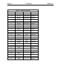
Pin Number
Signal Name
I/O
Description
1
N.C.
2
RXD
Input
Receive Data
3
TXD
Output
Transmit Data
4
-DTR
Output
Data terminal Ready
5
GND
6
-DSR
Input
7
-RTS
Output
8
-CTS
Input
9
N.C.
No Connection
Ground
Data Set Ready
Request To Send
Clear To Send
No Connection
PAGE 28
APPENDIX A
A.2
30 JUN 2000
MAN0051-01
PLC Serial Port (COM2)
The Series 90-30 PLC serial port is compatible with RS-422. An RS-232 to RS-422 converter is required
to interface to systems that provide RS-232 compatible interfaces. This part is available from Horner
APG (Part #HE693SNP232A). The Series 90-30 PLC, RS-422 serial port provides the physical
connection for SNP communication. This port is a 15-pin D-type female connector located on the Series
90-30 PLC Power Supply. Figure A.2 shows the serial port orientation and connector layout for the
Series 90-30 PLC types. Table A.2 shows the pin numbering and signal assignment applicable to the
PLC.
Figure A.2 – Series 90 PLC, RS-422 Serial Port Connector Configuration (COM2).
Table A.2 – COM2 Pinout
Pin Number
Signal Name
I/O
Description
1
Shield
2
N.C.
No Connection
3
N.C.
No Connection
4
N.C.
No Connection
5
+5V *
Output
+5V Power for HHP and RS-232/485 Converter
6
-RTS
Output
Request To Send
7
GND
8
CTS
9
RT *
10
-RXD
Input
Receive Data
11
RXD
Input
Receive Data
12
-TXD
Output
Ground
Input
Clear To Send
Terminating Resistor for RXD **
Send Data
13
TXD
Output
Send Data
14
RTS
Output
Request To Send
15
-CTS
Input
Clear To Send
* Signals available at the Connector (RS-422) on the Series 90-30 PLC but not included in the RS-422
specification.
** Termination resistance for the Receive Data (RXD) signal needs to be connected only on units at the
end of the lines. This is accomplished by connecting a jumper between pins 9 and 10 inside the 15-pin
D-shell.
MAN0051-01
A.3
30 JUN 2000
PAGE 29
APPENDIX A
25-Pin D-Sub Parallel Port
The Parallel Port features a 26-pin high-density D-sub connector. Included with the PC CPU is a short
adapter cable to convert this connector into a standard 25-pin D-sub Parallel Port. This is a standard
pinout (shown below in figure A.3). This pinout is compatible with commercially available parallel printer
cables and software keys. The pin numbers and corresponding descriptions are located on the following
page in table A.3.
PIN 1
Figure A.3 – (Parallel Port)
PAGE 30
APPENDIX A
30 JUN 2000
Table A.3 – Parallel Port Pinout
Pin Number
Signal Name
I/O
Description
1
LPTSTROBE
Bi-directional
Strobe
2
BLPTD0
Bi-directional
Data Bit 0
3
BLPTD1
Bi-directional
Data Bit 1
4
BLPTD2
Bi-directional
Data Bit 2
5
BLPTD3
Bi-directional
Data Bit 3
6
BLPTD4
Bi-directional
Data Bit 4
7
BLPTD5
Bi-directional
Data Bit 5
8
BLPTD6
Bi-directional
Data Bit 6
9
BLPTD7
Bi-directional
Data Bit 7
10
LPDACK
Input
Acknowledge
11
LPTBUSY
Input
Busy
12
LPTPE
Input
Paper End
13
LPTSLCT
Input
Select
14
LPDAFD
Output
Auto Feed
15
LPTERROR
Input
Error/Fault
16
LPTINIT
Output
Printer Init
17
LPTSLTCIN
Output
Select
18
GND
Ground
19
GND
Ground
20
GND
Ground
21
GND
Ground
22
GND
Ground
23
GND
Ground
24
GND
Ground
25
GND
Ground
MAN0051-01
MAN0051-01
30 JUN 2000
PAGE 31
APPENDIX B
APPENDIX B: PIF DOCUMENTATION
Included on every PC CPU Hard Drive are two demonstration programs (written in Visual C++ Version
4.2 and Visual Basic 32-Bit Version 4.0), 32-bit DLL libraries and DOS libraries. These programs are
available to the customer as examples of programs that may be written to interface with modules on the
Series 90-30 backplanes. Descriptions of these programs are included in this chapter for the customer to
examine. Also included are instructions for installing the PIF300 32-Bit DLL.
In order for the customer to create their own programs, several steps will be necessary. To begin with, a
programming package, such as Visual C++ or Visual Basic, will be necessary. We recommend
installing these on a different computer system other than the PC CPU (due to the large memory
requirements of some programs). After obtaining a programming package, the installation of 32- Bit DLL
libraries or DOS libraries onto this system will be required (Horner APG provides these libraries on a
floppy disk, which is included with the PC CPU package). This is required in order to link your program to
the libraries.
After you have all of the necessary software and files on your separate computing system, it will be
possible to create PIF 90-30 interface programs. When programming, you will use variables in the
libraries in order to manipulate the PIF or to assign procedures in your program. This process will enable
you to manipulate the MODULES on the Series 90-30 backplane. Once your executable program has
been written, you will need to transfer the compiled program to the PC CPU (using direct cable
connection, floppy, CD-ROM, or network connection). Horner APG has included the libraries on the Hard
Drive so you will not be required to transfer these. Finally, in order to run your Visual Basic program,
the PIF DLL, Visual Basic DLL and the Visual Basic executable files will be required. In order to run
your Visual C++ program, the PIF DLL and the Visual C++ executible files will be required.
B.1 Visual C++™ Demo
This program was written in Visual C++ Version 4.2. The purpose of the program is to demonstrate
how Visual C++ can be used in a practical application. The Visual C++ source code is included with
the demonstration software. Visual C++ Version 4.2 is needed to open the source code file.
The Visual C++ demonstration software (PIF300Demo.exe) allows the user to view various
characteristics of each module on an expansion rack. It is important to remember that the PIF300 can
only detect the characteristics of certain modules, one module at a time. It cannot detect parameters and
settings for the entire chain or rack. Characteristics tested by the demonstration software include the
following:
1.0.1. Rack number: Specifies what rack is being tested on the chain. Up to eight racks
on a chain can be tested. Rack 0 is reserved for the rack supporting the
HE693CPUxxx.
1.0.2. Slot number: Specifies what slot on a rack is being tested.
1.0.3 PIF card number: Specifies the PIF card being used. Up to four PIF cards can be
configured at a time (HE693CPUxxx contains 1, at address 300).
1.0.4 Module Information: Reads the type of module, type of rack, speed of rack, and
the number of %I’s, %Q’s, %AI’s, %AQ’s, %RI’s, and %RQ’s.
1.0.5 Module data: Reports to user what data is in the register of the specified module.
PAGE 32
APPENDIX B
30 JUN 2000
The following diagram (Figure B.1) shows how the demonstration software appears.
“buttons” will be explained below.
MAN0051-01
Each of the
Figure B.1
The diagnostic software allows the user to choose a module on a certain rack in a “chain” of expansion
racks. The module is selected by first choosing the PIF card that the rack or chain is connected to (with
address set at 300). This is accomplished by “clicking” on the “PIF300 Card” button, then selecting the
desired PIF card. The screen (Figure B.2) allows the user to configure up to four different PIF cards (only
one card may configured with the PC CPU).
Figure B.2
To configure the PIF card, select a card number 1 through 4 (in Figure B.2 card one is selected) and
choose the I/O Port Address (address 300) from the pull down menu. Next, choose the Watchdog
Timeout Setting (defaults to 1 second). After the PIF card is selected, select the rack with the attached
module. This is accomplished by placing the pointer over the “Rack” button and right clicking it on until
the preferred rack is selected. The same procedure is performed on the “Slot” button until the preferred
module is selected.
Module information is then viewed by placing the mouse pointer over the “Module Info.” Button and right
clicking it on. The “Selected Module Information” screen will appear (Figure B.3). The rack type should
specify whether a 5 slot or a 10 slot rack is being used. The rack speed will show what the baud rate of
the rack is. The “Module Type” will display the type of module located in the slot selected, as described in
the previous set of instructions.
MAN0051-01
30 JUN 2000
PAGE 33
APPENDIX B
Figure B.3
In reference to the “start up” screen (Figure B.1), the “Read” button allows the user to read the registers in
the selected module and the “Write” button allows the user to write data to the module. By selecting the
write function (clicking on the “Write” button), the following screen will appear (Figure B.4).
Figure B.4
The data to be written is entered in the “Data To Be Written” field and the register written to is entered in
the “Data Location” field. Data read from a module appears in the “Module Data field”. This can be
converted between Decimal, Hexadecimal, and Binary. Data can automatically be read and written to by
selecting “Auto Read Update” and “Auto Write Update” on the startup screen.
The demonstration software controls the “Run” function of the PLC. To put the PLC in Run mode, simply
click on the “Run” button on the start-up screen (Figure B.1). After run is selected, the “Run Mode
Heartbeat” status indicator should be flashing and the “Rack Status” field should indicate “Running”. To
stop the PLC, simply click on the “stop” button. The rack status field should indicate “Stopped”.
The “Run Mode Heartbeat” indicates the timing of the watchdog. This watchdog timing can be selected
by using the pull down menu found in the “PIF Card Select and Setup” screen (see Figure B.2).
PAGE 34
APPENDIX B
B.2
30 JUN 2000
MAN0051-01
Visual Basic Demo
This program was written in Visual Basic 32-Bit Version 4.0. The purpose of the program is to
demonstrate how Visual Basic can be used in a practical application. The Visual Basic source code is
included with the demonstration software. Note: Visual Basic 32-Bit Version 4.0 is needed to open the
source code file.
The Visual Basic demo is very similar in functionality and appearance as the Visual C++ demo. The
options on the startup screens are similar as well. The “Rack”, “Slot”, “Read”, “Write”, “Module Info”,
“Run”, “Stop”, and “Data Update Mode” are nearly identical to the Visual C++ demo (See Figure B.5).
Select Module
Module Access
PLC Control
Rack
0
Read
Run
Slot
1
Write
Stop
Module Info
Exit
PIF Address
Set Port
Module Value
Status
Rack Status Rack Not Found
0
Benchmark
Test
Data Update Mode
Auto Read Update
Figure B.5
Another feature of the program, the Benchmark Test, allows the user to determine the scan times of
certain cards located on a rack. This is accomplished by selecting the rack number and slot number of
the desired module and clicking on “Test” under the “Benchmark” heading. The following screen will
appear (Figure B.6).
Results
Scan Rate 1.253761E-04
Number of Scans 7976
Done
MAN0051-01
30 JUN 2000
PAGE 35
APPENDIX B
Figure B.6
The “Scan Rate” is measured in seconds. The “Number of Scans” is the actual number of scans
completed in one-second of scan time. This number will vary for different modules. The test is
implemented by writing a “1” to the buffer and then reading the “1” back in a loop for a complete second.
The “Number of Scans” and the “Scan Rate” will vary slightly depending on the system resources
(hardware, RAM, Processor). It will also vary slightly with the operating system (WindowsNT,
Windows95, network connections, etc…) of the PC.
PAGE 36
APPENDIX B
B.3
30 JUN 2000
MAN0051-01
Installing the PIF300 32-Bit DLL
The following instructions are for installing the PIF300 32-BIT DLL in both the Windows95 and
WindowsNT operating systems. Note: The instructions below have been written assuming that the
customer has a 3.5” floppy to their disposal. If you do not have a floppy drive, you must transfer the
program files by using a direct cable connection (Windows95 only) or by the use of a CD-ROM drive.
After the files have been transferred to a file folder or directory that you have created, the installation
program can be ran from this folder/directory. The instructions below can be followed assuming that the
actual floppy disks are not being utilized.
Windows95 Installation:
Insert Disk 1 in the 3.5” disk drive.
Left click on the Start button or simultaneously press the “Alt” key and the “S” key.
Left click on Run or simultaneously press the “Alt” key and the “R” key.
A window should appear with an “Open” data field. In the data field type
A:\Disk1\Setup
5. A “Welcome” window will appear; click “Next” or press “Enter” after reading the dialog.
6. At the “Read me Information” window, click “Next” or press “Enter”.
7. A “Choose destination Location” window will appear, choose a location, this location is here
the software will be downloaded, if the default settings are chosen, the software will be saved
under the following location.
C:\Program Files\PIF300 32-Bit DLL
8. After choosing the location press “Enter” or click on “Next”.
9. The “Start Copying File” window will appear. Press “Enter” or click on the “Next” button.
10. The software will now download from the floppy drive to the hard drive.
11. Approximately a quarter of the way through the download a window will appear asking for
disk 2. Remove disk 1 and insert disk 2. Press “Enter” or click on the “Next” button.
12. When the “Set Up Complete” window appears click on the “Finish” button.
1.
2.
3.
4.
The software is now installed and ready to be used. If all of the default selections were used, the
executable file can be found by selecting:
For the Visual C++ program:
My Computer\Program Files\PIF300 32-bit DLL\Visual C++ demo\PIF300Demo
For the Visual Basic Program:
My Computer\Program Files\PIF300 32-bit DLL\Visual Basic Demo\VBDemo
WindowsNT Installation:
1.
2.
3.
4.
Insert Disk 1 in the 3.5” disk drive.
Left click on the Start button or simultaneously press the “Alt” key and the “S” key.
Left click on Run or simultaneously press the “Alt” key and the “R” key.
A window should appear with an “Open” data field. In the data field type
A:\Disk1\Setup
5. A “Welcome” window will appear; click “Next” or press “Enter” after reading the dialog.
6. At the “Read me Information” window, click “Next” or press “Enter”.
7. A “Choose destination Location” window will appear, choose a location, this location is where
the software will be downloaded, if the default settings are chosen, the software will be saved
under the following location: C:\Program Files\PIF300 32-Bit DLL
8. After choosing the location press “Enter” or click on “Next”.
9. The “Start Copying File” window will appear. Press “Enter” or click on the “Next” button.
10. The software will now download from the floppy drive to the hard drive.
MAN0051-01
30 JUN 2000
PAGE 37
APPENDIX B
11. Approximately a quarter of the way through the download a window will appear asking for
disk 2. Remove disk 1 and insert disk 2. Press “Enter” or click on the “OK” button.
12. When the “Set Up Complete” window appears choose if computer is to be shut down now or
later and click on “Finish”. Note: In order to use the software, the computer must be
restarted.
13. At the next window, select “Finish”.
The software is now installed, and is ready to be used. If all of the default selections were used, the
executable file can be found by selecting:
For the Visual C++ program:
My Computer\32-bit PIF DLL for WINNT\Visual C++ demo\PIF300Demo
For the Visual Basic Program:
My Computer\32-bit PIF DLL for WINNT\Visual Basic demo\VBDemo
PAGE 38
APPENDIX B
30 JUN 2000
NOTES
MAN0051-01
MAN0051-01
30 JUN 2000
PAGE 39
APPENDIX C
APPENDIX C: DIRECT CABLE CONNECTION INSTRUCTIONS
Due to the compact design of the PC CPU, there are no internal 3.5” floppy or CD-ROM drives. In order
to download or upload data from the PC CPU, it is necessary to use an external 3.5” floppy drive or CDROM drive. An alternative to this method is to establish a direct cable connection between the PC
CPU and another computer. By using the direct cable connection method, it is possible to set up the PC
CPU as a host or guest computer. Once this is achieved, the transfer of data between the systems is
possible. Note: Windows™NT does not support a direct cable connection.
C.1
DIRECT CABLE CONNECTION INSTRUCTIONS
The direct cable connection between a host computer and the HE693CPUXXX is a simple and
straightforward procedure. This connection allows the transfer of data between two computers. This
eliminates the need for a floppy or CD-ROM drive. Follow the instructions below when transferring data
from a host computer to the HE693CPUXXX.
Connection
1) Locate the Parallel ports on both the host computer and the HE693CPUXXX.
2) Connect a 25-pin parallel cable between both ports.
Software Instructions
1) From Windows 95™ Desktop (on both of the computers), click Start.
2) Proceed to Programs/Accessories/Direct Cable Connection.
3) Click on Direct Cable Connection.
4) On the Direct Cable Connection Screen for the HE693CPUXXX, it should indicate “Guest computer
set up to connect to host using Parallel cable on LPT1.” If the screen does not indicate this,
proceed through the options and select guest for this computer, Parallel cable on LPT1, then click
Finish.
5) On the Direct Cable Connection Screen for the host computer, it should indicate “Host computer set
up to listen on Parallel cable on LPT1.”” If the screen does not indicate this, proceed through the
options and select host for this computer, Parallel cable on LPT1, then click Finish.
6) The next dialog box you should see on the guest computer (HE693CPUXXX) should indicate
“Status: Connecting via Parallel cable on LPT1…”
7) The next dialog box you should see on the host computer should indicate “Waiting for a guest
computer to connect via Parallel cable on LPT1.”
8) After a connection is made, the dialog box should indicate “Verifying user name and password.”
9) After this is completed, the guest computer is asked for the “Host computer name.” You can find the
name of your computer in My Computer/Control Panel/Network/Identification.
10) After these steps are completed, the examination and transfer of files from the host computer to the
guest computer may be initiated.
Note: If the connection between the host and the guest computer fails and you get an error message, try
limiting the name of your computer to one word.
PAGE 40
APPENDIX C
30 JUN 2000
NOTES
MAN0051-01
MAN0051-01
30 JUN 2000
PAGE 41
APPENDIX D
APPENDIX D: PC CARD INSTALLATION PROCEDURE
This chapter, Appendix D, describes in step-by-step format the procedure to install a 3Com Etherlink
III PCMCIA. This particular network card, a card that Horner APG has thoroughly tested, may be utilized
with the PC CPU in network communications.
D.1
PC Card Installation Procedure
This installation procedure was used to install a 3Com Etherlink III PCMCIA. To enable this PC Card
the following steps were taken;
1) From Windows95 Desktop, go to My Computer/Control Panel/System/Device Manager, Then
remove the PC Card Adapter from the screen.
2) next, go to My Computer/Control Panel/Add new hardware. Windows95 should be able to detect
the PC Card. Click finished
3) Next, the PC Card Wizard should appear. Choose NO for the questions, then click Finished.
4) Shut the computer down and restart, as indicated. When Windows95 restarts, a message should
appear that indicates that the new device was found. Click Finished.
5) Go to My Computer/Control Panel/System Properties/Device Manager. Next, manually select the
proper device to install (3Com Card in this case). Go to Other Devices/3Com Corporation-3C589D
Driver/Update Device Driver Wizard. Choose the option of manually selecting a driver from the list. I
choose Network Adapters/3Com/3Com Etherlink III PCMCIA (3C589/3C589B). Windows95
then proceeded to copy the necessary files from the Windows95 CD-ROM.
6) After these steps are completed, configure the Network settings to your specific protocols and restart
the computer. Windows95 should then successfully load and should prompt you for your network
password.
PAGE 42
APPENDIX D
30 JUN 2000
NOTES
MAN0051-01