1
A D D I T I O N A L I N F O R M AT I O N
CLV61x Dual Port (PROFINET IO)
Bar Code Scanner
Supplements to the operating instructions.
Integration into PROFINET IO.
Additional Information
CLV61x Dual Port (PROFINET IO)
This document describes the CLV61x Dual Port PROFINET bar code scanner (firmware version V1.31
or higher) in relation to its characteristics for PROFINET IO and GSDML configuration.
The required handling on the part of the PROFINET IO controller is described here using the example of
a PLC of the type Siemens S7 300 CPU with integrated PROFINET based on Step7 V5.5.
The bar code scanner CLV61x Dual Port PROFINET is referred to in this document as "CLV61x Dual Port"
or "CLV61x 2port".
Contents:
1
Functions of the CLV61x Dual Port .................................................................................................... 4
1.1
1.2
Range of functions of the CLV61x Dual Port .................................................................................. 4
Overview of the communication protocol of the CLV61x Dual Port. ................................................ 5
2
Electrical connection ........................................................................................................................... 6
3
Configuration of the CLV61x Dual Port: ............................................................................................. 6
3.1
3.2
3.3
3.4
4
Handling on the PLC side ................................................................................................................. 12
4.1
4.2
4.3
5
Configuration of the CLV61x Dual Port via GSDML configuration ................................................... 7
Configuration of the CLV61x Dual Port via USB with SOPAS ET ................................................... 8
Configuration of the CLV61x Dual Port via Ethernet (Port 2111/2112) with SOPAS ET ................ 10
Device replacement of the CLV61x Dual Port ............................................................................... 11
Installing the GSDML file .............................................................................................................. 12
Adding ID sensors in HW Config .................................................................................................. 13
Assigning PN names automatically............................................................................................... 14
Data channel of the CLV61x Dual Port ............................................................................................. 15
5.1
Handshake Mode / Confirmed Messaging .................................................................................... 15
5.1.1 Using the SICK function module for PROFINET IO .................................................................. 17
5.1.2 Byte layout CLV61x Dual Port .................................................................................................. 18
5.1.3 Receiving data.......................................................................................................................... 19
5.1.4 Example 1, receipt of a single block telegram (HS mode): ........................................................ 20
5.1.5 Example 2, receipt of a blocked telegram (HS mode): .............................................................. 21
5.1.6 Send data ................................................................................................................................. 22
5.1.7 Example 3, transmission of a single block telegram (HS mode) ............................................... 23
5.1.8 Example 4, transmission of a blocked telegram (HS mode): ..................................................... 25
5.1.9 Binary status bits In .................................................................................................................. 26
5.1.10 Binary Status Bits Out .............................................................................................................. 27
5.2
No-Handshake Mode.................................................................................................................... 27
5.2.1 Byte layout in No-Handshake Mode (NH): ................................................................................ 28
5.2.2 Receiving data in No-Handshake Mode ................................................................................... 28
5.2.3 Example 5, receive telegram (NH mode): ................................................................................. 29
5.2.4 Example 6, send telegram (NH mode) ...................................................................................... 30
6
Digital inputs/outputs ........................................................................................................................ 31
6.1
Ctrl bits ......................................................................................................................................... 31
6.1.1 Ctrl bits In ................................................................................................................................. 32
6.1.2 Ctrl bits Out .............................................................................................................................. 33
7
Appendix ............................................................................................................................................ 34
7.1
7.2
7.3
7.4
7.5
7.6
Quickstart CLV61x Dual Port – simple example with GSDML configuration ................................. 34
Quickstart CLV61x Dual Port – Example with configuration with SOPAS ET .............................. 38
Troubleshooting............................................................................................................................ 39
Resetting the CLV61x Dual Port to default setting ........................................................................ 40
Monitoring data output using the SOPAS ET terminal via USB ..................................................... 41
Monitoring data output using the SOPAS ET terminal via Ethernet............................................... 42
8017978 / 2014-11-20
© SICK AG · Germany · All rights reserved · Subject to change without notice
2
Additional Information
CLV61x Dual Port (PROFINET IO)
7.7
Function of the LEDs of the CLV61x Dual Port ............................................................................. 43
7.7.1 Status of the "SF" LED ............................................................................................................. 44
7.7.2 Status of the "BF" LED ............................................................................................................. 44
7.7.3 "P1 LNK/ACT" status LED ........................................................................................................ 44
7.7.4 "P2 LNK/ACT" status LED ........................................................................................................ 44
7.8
Firmware update of the CLV61x Dual Port via SOPAS ET ........................................................... 45
7.9
Software versions of the CLV61x Dual Port .................................................................................. 46
7.10 Tools for checking and assigning PN name and IP address from the PLC side ............................ 46
7.11 Checking and, if necessary, assigning a PROFINET name from the PLC side via HW Config ..... 48
7.12 Checking the PROFINET name using the PST (Primary Setup Tool) ........................................... 48
7.13 Searching the network using SOPAS Auto IP Scan ...................................................................... 49
7.14 Notes regarding operation on other PROFINET IO controllers ..................................................... 50
8017978 / 2014-11-20
© SICK AG · Germany · All rights reserved · Subject to change without notice
3
Additional Information
CLV61x Dual Port (PROFINET IO)
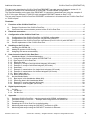
1 Functions of the CLV61x Dual Port
1.1
Range of functions of the CLV61x Dual Port
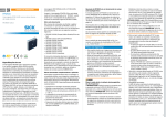
The CLV61x Dual Port has two Ethernet connections and can be used in both line and ring topology
(MRP Client). The 24 V supply is via connection cables with 4-pin M12 male connector.
24 V
24 V
PROFINET IO
The GSDML file of the CLV61x Dual Port must be used.
ID sensor
Model name / Version
GSDML file to be used
CLV61x Dual Port / from V1.31
GSDML-V2.3-SICK-CLV61x_2Port20141022.xml
Most up to date GSDML at:
http://www.sick.com/software
(or newer version)
Software type "GSD file".
Range of functions of the CLV61x Dual Port:
• Communication with the PROFINET/PLC (data channel for sending and receiving).
This can take place in CDF600 or CDF600 mode without a handshake.
The modes are compatible with CDF600/CMF400/ID sensors with PROFINET IO on Board.
• In CDF600 mode, the CLV61x Dual Port can be operated with the SICK function module for CLV6xx
(current version at: http://www.sick.com/software, category "Function module".)
• Ctrl bits for the PROFINET/PLC (according to the digital switching inputs and outputs)
• Configuration of the CLV61x Dual Port by the PLC possible via the GSCML file.
This makes device replacement easier.
• Configuration and monitoring of the CLV61x Dual Port with SOPAS ET:
- Via USB connection on the CLV61x Dual Port (Micro-USB)
- Via network via Port 2111/2112 (Ethernet TCP/IP connection), if the PC is connected directly to
the network.
The following types of triggering of the CLV61x Dual Port are possible:
a) Triggering by software trigger (configure CLV61x Dual Port by command).
b) Triggering by trigger bit in the Ctrl bits (configure CLV61x Dual Port by fieldbus input).
The CLV61x Dual Port can also be operated in free-running mode.
Quick start: See appendices to Chapters 7.1 and 7.2
8017978 / 2014-11-20
© SICK AG · Germany · All rights reserved · Subject to change without notice
4
Additional Information
CLV61x Dual Port (PROFINET IO)
The CLV61x Dual Port complies with PROFINET IO Conformance Class B.
The following features are supported:
•
•
•
•
•
•
•
1.2
Cyclic RT communication.
Automatic address issue for equipment replacement without engineering tool.
I&M 0 functionality as well as reading and writing from I&M 1-4
MediaReduncy support (MRP-Client)
FAST Ethernet 100 Base TX/FX
SNMP support
Neighborhood detection
Overview of the communication protocol of the CLV61x Dual Port
The CLV61x Dual Port provides two communication protocols. The communication protocol can be set
under "Parameter / Network Interfaces IOs / Profinet":
Operation of the SICK function blocks for PROFIBUS / PROFINET is only possible in Handshake mode /
Confirmed Messaging (CDF600).
CDF600 Handshake mode / Confirmed Messaging (default setting, recommended)
• Data channel compatible with the Byte Handshake Mode of the CDF600 PROFINET,
CDF600 PROFIBUS, CMF400 PROFIBUS, CDM425 and PROFINET on Board.
• Send and receive with max. telegram length of 4000 bytes (with blocking)
• A handshake is required on the PLC side.
• The SICK function blocks can be used for PROFIBUS / PROFINET
• Ctrl bits can be used to trigger or to set I/O's and to monitor.
CDF600 No Handshake mode:
• Data channel compatible with the No Handshake mode of the CDF600 PROFINET,
CDF600 PROFIBUS, CMF400 PROFIBUS, CDM425 and PROFINET on Board.
• The max. telegram length is limited by the size of the input/output range and is max. 123 bytes.
There is no fragmenting / blocking.
• No handshake is required on the PLC side.
• Ctrl bits can be used to trigger or to set I/O's and to monitor.
8017978 / 2014-11-20
© SICK AG · Germany · All rights reserved · Subject to change without notice
5
Additional Information
CLV61x Dual Port (PROFINET IO)
2 Electrical connection
See operating instructions for "CLV61x Dual Port (PROFINET IO) Bar Code Scanner" (Document 8017842)
Additional information available at http://www.mysick.com/en/clv61x_dual_port.
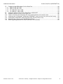
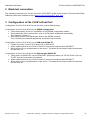
3 Configuration of the CLV61x Dual Port:
Configuration of the CLV61x Dual Port can be done in three different ways.
Configuration of the CLV61x Dual Port via GSDML configuration:
• Takes place directly in the PLC by addition of the GSDML configuration module.
• Allows automatic device replacement, even if the PN name is assigned automatically.
See Chapters 3.4 and 4.3.
• Only allows access to the parameters listed in the GSDML modules.
This is sufficient for standard applications and simple output formats.
Configuration of the CLV61x Dual Port via USB with SOPAS ET
• Carried out locally on the CLV61x Dual Port via SOPAS ET.
• When replacing devices, the CLV61x Dual Port must be reconfigured with SOPAS ET.
• Allows access only to all parameters of the device. This allows more complex output formats and
the like to be set.
Configuration of the CLV61x Dual Port via Ethernet with SOPAS ET
• Takes place via SOPAS ET over the PROFINET (Ethernet) network via TCP/IP (Port2111/2112).
The PC must be connected to the network.
• When replacing devices, the CLV61x Dual Port must be reconfigured with SOPAS ET.
• Allows access only to all parameters of the device. This allows more complex output formats and
the like to be set.
8017978 / 2014-11-20
© SICK AG · Germany · All rights reserved · Subject to change without notice
6
Additional Information
3.1
CLV61x Dual Port (PROFINET IO)
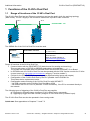
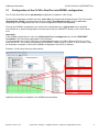
Configuration of the CLV61x Dual Port via GSDML configuration
The CLV61x Dual Port can be permanently configured by modules in HW Config.
For this, the configuration modules are to be added after the Ctrl bits and the data channel. First, the module
"Start Remote Config" must be selected and the module "End Remote Config" must be added last.
Depending on the configuration task, one or more configuration modules can be added.
Through this GSDML configuration, the scope of the configuration for a typical task can be handled.
Very extensive or special configurations must be carried out per SOPAS ET directly in the CLV61x Dual
Port.
Important!
If the GSDML configuration is used, the CLV61x Dual Port is configured every time the PROFINET
is restarted. This cannot be suppressed in the ID sensor.
If in the meantime the CLV61x Dual Port was deconfigured locally (via USB or Ethernet Port 2111/2112)
using SOPAS ET, the existing configuration at PROFINET restart is lost as a result. In such a case, it may
be necessary to change or remove the GSDML configuration in the PLC in advance.
Example: CLV61x Dual Port bar code scanner:
Additional information is available in the GSDML documentation.
8017978 / 2014-11-20
© SICK AG · Germany · All rights reserved · Subject to change without notice
7
Additional Information
3.2
CLV61x Dual Port (PROFINET IO)
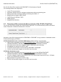
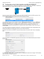
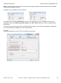
Configuration of the CLV61x Dual Port via USB with SOPAS ET
The CLV61x Dual Port can be configured via SOPAS ET V2.38 (or higher) with a USB cable. The Micro-B
USB female connector is located under the rubber cover of the CLV61x Dual Port.
USB Micro-B
Select the network wizard in SOPAS ET and connect USB. SOPAS ET shows the USB connection of the
CLV61x Dual Port and its serial number as the communications interface.
In the SOPAS ET Network Scan Assistant, search by USB must be activated. The required SDD file of
the CLV61x Dual Port must be installed on the PC under SOPAS ET. It can take a relatively long time
depending on the ID sensor if not installed and the SDD file has to be loaded from the device. It is
recommended to install the required SDD file in advance under "Device Catalog / Install" either online or
via the Internet.
If the USB connection is established, SOPAS ET 3.x launches automatically. When using SOPAS 2.38.3,
always start SOPAS ET manually and connect it to the CLV61x Dual Port.
With the CLV61x Dual Port, SOPAS ET shows the firmware status of the device under “Service / Operating”
data.
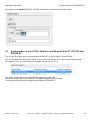
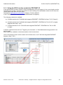
In the configuration, the PROFINET parameters are then shown on the "Network/Interfaces/IOs /Profinet"
device page.
The PROFINET station name (= PN Station Name) is displayed here and can be changed. The PN station
name can also be changed by the PLC.
8017978 / 2014-11-20
© SICK AG · Germany · All rights reserved · Subject to change without notice
8
Additional Information
CLV61x Dual Port (PROFINET IO)
See appendices to Chapters 7.10, 7.11, and 7.12.
This PN station name can also be used as a device name.
The device name is displayed in the parameter tree in SOPAS ET and helps when searching for devices.
If the CLV61x Dual Port is not yet active in the PROFINET data exchange to the IO Controller (PLC), the
PNIP Address, PN Subnet Mask and the PN Standard Gateway of the CDF61x Dual Port can also be set
here.
However, note that this is normally carried out automatically by the IO controller (PLC) if the PN station
name matches. If the IP is automatically assigned by the IO controller (PLC), the IP address is “temporarily”
accepted and then displayed as not remanent in SOPAS ET.
Remanent: (IP address)
This indicates whether the PN IP address, subnet and gateway are permanently stored and also
immediately available once power is restored or whether these have only been temporarily assigned and
the IP address is 0.0.0.0 following a restart. This characteristic is obligatory for PROFINET IO.
Remanent: (PN station name):
This indicates whether the station name has been permanently stored.
PN status:
connected Der CLV61x Dual Port is exchanging data with PROFINET.
This corresponds to the "BF" LED = off.
After changing the PN name and possibly the IP address, click "Apply" to use the new settings.
In addition, the Communications Mode can be set here. If changed from the default setting, the
parameters must be saved permanently and the CLV61x Dual Port restarted. For details about the
communications modes, see Chapter 5
Likewise, the IM data, such as Plant designation, Location designation, Installation date (mandatory format
yyyy-mm-dd hh:mm) and Additional information, can also be displayed and set here. This data is only
used for organization and can be read and written by the IO controller (PLC) or by the higher-level system.
The required output format must also be set. The output format given to PROFINET must not include any
STX/ETX frame, because transport works without this ID. If STX/ETX is set as the frame, the characters are
entered in the data for the PLC as control characters, which is not normally desirable.
8017978 / 2014-11-20
© SICK AG · Germany · All rights reserved · Subject to change without notice
9
Additional Information
CLV61x Dual Port (PROFINET IO)
Set output format without STX/ETX. This has already been removed in the default setting.
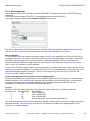
3.3
Configuration of the CLV61x Dual Port via Ethernet (Port 2111/2112) with
SOPAS ET
The CLV61x Dual Port can be configured with SOPAS ET V2.38 (or higher) via the network.
The CLV61x Dual Port must have a valid IP (IP is not 0.0.0.0) and the PC must be connected directly to
the network (TCP). The connection can be made via Port 2111 or 2112.
The actual configuration is then identical to the procedure with USB.
Note that normally, the PLC allocates the IP address assigned to the PN name.
This should avoid the need to change the IP address via SOPAS ET.
8017978 / 2014-11-20
© SICK AG · Germany · All rights reserved · Subject to change without notice
10
Additional Information
3.4
CLV61x Dual Port (PROFINET IO)
Device replacement of the CLV61x Dual Port
Under the following conditions, device replacement can be achieved with automatic configuration:
-
The components used (managed switches, etc.) allow automatic name allocation.
The topology was "taught" or configured.
Automatic allocation of PN names by PROFINET IO Controller (PLC) was activated. "Support
device replacement without exchangeable medium"
-
The IP address is automatically allocated by PROFINET IO Controller (PLC).
CLV61x Dual Port configuration was stored as GSDML configuration.
The new CLV61x Dual Port being used must be configured with Factory Default settings, or the PN
name at least must be empty.
If the new CLV61x Dual Port is then switched on in the PN, then the PLC recognizes that this station has
no PN name and automatically allocates the stored PN name. The IP address is then allocated to the PN
name accordingly. The configuration of the CLV61x Dual Port correspondingly takes place with the stored
GSDML configuration. The CLV61x Dual Port is thus completely configured without manual intervention.
See also Chapter 4.3 – Automatic allocation of PN name
Manual device replacement:
The CLV61x Dual Port can also be replaced manually and configured with SOPAS ET, either via the USB
interface or via the Ethernet TCP/IP interface Port 2111/2112.
GSDML configuration:
If a GSDML configuration is stored in the HW Config of the PROFINET IO Controller (PLC), then configuration
is always carried out automatically whenever the PROFINET IO is started. This overwrites the existing
parameters.
Any existing GSDML configuration therefore always overrides any parameters. This cannot be
suppressed locally in the CLV61x Dual Port.
8017978 / 2014-11-20
© SICK AG · Germany · All rights reserved · Subject to change without notice
11
Additional Information
CLV61x Dual Port (PROFINET IO)
4 Handling on the PLC side
4.1
Installing the GSDML file
The current GSDML files for the relevant sensors to be connected can be downloaded from the following
online product page:
www.sick.com/software, Select software type "GSD data file / GSDML".
Install the GSDML file associated with the CLV61x Dual Port to be connected as follows:
In the HW Config. Select "Options > Install GSD-Files...".
Then select "Options > Update Catalog".
The CLV61x Dual Port is then installed and displayed in the catalog as follows:
"PROFINET-IO / Additional Field Devices / Ident Systems / CLV61x, 2 port"
As shown in HW Config:
8017978 / 2014-11-20
© SICK AG · Germany · All rights reserved · Subject to change without notice
12
Additional Information
4.2
CLV61x Dual Port (PROFINET IO)
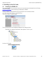
Adding ID sensors in HW Config
To add the ID sensors to be connected in the system, select the required device, e.g., "CLV61x 2port",
and drag-and-drop to the PROFINET line.
You can select the Device name for identifying the device in PROFINET by double clicking on the module.
If you activate "Assign IP address via IO controller", the PLC automatically assigns the IP address when
a device with the corresponding PROFINET device name has been found.
Make sure that no duplicate IP addresses are used. If two devices have the same IP address, change
one address before continuing. Use the SOPAS-ET Auto IP Scan, for example, to change the IP address of
the ID sensor, or change the IP address of the CLV61x Dual Port via the PLC HW Config.
8017978 / 2014-11-20
© SICK AG · Germany · All rights reserved · Subject to change without notice
13
Additional Information
4.3
CLV61x Dual Port (PROFINET IO)
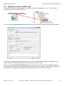
Assigning PN names automatically
The PN name can be automatically assigned by the PROFINET IO Controller (PLC), if:
a) This has been activated in the CPU (is activated by default):
Support device replacement without exchangeable medium = active
b) The topology has been taught-in. A PN partner is then firmly assigned to each used port.
c) The switches used must support this function, e.g., Scalance X200 series.
If a PN device is connected with an empty name and its type matches, the PN name stored on the
PROFINET IO Controller (PLC) is assigned. See also Chapter 3.4 – Device replacement.
8017978 / 2014-11-20
© SICK AG · Germany · All rights reserved · Subject to change without notice
14
Additional Information
CLV61x Dual Port (PROFINET IO)
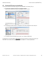
5 Data channel of the CLV61x Dual Port
Various communication protocols can be selected for the data channel in the CLV61x Dual Port.
These modes are specific to SICK and require appropriate handling on the software side.
The various communication protocols are described in the chapters below.
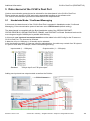
5.1
Handshake Mode / Confirmed Messaging
In this mode, the data channel of the CLV61x Dual Port is operated in Handshake mode / Confirmed
Messaging, if the communication protocol has been set to CDF600 mode (default setting).
The data channel is compatible with the Byte Handshake mode of the CDF600 PROFINET,
CDF600 PROFIBUS, CMF400 PROFIBUS, CDM425, and PROFINET on Board. Send and receive with
max. telegram length of 4000 bytes is possible with blocking.
In this mode, one input and one output module must be added in the HW Config for the ID sensor or
CLV61x Dual Port. The size can be selected.
A data size of up to 128 bytes (= 64 words) can be selected.
In the input/output modules, 5 bytes are used for administration. A module may contain from 32 bytes to
27 bytes of user data, for example, without necessitating blocking.
Input module (1 – 128 bytes)
Standard:
Output module (1 – 128 bytes)
"32 byte input" and "32 byte output"
Adding one input and one output module as well as the Ctrl bits:
8017978 / 2014-11-20
© SICK AG · Germany · All rights reserved · Subject to change without notice
15
Additional Information
CLV61x Dual Port (PROFINET IO)
Note: In the case of the CLV61x Dual Port, the input and output modules are added when the device is added.
These can be changed if required.
In addition, the I/O address must be selected.
The data must be handled consistently. Therefore, the I/O address for an S7-300/400 either must be
assigned so that it lies within its process image or the SFC 14/15 modules are used for consistent data
transmission.
The size of the process image can be viewed by double-clicking on the CPU in the hardware configuration
of S7. More details are available in the S7 documentation.
Example:
A process image size for the S7 CPU of 512 bytes is used here:
8017978 / 2014-11-20
© SICK AG · Germany · All rights reserved · Subject to change without notice
16
Additional Information
CLV61x Dual Port (PROFINET IO)
5.1.1 Using the SICK function module for PROFINET IO
If the optional SICK function module is used, the addresses of the I/O range incl. the correct length must be
assigned to the module. The block then takes over the handling of the Handshake mode and can thus also
receive data longer than the input range.
Download at http://www.sick.com/software, Category "Function Module".
If the Function Module is used, use of Handshake Mode is obligatory.
The following variants are available:
a) CLV6xx/Lector6xx for S7 300/400 with integrated PROFINET / PROFIBUS for Step 7 V5.5 ("Classic")
b) CLV6xx/Lector6xx for S7 300/400 with integrated PROFINET / PROFIBUS for TIA V12 SP1 or higher.
(Migrated from Step 7 V5.5)
c) CLV6xx/Lector6xx for S7 1200/1500 with integrated PROFINET / PROFIBUS for TIA V12 SP1
or higher.
If desired, optional actions such as "Triggering via command", or "Alter Matchcode during operation" can
also be used.
More details are available in the documentation of the function block.
Here is an example of the function module for CLV6xx/Lector on a S7 300 with integrated PROFINET
based on Step 7 V5.5:
8017978 / 2014-11-20
© SICK AG · Germany · All rights reserved · Subject to change without notice
17
Additional Information
CLV61x Dual Port (PROFINET IO)
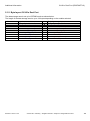
5.1.2 Byte layout CLV61x Dual Port
The data storage area is set up in CDF600 mode as shown below:
The length of the data storage area is up to 128 bytes depending on the module selected.
Address
1
2
3
4
5
6
7
…
n
Inputs (Data CLV PLC)
Binary status bits In
ReceiveCount (counter)
TransmitCountBack (counter)
ReceiveLength Lowbyte
ReceiveLength Highbyte
ReceiveData, Byte 1
ReceiveData, Byte 2
…
ReceiveData, Byte n - 5
8017978 / 2014-11-20
Output (Data PLC CLV)
Binary Status Bits Out
ReceiveCountBack (counter)
TransmitCount (counter)
TransmitLength Lowbyte
TransmitLength Highbyte
TransmitData, Byte 1
TransmitData, Byte 2
…
TransmitData, Byte n – 5
© SICK AG · Germany · All rights reserved · Subject to change without notice
18
Additional Information
CLV61x Dual Port (PROFINET IO)
5.1.3 Receiving data
Transmission from the CLV61x Dual Port to the PROFINET IO Controller requires no STX/ETX framing
characters.
If the output format contains STX/ETX, it is transmitted as data content to the PLC.
The output format must be formatted without STX/ETX in the sensor:
The CLV61x Dual Port puts the received data in the ReceiveData field and also adds the ReceiveLength.
The ReceiveCount value is also incremented to show that new data has been received.
Byte handshake:
To show that the PLC has received the data correctly, the PLC must respond to the CLV61x Dual Port by
copying the ReceiveCount value to the output side for ReceiveCountBack within 10 seconds. The second
input byte must be copied to the second output byte. (byte handshake ). If the CLV61x Dual Port
determines that both values are again identical, it can send the next data block. The ReceiveCount runs
from 1 to 255. 0 is omitted in normal operation.
If the CLV61x Dual Port sets the value to 0 during operation, it indicates that an error has occurred. In such
case, the count must be restarted. To restart the count, the PLC must respond with 0. Otherwise, the count
and data transmission does not continue. The PLC must always copy the ReceiveCount value to the
ReceiveCountBack without restriction.
Longer data telegrams are divided into blocks (fragmentation):
If the received data is too long and does not fit in the input range of the PLC completely, it is automatically
divided into blocks. The ReceiveLength always shows the length of the remaining data. In the first block,
the length corresponds to the complete telegram length. If the block was answered with the byte
handshake, the next block is sent and the length decremented.
Example:
Receipt of 100 bytes with a block size of 32-byte input (may contain up to 27 bytes in one block)
ReceiveCount ReceiveLength
ReceiveData
1
100
first 27 data bytes
2
73
next 27 data bytes
3
46
next 27 data bytes
4
19
last 19 data bytes, the rest will be filled with 00
The ReceiveLength must be checked to determine whether a single block or the start of longer fragmented
data was received. If ReceiveLength is longer than the data input variable, then fragmentation occurs.
If shorter, it is a single telegram.
8017978 / 2014-11-20
© SICK AG · Germany · All rights reserved · Subject to change without notice
19
Additional Information
CLV61x Dual Port (PROFINET IO)
5.1.4 Example 1, receipt of a single block telegram (HS mode):
Input: 16 bytes, output: 16 bytes, data telegram with up to 11 bytes single block
This can be done by triggering the CLV61x Dual Port, e.g. via the trigger git in the Ctrl bits.
Only data can then be received by the PLC.
Time:
1
2
3
4
Remarks:
Time 1:
The initial data block "CLV6xx-Data" (11 bytes) has been received and the PLC shows ReceiveCount = 1.
Time 2:
The PLC has detected the data and confirms it by copying from ReceiveCount to
ReceiveCountBack. The CLV61x Dual Port is now ready for the next data block.
Time 3:
The next data block "123456789" (9 bytes) has been received by the CLV61x Dual Port and the PLC
shows ReceiveCount = 2
Time 4:
The PLC has detected the data and confirms it by copying from ReceiveCount to
ReceiveCountBack. The CLV61x Dual Port is now ready for the next data block.
8017978 / 2014-11-20
© SICK AG · Germany · All rights reserved · Subject to change without notice
20
Additional Information
CLV61x Dual Port (PROFINET IO)
5.1.5 Example 2, receipt of a blocked telegram (HS mode):
Input: 16 bytes, output: 16 bytes, data telegram "CLV6xx-12345" with up to 12 bytes divided into 2 blocks
This can be done by triggering the CLV61x Dual Port, e.g. via the hardware. Only data can then be received by the PLC.
Time:
1
2/3
4
Remarks:
Time 1:
The first data block "CLV6xx-1234" (the first 11 bytes) has been received and the PLC shows
ReceiveCount = 1. The ReceiveLength is 12 bytes.
Time 2:
The PLC has detected the data and because it has noted that 12 bytes do not fit in the input range,
it knows that at least one more block follows. It confirms the first block by copying ReceiveCount to
ReceiveCountBack.
Time 3:
The CLV61x Dual Port sends the next block "5" (just 1 byte is left) to the PLC with ReceiveCount = 2 and
ReceiveLength = 1.
Time 4:
The PLC has detected the next block and confirms it by copying from ReceiveCount to
ReceiveCountBack. Transmission of the entire telegram has been completed.
The transportable data volume depends on the input range selected.
Input size minus 5 Input block size
The max. length of a data telegram is 4000 bytes divided into several blocks.
8017978 / 2014-11-20
© SICK AG · Germany · All rights reserved · Subject to change without notice
21
Additional Information
CLV61x Dual Port (PROFINET IO)
5.1.6 Send data
The PLC can also send data, such as commands, to the CLV61x Dual Port. This is optional and only
required if actions such as triggering by SOPAS ETcommand must be carried out. In the CLV61x Dual Port,
only commands that produce an echo or response, e.g., SOPAS ET commands, are permitted.
Data can be sent and received independently. It is recommended to first implement data receipt in the PLC
and then to start creating the send routine.
To send data, it must be copied to the output range of the CLV61x Dual Port. The send data is entered
without the STX/ETX frame.
Example:
PLC output range: 4 bytes with content: s R I 0
Sent as SOPAS command to ID sensor and answered with "sRA ...".
The Send begins by incrementing the TransmitCount-value by 1. The value must run from 1 to 255 and
then start again at 1. The 0 must be omitted.
By copying the TransmitCount to TransmitCountBack, the CLV61x Dual Port confirms that the data has been
sent. Before the next data block can be sent, the PLC must wait until these values are again identical.
If the CLV61x Dual Port has set the TransmitCountBack to 0, it indicates that an error has occurred and the
count must start again. The PLC also has to set the TransmitCount to 0 for approx. 1 second to confirm that
the error was detected. Data can then be sent again.
The cause of an error may be:
• Invalid length > 4000 bytes
• A transmission started with the first block, but subsequent blocks could not be sent or were faulty.
• TransmitCount was not incremented in the correct order.
The counting must be 1, 2, 3, … 255, 1, 2, 3, etc.
Longer send data must be divided into blocks (fragmentation):
If a longer data telegram needs to be sent, it can be transmitted to the CLV61x Dual Port in blocks.
Therefore, start with the first block and always set the length to the data length to be sent. If the block was
answered by the CLV61x Dual Port with TransmitCountBack as a byte handshake, the next block can be
sent and the length decremented. The next block must follow within 10 seconds. Otherwise, a timeout
occurs.
Example:
Transmission of 100 bytes with a block size of 32-byte output (may contain up to 27 bytes in one block)
TransmitCount
1
2
3
4
TransmitLength
100
73
46
19
8017978 / 2014-11-20
TransmitData
first 27 data bytes
next 27 data bytes
next 27 data bytes
last 19 data bytes
© SICK AG · Germany · All rights reserved · Subject to change without notice
22
Additional Information
CLV61x Dual Port (PROFINET IO)
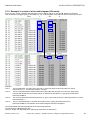
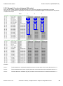
5.1.7 Example 3, transmission of a single block telegram (HS mode)
Input: 16 bytes, output: 16 bytes, data telegram with 4 bytes "sRI0" is sent.
The CLV61x Dual Port responds with "sRA ...".
The command can be used to query the software version of the sensor / SDD file or to generally check the
communication channel. This command can be used for all SOPAS ET based Cola-A sensors (CLV6xx, LECTOR62x,
RFH6xx, RFU6xx, etc.) irrespective of the configuration.
Time:
1/2
3/4
5
6/7
8
Remarks:
Time 1:
First data telegram "sRI0" (SDD version) was sent by setting TransmitCount = 1 on the output side. If the
CLV61x Dual Port has sent the data, it confirms it by copying TransmitCount to TransmitCountBack on the
input side.
Time 2:
The CLV61x Dual Port responds with "RA 0 6 CLV62x 5 V5.11" (22 bytes). The first 11 bytes ("sRA 0 6 CLV")
are reported to the PLC with ReceiveCount = 1 and ReceiveLength 22 bytes (total length).
The PLC has detected the data and because it has noted that 22 bytes does not fit in the input range,
it knows that another block follows. It confirms the first block by copying ReceiveCount to ReceiveCountBack.
Time 3:
The CLV61x Dual Port immediately sends the next (last) block "62x 5 V5.11" (11 bytes) to the PLC with
ReceiveCount = 2 and ReceiveLength = 11.
8017978 / 2014-11-20
© SICK AG · Germany · All rights reserved · Subject to change without notice
23
Additional Information
CLV61x Dual Port (PROFINET IO)
Time 4/5: The PLC has detected the additional data and confirms it by copying from ReceiveCount to
ReceiveCountBack. The CLV61x Dual Port is now ready for the next data block.
Time 6:
The next data telegram "sRIX" (here a faulty command) was sent by
incrementing TransmitCount on the output side to 2. The CLV61x Dual Port confirms this by
TransmitCountBack = 2 on the input side.
Time 7:
The device responds here with an error message "sFA 11" (6 bytes, FA = error response, 11 = character error).
This is reported to the PLC with ReceiveCount = 3 and ReceiveLength 6 bytes.
Time 8:
The PLC has detected the data and confirms it by copying the ReceiveCount to
ReceiveCountBack The device is now ready for additional data.
It is also advisable to test the required commands in advance e.g., using the SOPAS ET terminals connected to the
serial AUX interface or the AUX port of the Ethernet interface of the ID sensor. The CLV61x Dual Port can process
SOPAS ET commands from any of its data interfaces.
8017978 / 2014-11-20
© SICK AG · Germany · All rights reserved · Subject to change without notice
24
Additional Information
CLV61x Dual Port (PROFINET IO)
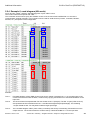
5.1.8 Example 4, transmission of a blocked telegram (HS mode):
Input: 16 bytes, output: 16 bytes, data telegram software trigger "sMN mTCgateon“ with 13 bytes.
Because the telegram is too long, 2 blocks are required.
This command can be used for all ID sensors (CLV6xx, Lector6xx, RFH6xx, RFU6xx, etc.) for triggering. The trigger
source must be configured to (SOPAS) command.
A successful reading with output is immediately shown. If desired, the command "sMN mTCgateoff" (14 bytes) can
also be used to terminate the trigger. This is not shown here.
Time:
1
2/3
4
5
6
7
Remarks:
Time 1:
The first data block of 11 bytes has been sent by setting TransmitCount = 1
with TransmitLength = 13.
If the CLV61x Dual Port has received the first data block, it confirms it by copying TransmitCount to
TransmitCountBack on the input side.
Time 2:
The second data block of the last 2 bytes has been sent by incrementing from
TransmitCount = 2 with TransmitLength = 2.
If the CLV61x Dual Port has received the second data block, it confirms it by copying TransmitCount to
TransmitCountBack on the input side.
Time 3:
The CLV61x Dual Port sends the echo of the trigger command "sMN mTCgateon" to the PLC with
ReceiveCount = 1 and ReceiveLength 15 bytes.
Time 4:
The PLC confirms receipt of the first 11 bytes with ReceiveCountBack = 1.
The CLV61x Dual Port then sends the remaining 2 bytes to the PLC with ReceiveCount = 2 and RecLength = 2.
Time 5:
The PLC confirms receipt of the data with ReceiveCountBack = 2
Time 6:
On receiving "Output immediately", the CLV61x Dual Port sends the result immediately, e.g., upon detection of
the bar code.
10 bytes ("1234567890") are reported to the PLC with ReceiveCount = 3 and ReceiveLength 10 bytes.
8017978 / 2014-11-20
© SICK AG · Germany · All rights reserved · Subject to change without notice
25
Additional Information
Time 7:
CLV61x Dual Port (PROFINET IO)
The PLC confirms receipt of the data with ReceiveCountBack = 3.
The TransmitCount must begin again with 1 when 255 is reached, i.e., 0 must be omitted.
The transportable data volume depends on the output range selected.
Output size minus 5 Output block size
The max. length of a data telegram is 4000 bytes divided into several blocks.
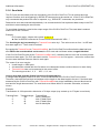
5.1.9 Binary status bits In
The first input byte (see chapter 5.1.2) displays the binary status bits In.
It contains some status bits and one heartbeat bit.
Bit
Name
Meaning
D7
D6
–
Transmit Buffer
Overrun
D5
Receive Buffer
Overrun
D4
D3
–
PLC Error
Reserved
0: No error
1: The CLV61x Dual Port has received send data from the PLC and the
queue is full.
Reset: With the next successful transmit telegram sent from the PLC.
0: No error
1: The receive buffer is full and the received data must be discarded.
Reset: With the next modified ReceiveCountBack from the PLC side.
Reserved
0: No error
1: The CLV61x Dual Port identified a handling error when sending data in
the PROFINET IO controller (PLC). The fieldbus module does not accept the
transmitted data if this error occurs and requires
resynchronization with the PROFINET IO controller (PLC). The PLC program
must be corrected based on the error.
Possible causes:
- Impermissible length (e.g., length > 4000).
- The subsequent block was not received within 10 seconds.
- TransmitCount was incremented in the wrong sequence.
If "PLC Error" bit is set, no send data are transmitted.
However, the receiver side is further processed.
If "PLC Error" bit is set, TransmitCountBack is set to 0.
The PLC Error bit is cleared
after TransmitCount is reset to 0 by the PLC.
D2
Heartbeat
0/1: Changes every second – shows the presence of the CLV61x Dual Port.
D1
–
Reserved
D0
–
Reserved
"Binary Status Bits" - Assignment in Handshake / No-Handshake mode
8017978 / 2014-11-20
© SICK AG · Germany · All rights reserved · Subject to change without notice
26
Additional Information
5.1.10
CLV61x Dual Port (PROFINET IO)
Binary Status Bits Out
The first output byte in the header is reserved. It must be set to zero.
Bit
Name
Meaning
D7
–
Reserved
D6
–
Reserved
D5
–
Reserved
D4
–
Reserved
D3
–
Reserved
D2
–
Reserved
D1
–
Reserved
D0
–
Reserved
"Binary Status Bits Out" - Assignment in Handshake / No-Handshake mode
5.2
No-Handshake Mode
The data channel of the CLV61x Dual Port is operated in No Handshake mode, if the communication
protocol has been configured with CDF600 NO Handshake mode.
The data channel is compatible with the No-Handshake mode of the CDF600 PROFINET, CDF600
PROFIBUS, CMF400 PROFIBUS, CDM425, and PROFINET on Board. The max. telegram length is limited
by the size of the input/output range and is max. 123 bytes. There is no fragmenting / blocking.
In this mode, one input and one output module, Ctrl bits In and Ctrl bits Out must be added in HW
Config for the CLV61x Dual Port. The size can be freely selected. In the input/output modules, 5 bytes are
used for administration. A module may contain from e.g. 32 bytes to 27 bytes of user data.
This mode is only recommended if the length of the received data does not exceed the input range minus 5.
It is also necessary to ensure that the PLC always has enough time to receive the data before the next data
block arrives. Therefore, this mode is only recommended for testing or for individual devices with low
communication load.
To select No-Handshake mode, "CDF600 No-Handshake mode" must be configured and permanently
saved in the ID sensor. The mode is only active after restarting the CLV61x Dual Port.
For the data channel, one input module and one output module must be selected as in CDF600 mode
(Handshake mode). In terms of the layout, the mode is identical to the HS mode except that fragmentation
is not possible on both the receiver and transmission sides.
The binary inputs and outputs are identical to the Handshake mode.
The Ctrl bits can also be used.
8017978 / 2014-11-20
© SICK AG · Germany · All rights reserved · Subject to change without notice
27
Additional Information
CLV61x Dual Port (PROFINET IO)
5.2.1 Byte layout in No-Handshake Mode (NH):
Address
1
2
3
4
5
6
7
…
N
Inputs (Data CLV PLC)
Binary inputs
ReceiveCount (counter)
TransmitCountBack (counter)
ReceiveLength Lowbyte
ReceiveLength Highbyte
ReceiveData, Byte 1
ReceiveData, Byte 2
…
ReceiveData, Byte n - 5
Output (Data PLC CLV)
Binary outputs
ReceiveCountBack (counter)
TransmitCount (counter)
TransmitLength Lowbyte
TransmitLength Highbyte
TransmitData, Byte 1
TransmitData, Byte 2
…
TransmitData, Byte n – 5
The length of the data storage area is up to max. 123 bytes depending on the module selected.
The first 5 bytes are used for administration and have special meaning. The remaining bytes from byte 6
onward are the ASCII data for sending / receiving.
The binary inputs and outputs are identical to the Handshake mode.
5.2.2 Receiving data in No-Handshake Mode
The data format is set as in Handshake mode without the STX/ETX frame.
The CLV61x Dual Port puts the received data in the ReceiveData field and also adds its ReceiveLength.
The ReceiveCount value is also incremented to show that new data has been received.
If the data is too long, the overhanging data is truncated and lost during transmission.
If additional data is received, it is always presented to the PLC directly. It is not checked if the user program
in the PLC has already received the data. As a result, data may be overwritten without warning. However,
the user program can check whether the ReceiveCount value is incremented by more than 1 to determine
that data has been overwritten.
8017978 / 2014-11-20
© SICK AG · Germany · All rights reserved · Subject to change without notice
28
Additional Information
CLV61x Dual Port (PROFINET IO)
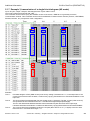
5.2.3 Example 5, receive telegram (NH mode):
Input: 16 bytes, output: 16 bytes, data telegram with up to 11 bytes are possible. No Handshake is required.
This can occur, for example, by triggering the CLV61x Dual Port via the fieldbus trigger bit, so that the PLC only has to
complete data receipt.
Time:
1
2
3
Remarks:
Time 1:
The first data block "12345678" (8 bytes) has been received and the PLC shows ReceiveCount = 1
Time 2:
The second data block "SICK" (4 bytes) has been received and the PLC shows ReceiveCount = 2.
Time 3:
The third data block "NoRead" (6 bytes) has been received and the PLC shows ReceiveCount = 3
8017978 / 2014-11-20
© SICK AG · Germany · All rights reserved · Subject to change without notice
29
Additional Information
CLV61x Dual Port (PROFINET IO)
5.2.4 Example 6, send telegram (NH mode)
Input: 16 bytes, output: 16 bytes, data telegram with 4 bytes "sRI0" is sent.
The CLV61x Dual Port responds with "sRA ...".
The command can be used to query the software version of the CLV61x Dual Port/SDD file or to check the
communication channel generally. This command can be used for all ID sensors (CLV6xx, Lector62x, RFH6xx,
RFU6xx, etc.) irrespective of the configuration.
Time:
1/2
3/4
Remarks:
Time 1:
First data telegram "sRI0" (SDD version) was sent by setting TransmitCount = 1 on the output side. If the
CLV61x Dual Port has sent the data, it confirms it by copying TransmitCount to TransmitCountBack on the
input side.
Time 2:
The CLV61x Dual Port responds with "RA 0 6 CLV62x 5 V5.11" (22 bytes). The first 11 bytes ("sRA 0 6 CLV")
are reported to the PLC with ReceiveCount = 1 and ReceiveLength 22 bytes (total length). The remaining
11 bytes of data are lost. You may want to select a larger input range.
Time 3:
The next data telegram "sRIX" (here a faulty command) was sent by incrementing TransmitCount on the
output side to 2. The CLV61x Dual Port confirms this by TransmitCountBack = 2 on the input side.
8017978 / 2014-11-20
© SICK AG · Germany · All rights reserved · Subject to change without notice
30
Additional Information
Time 4:
CLV61x Dual Port (PROFINET IO)
The CLV61x Dual Port responds here with an error message "sFA 11" (6 bytes, FA = error response,
11 = character error). This is reported to the PLC with ReceiveCount = 2 and ReceiveLength 6 bytes.
The TransmitCount must begin again with 1 when 255 is reached, i.e., 0 must be omitted.
Before sending again, TransmitCount and TransmitCountBack must be identical.
It is also advisable to test the required commands in advance, e.g., using the SOPAS ET terminals connected to the
USB AUX interface or the AUX port of the Ethernet interface of the ID sensor. The ID sensor can process SOPAS ET
commands from any of its data interfaces.
6 Digital inputs/outputs
The PLC can also read and control the information for the digital inputs/outputs of the CLV61x Dual Port.
6.1
Ctrl bits
The Ctrl bits can be added in the HW Config before or after the data channel.
8017978 / 2014-11-20
© SICK AG · Germany · All rights reserved · Subject to change without notice
31
Additional Information
CLV61x Dual Port (PROFINET IO)
6.1.1 Ctrl bits In
By adding the Ctrl bits In, the PLC can monitor the digital inputs and outputs of the CLV61x Dual Port.
Here is the assignment for the CLV61x Dual Port.
Add.
Bit
Name
Meaning
Add.+1
Add.+1
Add.+1
Add.+1
Add.+1
Add.+1
Add.+1
Add.+1
Add.
Add.
Add.
D0
D1
D2
D3
D4
D5
D6
D7
D8
D9
D10
Device Ready
–
Good Read *
No Read *
External Output 1
External output 2
Result 1
Result 2
Sensor 1
Add.
Add.
Add.
Add.
Add.
D11
D12
D13
D14
D15
–
–
–
Toggle
Status of the CLV61x Dual Port
Reserved
Status of the last read results *
Status of the last read results *
Only available as a bit logical, no hardware output
Only available as a bit logical, no hardware output
Only available as a bit logical, no hardware output
Only available as a bit logical, no hardware output
Reserved
Reserved
Status of dig. input sensor 1.
(Hardware dependent, equipment type on request)
Reserved
Reserved
Reserved
Reserved
Inverted after each read cycle.
Observe byte order: D0 stands for the least significant bit of Add.+1.
* The bits are valid if the "Toggle" bit changes.
8017978 / 2014-11-20
© SICK AG · Germany · All rights reserved · Subject to change without notice
32
Additional Information
CLV61x Dual Port (PROFINET IO)
6.1.2 Ctrl bits Out
By adding the Ctrl bits Out, various functions can be activated in the CLV61x Dual Port. For this to be
permitted, the respective function must be configured in the CLV61x Dual Port to "Fieldbus Input".
Assignment of the Ctrl bits Out for the CLV61x Dual Port.
Add.
Bit
Name
Meaning
Add.+1
D0
Trigger
Add.+1
Add.+1
D1
D2
Teach In 1
Add.+1
Add.+1
Add.+1
Add.+1
Add.+1
Add.
Add.
Add.
Add.
Add.
Add.
Add.
Add.
D3
D4
D5
D6
D7
D8
D9
D10
D11
D12
D13
D14
D15
–
–
–
–
–
–
–
Object trigger for the CLV61x Dual Port.
Object trigger must be configured for "Fieldbus input".
Reserved
The Teach In 1 teach-in process is triggered. Teach In 1 activation
must be configured for "Fieldbus input".
Reserved
Reserved
Reserved
Reserved
Reserved
Reserved
Reserved
Reserved
Reserved
Reserved
Reserved
Reserved
Reserved
Observe byte order: D0 stands for the least significant bit of Add.+1
Example:
Set CLV61x Dual Port to Object Trigger start via "Fieldbus input " and stop via "Trigger source".
The ID sensor can be triggered by the PLC using the bit D0 "Trigger":
8017978 / 2014-11-20
© SICK AG · Germany · All rights reserved · Subject to change without notice
33
Additional Information
CLV61x Dual Port (PROFINET IO)
7 Appendix
7.1
Quickstart CLV61x Dual Port – simple example with GSDML configuration
Quickstart describes the commissioning of the CLV61x Dual Port with GSDML configuration by the
PROFINET Controller (PLC) centrally. A simple example with No Handshake was chosen here, so that
no program or function module needs to be used for data transfer.
Provide 24 V DC supply for the CLV61x Dual Port and connect it with the PROFINET IO network.
S7 HW configuration:
•
•
Install the CLV61x GSDML file in the PLC (S7 HW Config).
HW Config: "Install Extras / GSD", also see Chapter 4.1.
The CLV61x Dual Port is then added as follows in the S7 HW catalog:
"PROFINET IO / Additional FIELD DEVICES / Ident Systems / CLV61x, 2port"
Drag the CLV61x Dual Port onto the PROFINET line.
Double click the CLV61x icon and allocate the PROFINET name.
This PN name is the individual identifier for the PN and must be clearly allocated for each relevant
device, e.g., "Scanner 10":
•
When adding the CLV61x Dual Port, these four modules are added automatically:
Both of the modules Ctrl Bits In and Ctrl Bits Out must be used.
Both data modules can also be exchanged for smaller or larger ones if required.
The I/O address can be customized.
8017978 / 2014-11-20
© SICK AG · Germany · All rights reserved · Subject to change without notice
34
Additional Information
CLV61x Dual Port (PROFINET IO)
GSDML configuration:
Note that GSDML configuration is optional and is sent to the CLV61x Dual Port every time PROFINET starts.
This overwrites the existing parameters in the CLV61x Dual Port.
Example:
•
GSDML configuration must always begin with "01_Start_Remote Config":
For this, only Code 128 was activated and triggering via fieldbus bit selected.
•
Secondly, reading configuration by the "11 Reading Config" module was selected:
For example, the scanning frequency can be adjusted here.
•
As this is a simple application, the Handshake mode is switched off.
Note:
No Handshake must be carried out on the PLC and simple operation with a short data string can
take place.
If the SICK function module is to be used, the Handshake must be switched on.
•
Additional configuration modules can be selected according to the application.
The process must always be completed with the "99_End_Remote Config" module.
•
The HW Config must finally be saved and transferred to the PLC.
8017978 / 2014-11-20
© SICK AG · Germany · All rights reserved · Subject to change without notice
35
Additional Information
CLV61x Dual Port (PROFINET IO)
PROFINET name allocation:
The PN name allocation ("baptism") can be carried out very simply following prior checking of the
PN name by allotting the PN name from the S7 HW Config.
•
First mark the Ethernet cable ( Cable is continuously identified)
•
Next, select the PN name test: "PLC / Ethernet / Verify Device Name".
•
It will now be verified whether the desired PN name is available in the network.
Then click "Assign Name".
•
In the following dialog box, the PN name to be allocated can be selected at the top, and at the
bottom the PN devices present in the network are represented.
Now the desired device can be selected and using "Assign name", the PN name is transferred to
this device.
If there is any uncertainty as to the location of each device, flashing can be activated for a PN
device beforehand. The CLV61x Dual Port signals flashing at the "SF" LED.
8017978 / 2014-11-20
© SICK AG · Germany · All rights reserved · Subject to change without notice
36
Additional Information
CLV61x Dual Port (PROFINET IO)
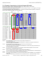
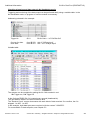
Checking triggering and data output in No Handshake mode:
Triggering and monitoring of the data output can be performed easily using a variable table. In the
No Handshake mode, no program or function module is necessary.
Addressing selected in the example:
Trigger bit:
Q1.0
Counter for data:
User data:
from IB 256: Adr of "32 Byte Input"
from IB 261: Adr + 5 of "32 Byte Input"
Bit 0 of Adr + 1 of "Ctrl Bits Out"
Variable table:
The scanner can be controlled by setting the A1.0 bits marked in red:
1 Trigger on, 0 Trigger off
In the first byte EB256, Bit 2 is inverted every second (heartbeat bit).
The user data is visible in the area outlined in blue.
The "Receive Count" counter increments with each block of data received. On overflow, the 0 is
skipped: 1 to 255, 1 to 255.
In the example, eight data bytes were received, with the content "12345678".
For more details on data reception, see Chapter 5.2.
8017978 / 2014-11-20
© SICK AG · Germany · All rights reserved · Subject to change without notice
37
Additional Information
7.2
CLV61x Dual Port (PROFINET IO)
Quickstart CLV61x Dual Port –
Example with configuration with SOPAS ET
Quickstart describes the commissioning of the CLV61x Dual Port without GSDML configuration.
If not already done, the CLV61x Dual Port must concurrently be configured with SOPAS ET.
The procedure for this is identical to that under 8.1, except that the GSDML configuration page is not
necessary.
The configuration includes only these four modules and no configuration modules:
The remaining sequence for commissioning is identical from here on.
Following the PROFINET IO commissioning, it is appropriate to configure the sensor using SOPAS ET.
The connection for this can be made via USB or Ethernet Port 2111 (or 2112).
If no Handshake is to be used, this can be set in SOPAS ET under:
"Network Interfaces/ IOs /Profinet":
If the function module is to be used, the Handshake mode must be switched on immediately. See also
Chapter 5.1.1.
8017978 / 2014-11-20
© SICK AG · Germany · All rights reserved · Subject to change without notice
38
Additional Information
7.3
CLV61x Dual Port (PROFINET IO)
Troubleshooting
This chapter provides some information on fault finding and rectification in the form of a condensed list.
•
Check the voltage supply – Is the upper sensor LED lit blue?
•
Check the Ethernet connection – Is LED P1 or LED P2 lit?
LED P1/P2: Green = connected, yellow = data exchange
•
Was the correct CLV61x Dual Port GSDML file used?
GSDML-V2.3-SICK-CLV61x_2Port-20141022.xml, or later.
•
Is the CLV61x Dual Port visible in the PROFINET with suitable name and IP?
Check the PN name via HW Config or the PST tool. See Chapters 7.10, 7.11, and 7.12
•
Read CLV61x Dual Port with SOPAS ET.
Check parameters such as PN name and IP address under "Network /Interfaces IOs / Profinet":
•
Is the mode selected suitable?
Handshake =
Function module or program necessary.
(Check E/A addresses and data length)
No Handshake =
Operation possible without programming
•
Is the triggering selected suitable?
Is the correct bit being used for fieldbus trigger? Bit 0 of Adr + 1 of "Ctrl Bits Out"
•
Can the CLV61x Dual Port read the desired code in Quickstart as a percentage value?
•
Check the GSCML configuration. If necessary, test by removing the GSDML configuration modules.
8017978 / 2014-11-20
© SICK AG · Germany · All rights reserved · Subject to change without notice
39
Additional Information
CLV61x Dual Port (PROFINET IO)
If no data arrives:
•
Check modules in HW Config.
•
Address for inputs and outputs correctly applied in calling up the functional component?
(Hex/dec representation)
•
If no block is used, is the I/O address within the process image?
Or get data with SFC 14/15.
•
Heartbeat bit appears?
•
Does only the first data block appear and no others?
Then the handshake does not work correctly? Check addresses.
Set handshake manually or with function block.
7.4
Resetting the CLV61x Dual Port to default setting
If the CLV61x Dual Port is connected to SOPAS ET, the device can be completely reset using the "Factory
Default" button:
Then carry out Permanent Storage via the "Green Diskette" symbol on the extreme right.
Following this, the PN name is empty and the CLV61x Dual Port can, if necessary, automatically get a new
name from the PLC.
8017978 / 2014-11-20
© SICK AG · Germany · All rights reserved · Subject to change without notice
40
Additional Information
7.5
CLV61x Dual Port (PROFINET IO)
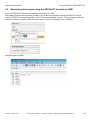
Monitoring data output using the SOPAS ET terminal via USB
Open the SOPAS ET terminal and establish a connection via USB.
Every data format can be monitored via USB. It should be noted, however, that the SOPAS ET terminal
requires STX/ETX framing and possibly a CR LF at the end to display correctly. The most simple method is
therefore to select a suitable output format as Output Format 2 and assign it to the USB port.
Monitoring data via USB:
8017978 / 2014-11-20
© SICK AG · Germany · All rights reserved · Subject to change without notice
41
Additional Information
7.6
CLV61x Dual Port (PROFINET IO)
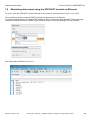
Monitoring data output using the SOPAS ET terminal via Ethernet
To do so, open the SOPAS ET terminal and set up a connection via Ethernet on Port 2111 (or 2112).
Only a data format that contains STX/ETX framing can be monitored via Ethernet.
For correct representation in the SOPAS ET terminal, a CR LF at the end is also advisable. The most simple
method is therefore to select a suitable output format as Output Format 2 and assign it to the USB port.
Monitoring data via Ethernet Port 2111:
8017978 / 2014-11-20
© SICK AG · Germany · All rights reserved · Subject to change without notice
42
Additional Information
7.7
CLV61x Dual Port (PROFINET IO)
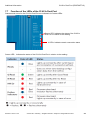
Function of the LEDs of the CLV61x Dual Port
Statuses and errors for the CLV61x Dual Port are indicated via 5 status LEDs:
Sensor LED: Indicates the status of the CLV61x
Dual Port in relation to the reading
4 LEDs: Indicate network connection status
Sensor LED: Indicates the status of the CLV61x Dual Port in relation to the reading:
8017978 / 2014-11-20
© SICK AG · Germany · All rights reserved · Subject to change without notice
43
Additional Information
CLV61x Dual Port (PROFINET IO)
The other four LEDs indicate the network connection status:
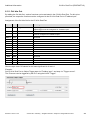
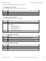
7.7.1 Status of the "SF" LED
The "SF" LED indicates the internal status of the CDF600-22xx.
SF LED
(red)
OFF
ON
Flashing
Meaning
CLV61x Dual Port without internal error
Activation of the PROFINET interface
"Flashing" was, for example, required by the HW configuration.
7.7.2 Status of the "BF" LED
The "BF" LED indicates the status of the PROFINET.
BF LED
(red)
OFF
ON
Meaning
Data exchange OK, CLV61x Dual Port operates OK as PROFINET slave
No connection to PROFINET IO controller (PLC). No data exchange.
Possible reasons:
•
Flashing
(0.5 Hz)
Bus not connected
•
Master not available / OFF
•
Incorrect PROFINET name
•
Wrong GSDML file used
•
Wrong GSDML module selected
•
Parameterization / configuration error in IO controller, no data exchange
7.7.3 "P1 LNK/ACT" status LED
P1 LNK/ACT Meaning
LED
OFF
ON (green)
CLV61x Dual Port is not connected to any active network; no data traffic
Active network connected
ON (orange) LED flickers when the CLV61x Dual Port is sending or receiving data, data traffic
7.7.4 "P2 LNK/ACT" status LED
P2 LNK/ACT Meaning
LED
CLV61x Dual Port is not connected to any active network; no data traffic.
OFF
ON (green) Active network connected
ON (orange) LED flickers when the CLV61x Dual Port is sending or receiving data, data traffic.
8017978 / 2014-11-20
© SICK AG · Germany · All rights reserved · Subject to change without notice
44
Additional Information
7.8
CLV61x Dual Port (PROFINET IO)
Firmware update of the CLV61x Dual Port via SOPAS ET
The CLV61x Dual Port be updated with SOPAS ET via USB or via TCP/IP (Port 2111 and 2112). If the
update is carried out via Ethernet, the IP address must be accessible in a stable condition, i.e., the CLV61x
Dual Port must retain this IP address even after a restart, or retrieve it from the attached PLC.
It may be necessary to test beforehand whether the CLV61x Dual Port is reachable after rebooting.
1. Use the SOPAS ET Network Scan Assistant to scan the network
The CLV61x Dual Port is found via USB
2. Add attached ID sensor to the project:
3. Log into the device using the password for user-level service: "servicelevel":
5. Use the command "CLV ... > Firmware Download" to open the download window:
6. Select the current firmware (.fwp file) in the download window and the matching *.key file:
7. Start download. Password for user-level service: "servicelevel":
8. Depending on the ID sensor, the download can take up to approx. 40 min. and the message "Download
succeeded" will appear once it is complete:
8017978 / 2014-11-20
© SICK AG · Germany · All rights reserved · Subject to change without notice
45
Additional Information
7.9
V1.31
CLV61x Dual Port (PROFINET IO)
Software versions of the CLV61x Dual Port
First firmware version of the CLV61x Dual Port
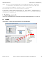
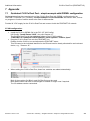
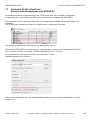
7.10 Tools for checking and assigning PN name and IP address from the
PLC side
You can use this tool in the S7 manager to search for a PROFINET device and to check or change the
PROFINET device name and IP address.
Or you can start it in the S7 HW Config:
8017978 / 2014-11-20
© SICK AG · Germany · All rights reserved · Subject to change without notice
46
Additional Information
CLV61x Dual Port (PROFINET IO)
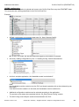
This window opens in both cases:
You can scan the network using "Start":
You can search for a device (MAC address) and assign this a device name or an IP address.
8017978 / 2014-11-20
© SICK AG · Germany · All rights reserved · Subject to change without notice
47
Additional Information
CLV61x Dual Port (PROFINET IO)
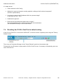
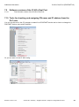
7.11 Checking and, if necessary, assigning a PROFINET name from the
PLC side via HW Config
You can use this tool to check the PROFINET names of the PROFINET devices.
Select the PROFINET line and start this function:
If some names are not available, a name can be assigned here.
7.12 Checking the PROFINET name using the PST (Primary Setup Tool)
Alternatively, you can use the PST tool from Siemens to scan the PROFINET devices in the network and
assign the IP addresses and device name.
8017978 / 2014-11-20
© SICK AG · Germany · All rights reserved · Subject to change without notice
48
Additional Information
CLV61x Dual Port (PROFINET IO)
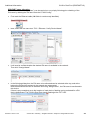
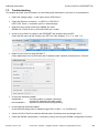
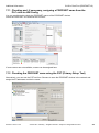
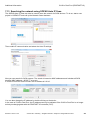
7.13 Searching the network using SOPAS Auto IP Scan
The SOPAS Auto IP Scan can also be used to scan the network for SICK devices. To do so, start a new
project in SOPAS ET and call up the Network Scan Assistant:
Then enable IP communication and select the Auto IP settings:
Now you can search for SICK sensors. The search is based on MAC addresses and includes all SICK
devices (MAC address = 00 06 77 xx xx xx).
A CLV61x Dual Port is also found if the IP address is 0.0.0.0.
You can also change the IP address by double-clicking on the device.
In the case of CLV61x Dual Port, the IP address can only be adjusted if the CLV61x Dual Port is no longer
actively exchanging data with the PROFINET IO controller (PLC).
8017978 / 2014-11-20
© SICK AG · Germany · All rights reserved · Subject to change without notice
49
Additional Information
CLV61x Dual Port (PROFINET IO)
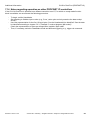
7.14 Notes regarding operation on other PROFINET IO controllers
If the CLV61x Dual Port is operated on a different controller to an S7, for which no ready-made function
block is available, we recommend the following procedure:
-
-
To begin, set No Handshake.
Set triggering to fieldbus input or slow (e.g., 5 sec.) auto cycle and only examine the data receipt
at first.
Use Hex representation for the first 10 input bytes: Can the Heartbeat bit be identified? Can the data
be identified according to chapter 5.2.3., Example 5, receive telegram (NH mode)?
Check the representation of bytes per integer/value variable. Byte order?
Then, if necessary, switch to Handshake mode and different triggering, e.g., trigger via command.
8017978 / 2014-11-20
© SICK AG · Germany · All rights reserved · Subject to change without notice
50
Additional Information
CLV61x Dual Port (PROFINET IO)
(Blank page)
8017978 / 2014-11-20
© SICK AG · Germany · All rights reserved · Subject to change without notice
51
8017978/2014-11-20 ∙ MT_8M/GK ∙ A4 4c int43
Australia
Phone+61 3 9457 0600
1800 33 48 02 – tollfree
E-Mail [email protected]
Belgium/Luxembourg
Phone +32 (0)2 466 55 66
E-Mail [email protected]
Brasil
Phone+55 11 3215-4900
E-Mail [email protected]
Canada
Phone+1 905 771 14 44
E-Mail [email protected]
Česká republika
Phone+420 2 57 91 18 50
E-Mail [email protected]
China
Phone +86 4000 121 000
E-Mail [email protected]
Phone +852-2153 6300
E-Mail [email protected]
Danmark
Phone+45 45 82 64 00
E-Mail [email protected]
Deutschland
Phone+49 211 5301-301
E-Mail [email protected]
España
Phone+34 93 480 31 00
E-Mail [email protected]
France
Phone+33 1 64 62 35 00
E-Mail [email protected]
Great Britain
Phone+44 (0)1727 831121
E-Mail [email protected]
India
Phone+91–22–4033 8333
E-Mail [email protected]
Israel
Phone+972-4-6881000
E-Mail [email protected]
Italia
Phone+39 02 27 43 41
E-Mail [email protected]
Japan
Phone+81 (0)3 5309 2112
E-Mail [email protected]
Magyarország
Phone+36 1 371 2680
E-Mail [email protected]
Nederland
Phone+31 (0)30 229 25 44
E-Mail [email protected]
SICK AG |Waldkirch|Germany|www.sick.com
Norge Phone+47 67 81 50 00
E-Mail [email protected]
Österreich
Phone+43 (0)22 36 62 28 8-0
E-Mail [email protected]
Polska
Phone+48 22 837 40 50
E-Mail [email protected]
România
Phone+40 356 171 120
E-Mail [email protected]
Russia
Phone+7-495-775-05-30
E-Mail [email protected]
Schweiz
Phone+41 41 619 29 39
E-Mail [email protected]
Singapore
Phone+65 6744 3732
E-Mail [email protected]
Slovenija
Phone+386 (0)1-47 69 990
E-Mail [email protected]
South Africa
Phone+27 11 472 3733
E-Mail [email protected]
South Korea
Phone+82 2 786 6321/4
E-Mail [email protected]
Suomi
Phone+358-9-25 15 800
E-Mail [email protected]
Sverige
Phone+46 10 110 10 00
E-Mail [email protected]
Taiwan
Phone+886 2 2375-6288
E-Mail [email protected]
Türkiye
Phone+90 (216) 528 50 00
E-Mail [email protected]
United Arab Emirates
Phone+971 (0) 4 88 65 878
E-Mail [email protected]
USA/México
Phone+1(952) 941-6780
1 (800) 325-7425 – tollfree
E-Mail [email protected]
More representatives and agencies
at www.sick.com