1
G41M-P25/G41M-S02
m D T H E R B D R R D
MODEL NO. MS-7592
USER
GUIDE
m
s
i
TOP QUALITY & STABILITY
• Most Stable Components with Top Quality
OTP Sensor Area
Tantalum Core
Aluminum Core
5 *
^
•
-
f t
DrMOS II
Hl-C CAP
(Next-Gen OMOS)
SFC
(8X Longer Uhdme)
Uw
(ЭО* Higher Power)
Solid CAP 1
(10. Yean IMHone uf.
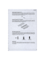
All Military Class III components have passed the following MIL-STD-810G tests
Low Pressure Test
- High Temperature Test
Low Temperature Test
- Temperature Shock Test
Humidity Test
- Vibration Test
Shock Test
• Military Class III Levels More Stars for Higher Ranks
Military Class III Level
I Solid CAP
5 Stars
* * * * *
•
4 Stars
* * * *
•
3 Stars * *
SFC
Hi-c CAP [ DrMOS II
•
•
•
*
www.msi.cor
MS-7592
FCC-B RADIO FREQUENCY INTERFERENCE STATEMENT
This equipment has been tested and found to comply with the limits for a class
В digital device, pursuant to part 15 of the FCC rules. These limits are designed
to provide reasonable protection against harmful interference in a residential
installation. This equipment
generates, uses and can
radiate radio frequency energy and, if not installed and used in accordance with
the instruction manual, may cause harmful interference to radio communications.
However, there is no guarantee that interference will occur in a particular installation. If this equipment does cause harmful interference to radio or television
reception, which can be determined by turning the equipment off and on, the user
is encouraged to try to correct the interference by one or more of the measures
listed below.
О N1996
•
Reorient or relocate the receiving antenna.
•
Increase the separation between the equipment and receiver.
•
Connect the equipment into an outlet on a circuit different from that to
which the receiver is connected.
Consult the dealer or an experienced radio/television technician for
help.
•
Notice 1
The changes or modifications not expressly approved by the party responsible for
compliance could void the user's authority to operate the equipment.
Notice 2
Shielded interface cables and AC power cord, if any, must be used in order to
comply with the emission limits.
VOIR LA NOTICE D'NSTALLA TION A VANT DE RACCORDER AU RESEAU.
F©
Micro-Star International
MS-7592
This device complies with Part 15 of the FCC Rules. Operation is subject to the
following two conditions:
1)
this device may not cause harmful interference, and
2)
this device must accept any interference received, including interference that
may cause undesired operation.
PART NUMBER
G52-75921XG-Q13
COPYRIGHT NOTICE
The material in this document is the intellectual property of MICRO-STAR INTERNATIONAL. We take every care in the preparation of this document, but no
guarantee is given as to the correctness of its contents. Our products are under
continual improvement and we reserve the right to make changes without notice.
TRADEMARKS
All trademarks are the properties of their respective owners.
• MSI® is registered trademark of Micro-Star Int'l Co.,Ltd.
• NVIDIA® is registered trademark of NVIDIA Corporation.
• ATI® is registered trademark of ATI Technologies, Inc.
• AMD® is registered trademarks of AMD Corporation.
• Intel® is registered trademarks of Intel Corporation.
• Windows® is registered trademarks of Microsoft Corporation.
• AMI® is registered trademark of Advanced Micro Devices, Inc.
• Award® is a registered trademark of Phoenix Technologies Ltd.
• Sound Blaster® is registered trademark of Creative Technology Ltd.
• Realtek® is registered trademark of Realtek Semiconductor Corporation.
• JMicron® is registered trademark of JMicron Technology Corporation.
• Netware® is a registered trademark of Novell, Inc.
REVISION HISTORY
1 Revision
Revision History
Date
V6.0
For PCB 6.x
February 2010
V6.1
For G41M-S03
April 2010
V6.2
For G41M-P23
April 2010
V6.3
For G41M-P25/ G41M-P23/
G41M-S02/ G41M-S03
April 2010
V6.4
Update JSP1 forG41M-P23
July 2010
V6.5
Update JSP1 for G41M-S03
July 2010
V6.6
Update JSP1 for G41M-P25/
G41M-S02
July 2010
MS-7592
SAFETY INSTRUCTIONS
• Always read the safety instructions carefully.
• Keep this User Manual for future reference.
• Keep this equipment away from humidity.
• Lay this equipment on a reliable flat surface before setting it up.
• The openings on the enclosure are for air convection hence protects the
equipment from overheating. Do not cover the openings.
• Make sure the voltage of the power source and adjust properly 110/220V
before connecting the equipment to the power inlet.
• Place the power cord such a way that people can not step on it. Do not place
anything over the power cord.
• Always Unplug the Power Cord before inserting any add-on card or module.
• All cautions and warnings on the equipment should be noted.
• Never pour any liquid into the opening that could damage or cause electrical shock.
• If any of the following situations arises, get the equipment checked by service
personnel:
°
The power cord or plug is damaged,
о
Liquid has penetrated into the equipment,
о
The equipment has been exposed to moisture.
о
The equipment does not work well or you can not get it work according
to User Manual,
о
The equipment has dropped and damaged,
о The equipment has obvious sign of breakage.
• Do not leave this equipment in an environment unconditioned, storage temperature above 60°C (140°F), it may damage the equipment.
CAUTION
Danger of explosion if battery is incorrectly replaced. Replace only with the same
or equivalent type recommended by the manufacturer.
шшршюжтхя
шят,
E3
, {Ет&ютяФтявФ,
шня+шшшжхшажшшо
wmwmтиття,
М Я М Ш г И К
For better environmental protection, waste batteries should be collected separately for recycling or special disposal.
WEEE STATEMENT
ENGLISH
To protect the global environment and as an environmentalist, MSI
must remind you that...
Under the European Union ("EU") Directive on Waste Electrical and
Electronic Equipment, Directive 2002/96/EC, which takes effect on
August 13, 2005, products of "electrical and electronic equipment"
cannot be discarded as municipal waste anymore and manufacturers of covered
electronic equipment will be obligated to take back such products at the end of
their useful life. MSI will comply with the product take back requirements at the
end of life of MSI-branded products that are sold into the EU. You can return
these products to local collection points.
DELTTSCH
Hinweis von MSI zur Erhaltung und Schutz unserer Umwelt
Gemalł der Richtlinie 2002/96/EG uber Elektro- und Elektronik-Altgerate diirfen Elektro- und Elektronik-Altgerate nicht mehr als kommunale Abfalle entsorgt
werden. MSI hat europaweit verschiedene Sammel- und Recyclingunternehmen
beauftragt, die in die Europaische Union in Verkehr gebrachten Produkte, am
Ende seines Lebenszyklus zuriickzunehmen. Bitte entsorgen Sie dieses Produkt
zum gegebenen Zeitpunkt ausschliesslich an einer lokalen Altgeratesammelstelle in Ihrer Nahe.
FRANQAIS
En tant qu'ecologiste et afin de proteger I'environnement, MSI tient a rappeler
ceci...
Au sujet de la directive europeenne (EU) relative aux dśchets des equipement
electriques et ślectroniques, directive 2002/96/EC, prenant effet le 13 aoiit 2005,
que les produits electriques et electroniques ne peuvent etre deposes dans les
decharges ou tout simplement mis a la poubelle. Les fabricants de ces equipements seront obliges de recuperer certains produits en fin de vie. MSI prendra
en compte cette exigence relative au retour des produits en fin de vie au sein de
la communaute europeenne. Par consequent vous pouvez retourner localement
ces materiels dans les points de collecte.
РУССКИЙ
Компания MSI предпринимает активные действия по защите окружающей
среды, поэтому напоминаем вам, что....
В соответствии с директивой Европейского Союза (ЕС) по предотвращению
загрязнения окружающей среды использованным электрическим и
электронным оборудованием (директива WEEE 2002/96/ЕС), вступающей
в силу 13 августа 2005 года, изделия, относящиеся к электрическому и
электронному оборудованию, не могут рассматриваться как бытовой мусор,
поэтому производители вышеперечисленного электронного оборудования
обязаны принимать его для переработки по окончании срока службы. MSI
обязуется соблюдать требования по приему продукции, проданной под
маркой MSI на территории ЕС, в переработку по окончании срока службы.
Вы можете вернуть эти изделия в специализированные пункты приема.
4
MS-7592
ESPAflOL
MSI como empresa comprometida eon la protección del medio ambiente,
recomienda:
Bajo la directive 2002/96/EC de la Union Europea en materia de desechos y/o
equipos electrónicos, con fecha de rigor desde el 13 de agosto de 2005, los
productos clasificados como "electricos у equipos electrónicos" no pueden ser
depositados en los contenedores habituales de su municipio, los fabricantes de
equipos electrónicos, estan obligados a hacerse cargo de dichos productos al
termino de su periodo de vida. MSI estara comprometido eon los terminos de
recogida de sus productos vendidos en la Unión Europea al final de su periodo
de vida. Usted debe depositar estos productos en el punto limpio establecido
por el ayuntamiento de su localidad o entregar a una empresa autorizada para
la recogida de estos residuos.
NEDERLANDS
Om het milieu te beschermen, wil MSI u eraan herinneren dat ...
De richtlijn van de Europese Unie (EU) met betrekking tot Vervuiling van Electrische en Electronische producten (2002/96/EC), die op 13 Augustus 2005 in
zal gaan kunnen niet meer beschouwd worden als vervuiling. Fabrikanten van
dit soort producten worden verplicht om producten retour te nemen aan het eind
van hun levenscyclus. MSI zal overeenkomstig de richtlijn handelen voor de producten die de merknaam MSI dragen en verkocht zijn in de EU. Deze goederen
kunnen geretourneerd worden op lokale inzamelingspunten.
SRPSKI
Da bi zaśtitili prirodnu sredinu, i kao preduzeće koje vodi raćuna o okolini i
prirodnoj sredini, MSI mora da vas podesti da...
Po Direktivi Evropske unije ("EU") o odbaćenoj ekektronskoj i elektricnoj opremi, Direktiva 2002/96/EC, koja stupa na snagu od 13. Avgusta 2005, proizvodi
koji spadaju pod "elektronsku i elektrićnu opremu" ne mogu viśe biti odbaćeni
kao obićan otpad i proizvodaći ove opreme biće prinudeni da uzmu natrag ove
proizvode na kraju njihovog uobićajenog veka trajanja. MSI će pośtovati zahtev
o preuzimanju ovakvih proizvoda kojima je istekao vek trajanja, koji imaju MSI
oznaku i koji su prodati u EU. Ove proizvode możete vratiti na lokalnim mestima
za prikupljanje.
POLSK]
Aby chronić nasze środowisko naturalne oraz jako firma dbająca o ekologię,
MSI przypomina, że...
Zgodnie z Dyrektywą Unii Europejskiej ("UE") dotyczącą odpadów produktów
elektrycznych i elektronicznych (Dyrektywa 2002/96/EC), która wchodzi w życie
13 sierpnia 2005, tzw. "produkty oraz wyposażenie elektryczne i elektroniczne " nie mogą być traktowane jako śmieci komunalne, tak więc producenci
tych produktów będą zobowiązani do odbierania ich w momencie gdy produkt
jest wycofywany z użycia. MSI wypełni wymagania UE, przyjmując produkty
(sprzedawane na terenie Unii Europejskiej) wycofywane z użycia. Produkty MSI
będzie można zwracać w wyznaczonych punktach zbiorczych.
TORKQE
Qevreci ózelligiyle bilinen MSI dunyada ęevreyi korumak ięin hatirlatir:
Avrupa Birligi (AB) Kararnamesi Elektrik ve Elektronik Malzeme Atigi, 2002/96/
EC Kararnamesi altinda 13 Agustos 2005 tarihinden itibaren geęerli olmak
iizere, elektrikli ve elektronik malzemeler diger atiklar gibi ęópe atilamayacak
ve bu elektonik cihazlarin ureticileri, cihazlarin kullanim sOreleri bittikten sonra
iiriinleri geri toplamakla yukumlti olacaktir. Avrupa Biriigi'ne satilan MSI markali
lirunlerin kullanim sureleri bittiginde MSI urunlerin geri alinmasi istegi ile iębirligi
ięerisinde olacaktir. Urunlerinizi yerel toplama noktalarina birakabilirsiniz.
ĆESKY
Zależi nam na ochranę zivotniho prostfedi - spolećnost MSI upozorńuje...
Podle smśrnice Evropske unie ("EU") o likvidaci elektrickych a elektronickych
vyrobku 2002/96/EC płatne od 13. srpna 2005 je zakazano likvidovat "elektricke
a elektronickś vyrobky" v bśźnem komunalnim odpadu a vyrobci elektronickych vyrobku, na ktere se tato smśrnice vztahuje, budou povinni odebirat takove
vyrobky zpśt po skonćeni jejich zivotnosti. Spolećnost MSI splni pozadavky na
odebirani vyrobku znaćky MSI, prodavanych v zemich EU, po skonćeni jejich
zivotnosti. Tyto vyrobky miiżete odevzdat v mistnich sbśrnach.
MAGYAR
Annak erdekeben, hogy kornyezetunket megvedjuk, illetve kornyezetvedokent
fellepve az MSI emlekezteti 6nt, hogy ...
Az Európai Unió („EU") 2005. augusztus 13-an hatalyba lepó, az elektromos
es elektronikus berendezesek hulladekairól szóló 2002/96/EK iranyelve szerint
az elektromos es elektronikus berendezesek tóbbe nem kezelhetóek lakossagi
hulladekkent, es az ilyen elektronikus berendezesek gyartói kótelesse valnak az
ilyen termekek visszavetelere azok hasznos elettartama vegen. Az MSI betartja
a termekvisszavetellel kapcsolatos kovetelmenyeket az MSI markanev alatt az
EU-n beliil ertekesitett termekek eseteben, azok elettartamanak vegen. Az ilyen
termekeket a legkózelebbi gyujtóhelyre viheti.
ITAL1ANO
Per proteggere I'ambiente, MSI, da sempre arnica delia natura, ti ricorda
che....
In base alia Direttiva dell'Unione Europea (EU) sullo Smaltimento dei Materiali Elettrici ed Elettronici, Direttiva 2002/96/EC in vigore dal 13 Agosto 2005,
prodotti appartenenti alia categoria dei Materiali Elettrici ed Elettronici non possono piu essere eliminati come rifiuti municipali: i produttori di detti materiali
saranno obbligati a ritirare ogni prodotto alia fine del suo ciclo di vita. MSI si
adeguera a tale Direttiva ritirando tutti i prodotti marchiati MSI che sono stati
venduti all'interno dell'Unione Europea alia fine del loro ciclo di vita. Ё possibile
portare i prodotti nel piu vicino punto di raccolta
MS-7592
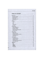
TABLE OF CONTENT
ENGLISH
9
GETTING STARTED
9
SPECIFICATIONS
Ю
REAR PANEL
12
HARDWARE SETUP
12
BIOS SETUP
22
tR<H
27
A|5f 8 f 7 |
Afgf
27
28
30
30
BIOS tf S
40
FRANQAIS
45
POUR COMMENCER
45
SPECIFICATIONS
46
PANNEAU ARRltRE
48
INSTALLATION DU MATERIEL
48
REGLAGE BIOS
58
DEUTSCH
63
EINLEITUNG
63
SPEZIFIKATIONEN
64
HINTERES ANSCHLUSSPANEL
66
HARDWARE SETUP
66
BIOS SETUP
76
РУССКИЙ
81
НАЧАЛО РАБОТЫ
81
ХАРАКТЕРИСТИКИ
82
ЗАДНЯЯ ПАНЕЛЬ
84
УСТАНОВКА ОБОРУДОВАНИЯ
84
НАСТРОЙКА BIOS
94
101
ffi^
101
Ш
102
104
-
BIOS « Ж
104
114
ЖвФЛ
119
119
ЯШ
120
W®
122
«Я&Й
122
BIOS Й Й
ВФИ
ttlTfelC
132
137
I / O A * Л.
Д - P O i T i z v ЬТ-УУ
137
138
140
140
Biosroiss
150
MS-7592
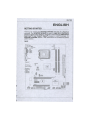
ENGLISH
GETTING STARTED
Thank you for choosing the G41M-P25/ G41M-S02 (MS-7592 v6.x) Micro-ATX
mainboard. The G41M-P25/ G41M-S02 is based on Intel* G41 & ICH7flCH7R
chipset for optimal system efficiency. Designed to fit the advanced Intel* Core™2
Quad/ Core™2 Duo/ Pentium*/ Celeron* processor in LGA775 package, the
G41M-P25/ G41M-S02 delivers a high performance and professional desktop
platform solution.
Layout
2
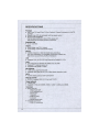
SPECIFICATIONS
Processor
• Intel® Core™2 Quad/ Core™2 Duo/ Pentium®/ Celeron® processor in LGA775
package
• Support 4-pin CPU fan pinheader with fan speed control
• Support FMB 05a@95W
(For the latest information about CPU, please visit
http://www.msi.com/index.php?func=cpuform2)
Supported FSB
• Up to 1333 MHz
Chipset
• North Bridge: Intel® G41 chipset
• South Bridge: Intel® ICH7/ICH7R chipset
Memory
• 2 DDR3 1333(OC)/1066/ 800 DIMM slots (8GB Max)
(For more information on compatible components, please visit
http://www. msi. com/index.php ?func=testreport)
LAN
• Supports LAN 10/100/1000 Fast Ethernet by Realtek® 8111DL
Audio
• Chip integrated by Realtek® ALC888S VC2/ ALC889
• Supports 7.1 channels audio out
•
Compliant with Azalia 1.0 Spec
IDE (optional)
• 1 IDE port by Intel® ICH7/ICH7R
•
Supports Ultra DMA 66/100, PIO & Bus Master operation mode
SATA
•
4 SATA 3Gb/s ports by Intel® ICH7/ICH7R
RAID
(for ICH7R)
• SATA1-4
support RAID 0/1/10 by Intel® ICH7R
Floppy (optional)
• 1 floppy port
• Supports 1 FDD with 360KB, 720KB, 1.2MB, 1.44MB and 2.88MB
Connectors
• Back Panel I/O
- 1 PS/2 mouse port
- 1 PS/2 keyboard port
- 1 DVI-D port
- 1 VGA port
- 4 USB 2.0 ports
- 1 LAN jack
- 6 flexible audio jacks
• Onboard Connectors
- 2 USB 2.0 connectors
10
MS-7592
-
1 S/PDIF-Out connector
1 CD-ln connector (optional)
1 front audio connector
1 chassis Intrusion connector
1 parallel connector (optional)
1 serial port connecotr (optiobal)
1 TPM connector
-
1 ОС switch (optional)
Slots
• 1 PCI Express x16 slot
• 1 PCI Express x1 slot
•
1 PCI slot, supports 3.3V/ 5V PCI bus Interface
Form Factor
•
Micro-ATX (200mm x 244mm)
Mounting
• 6 mounting holes
If you need to purchase accessories and request the part numbers, you could
search the product web page and find details on our web address below
http-.Uwww. msi. com/index.php
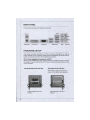
REAR PANEL
The rear panel provides the following connectors:
Keyboard
DVI-D Port
VGA Port
USB Ports
MIC
SS-Out
HARDWARE SETUP
This section provides instructions on CPU and memory installation, as well as
jumper settings on the mainboard. While doing the installation, be careful in holding the components and follow the installation procedures.
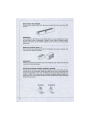
CPU & Cooler Installation Procedures for LGA775
When you are installing the CPU, make sure that you install the cooler to prevent
overheating. If you do not have the CPU cooler, consult your dealer before turning
on the computer.
Tbe pin-pad side of LGA 775 CPU
The surface of LGA 775 CPU
Remember to apply some thermal
paste on it for better heat dispersion.
w
m
Yellow triangle is the Pin 1
indicator
I ^Alignment К е у ^ Д
Yellow triangle is the Pin 1
indicator
MS-7592
Follow the steps below to install the CPU & cooler correctly. Wrong installation will
cause the damage of your CPU & mainboard.
1.
The CPU socket has a plastic cap on it to protect
the contact from damage. Before you install the
CPU, always cover it to protect the socket pins.
2.
Remove the cap from the lever hinge side.
3.
The pins of socket reveal.
4.
Open the load lever.
5.
Lift the load lever up and open the load plate.
6.
After confirming the CPU direction for correct mating, put down the CPU in the socket housing frame.
Be sure to grasp on the edge of the CPU base.
Note that the alignment keys are matched.
7.
Visually inspect if the CPU is seated well into the
socket. If not, take out the CPU with pure vertical
motion and reinstall.
8.
Cover the load plate onto the package.
9.
Press down the load lever lightly onto the load
plate, and then secure the lever with the hook under the retention tab.
10. Align the holes on the mainboard with the heatsink.
Push down the cooler until its four clips get wedged
into the holes of the mainboard.
11. Press the four hooks down to fasten the cooler.
Then rotate the locking switch (refer to the correct
direction marked on it) to lock the hooks.
12. Turn over the mainboard to confirm that the clipends are correctly inserted.
13. Finally, attach the CPU Fan cable to the CPU fan
connector on the mainboard.
IMPORTANT
* Read the CPU status in BIOS.
Whenever the CPU is not installed, always protect your CPU socket pins with
the plastic cap covered.
Mainboard photos shown in this section are for demonstration of the CPU/cooler
installation only. The appearance of your mainboard may vary depending on the
model you purchase.
2
Installing Memory Modules
1. The memory module has only one notch on the center and will only fit in the
right orientation.
2.
Insert the memory module vertically into the DIMM slot. Then push it in until
the golden finger on the memory module is deeply inserted in the DIMM slot.
The plastic clip at each side of the DIMM slot will automatically close when the
memory module is properly seated. You can barely see the golden linger If the
memory module Is property Inserted In the DIMM slot
3.
Manually check if the memory module has been locked in place by the DIMM
slot clips at the sides.
* In Dual-Channel mode, make sure that you install memory modules of the same
type and density in different channel DIMM slots.
' To enable successful system boot-up, always insert the memory modules into
the DIMM1 first.
MS-7592
ATX 24-Pln Power Connector JPWR1
This connector allows you to connect an ATX 24-pin power supply. To connect the
ATX 24-pin power supply, make sure the plug of the power supply is inserted in
the proper orientation and the pins are aligned. Then push down the power supply
firmly into the connector.
ATX 4-Pln Power Connector JPWR2
This 4-Pin power connector is used to provide power to the CPU.
IMPORTANT
' Make sure that all the connectors are connected to proper ATX power supplies
to ensure stable operation of the mainboard.
* Power supply of 350 watts (and above) is highly recommended for system stability.
Floppy Disk Drive Connector FDD1 (optional)
This connect or supports 360KB, 720KB, 1.2MB, 1.44MB or 2.88MB floppy disk
drive.
2
IDE Connector. IDE1 (optional)
This connector supports IDE hard disk drives, optical disk drives and other IDE
devices.
IMPORTANT
If you install two IDE devices on the same cable, you must configure the drives
to cable select mode or separately to master / slave mode by setting jumpers.
Refer to IDE device documentation supplied by the vendors for jumper setting
instructions.
Serial ATA Connector. SATA1 - 4
This connector is a high-speed Serial ATA interface port. Each connector can
connect to one Serial ATA device.
IMPORTANT
Please do not fold the Serial ATA cable into 90-degree angle. Otherwise, data loss
may occur during transmission.
Fan Power Connectors: CPUFAN1, SYSFAN1, SYSFAN2
The fan power connectors support system cooling fan with +12V. When connecting the wire to the connectors, always note that the red wire is the positive and
should be connected to the +12V; the black wire is Ground and should be connected to GND. If the mainboard has a System Hardware Monitor chipset onboard, you must use a specially designed fan with speed sensor to take advantage
of the CPU fan control.
CPUFAN1
16
SYSFAN1/2
MS-7592
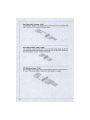
S/PDIF-Out Connector SPDOUT1
This connector is used to connect S/PDIF (Sony & Philips Digital Interconnect
Format) interface for digital audio transmission.
CD-ln Connector JCD1 (optional)
This connector is provided for external audio input.
Front Panel Connectors: JFP1, JFP2
These connectors are for electrical connection to the front panel switches and
LEDs. The JFP1 is compliant with Intel® Front Panel I/O Connectivity Design
Guide.
Serial Port Connector JCOM1 (optional)
This connector is a 16550A high speed communication port that sends/receives
16 bytes FIFOs. You can attach a serial device.
Front Panel Audio Connector JAUD1
This connector allows you to connect the front panel audio and is compliant with
Intel® Front Panel I/O Connectivity Design Guide.
Front USB Connector JUSB1, JUSB2
This connector, compliant with Intel® I/O Connectivity Design Guide, is ideal for
connecting high-speed USB interface peripherals such as USB HDD, digital cam-
TPM Module connector JTPM1
This connector connects to a TPM (Trusted Platform Module) module. Please refer to the TPM security platform manual for more details and usages.
MS-7592
Chassis Intrusion Connector JCI1
This connector connects to the chassis intrusion switch cable. If the chassis is
opened, the chassis intrusion mechanism will be activated. The system will record
this status and show a warning message on the screen. To clear the warning, you
must enter the BIOS utility and clear the record.
Parallel Port Header JLPT1 (optional)
This connector is used to connect an optional parallel port bracket. The parallel
port is a standard printer port that supports Enhanced Parallel Port (EPP) and
Extended Capabilities Parallel Port (ECP) mode.
Clear CMOS Jumper JBAT1
There is a CMOS RAM onboard that has a power supply from an external battery
to keep the data of system configuration. With the CMOS RAM, the system can
automatically boot OS every time it is turned on. If you want to clear the system
configuration, set the jumper to clear data.
JBAT1
| • ! 41
Keep Data
Clear Data
IMPORTANT
You can clear CMOS by shorting 2-3 pin while the system is off. Then return to
1-2 pin position. Avoid clearing the CMOS while the system is on; it will damage
the mainboard.
19
i
Overckx* FSB Switch: OC_SW1 (optional)
You can overclock the FSB to increase the processor frequency by changing the
switch. Follow the instructions below to set the FSB.
ON
ON
1 2 3
1 2 3
Default
200-»266 MHz
BUB BBB
ON
BBB
1 2 3
ON
ВУУ
1 2 3
200-»333 MHz 266-»333 MHz
IMPORTANT
' Make sure that you power off the system before setting the switch.
* When overciocking cause system instability or crash during boot, please set the
switch to default setting.
MS-7592
PCI Express Slot
The PCI Express slot supports the PCI Express interface expansion card.
PCI Express x16 slot.
PCI Express x1 slot.
PCI Slot
The PCI slot supports LAN card, SCSI card, USB card, and other add-on cards
that comply with PCI specifications.
IMPORTANT
When adding or removing expansion cards, make sure that you unplug the power
supply first. Meanwhile, read the documentation for the expansion card to configure any necessary hardware or software settings for the expansion card, such as
jumpers, switches or BIOS configuration.
PCI Interrupt Request Routing
The IRQ, acronym of interrupt request line and pronounced l-R-Q, are hardware
lines over which devices can send interrupt signals to the microprocessor. The PCI
IRQ pins are typically connected to the PCI bus pins as follows:
Order
Slot
PCI 1
1
2
3
4
INT A#
INT B#
INT C#
INT D#
2
BIOS SETUP
Power on the computer and the system will start POST (Power On Self Test)
process. When the message below appears on the screen, press <DEL> key to
enter Setup.
Press DEL to enter SETUP
If the message disappears before you respond and you still wish to enter Setup,
restart the system by turning it OFF and On or pressing the RESET button. You
may also restart the system by simultaneously pressing <Ctrl>, <Alt>, and <Delete> keys.
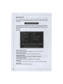
Main Page
CUB Setup lit 111 tij
C a n r i f M (С) 14IS 2865. йяегiran IVgaliend-.. I n
• Standard MIS Features
* Cell IVini
• Muanced BHIS Features
I • 1 Flash
• Integrated Peripherals
I
I
I Fall Safe Defaults
• Powei Haiiaiieneiil Setup
Load Optlni/ed Detail I Is
• H/ll Ibmitar
Save Я Exit Setup
I (ireenPuwei
Exit Uithuut Saving^
HII1S Setting PassMord
tl—:lto»e Enter Select •/ / Ualue F10:Saue ESC Exit F1 General Help
F4:CPU Z
R:lfe«org Z
FHiFail Safe Defaults
Fl. llptiai/ed Detail
Configure T м and Date.
Display Sgstea IufuiNation...
U02.61 (C>Copyright Г«Ь 20%. ftaerican Ifegatrends. Inc.
Standard CMOS Features
Use this menu for basic system configurations, such as time, date etc.
Advanced BIOS Features
Use this menu to setup the items of special enhanced features.
Integrated Peripherals
Use this menu to specify your settings for integrated peripherals.
Power Management Setup
Use this menu to specify your settings for power management.
H/W Monitor
This entry shows the status of your CPU, fan, warning for overall system status.
Green
Use thisPower
menu to specify the power phase.
22
MS-7592
BIOS Setting Password
Use this menu to set BIOS setting Password.
Cell Menu
Use this menu to specify your settings for frequency/voltage control.
M-Flash
Use this menu to read/ flash the BIOS from USB media device.
Load Fail-Safe Defaults
Use this menu to load the BIOS default values that are factory settings for system
operations.
Load Optimized Defaults
Use this menu to load factory default settings into the BIOS for stable system
performance operations.
Save & Exit Setup
Save changes to CMOS and exit setup.
Exit Without Saving
Abandon all changes and exit setup.
Cell Menu
> cm Sper iTicAtInns
Intel EI SI
Hdjuut CPU FSB Fl equei
fid just CPU Katio
(Ыjuried CPU Fini(iifi*:i
!№)
UtóiH Frequency (ГШ/)
IPress Enter I
(Enable!)
Ш1
10№
ИКПП Uoltdge(U)
Ш1 Uli I tdye (U)
CPU UTICU)
CPU UulU|e<U>
Current CPU/DRAM Frequency
It shows the current frequency of CPU/Memory. Read-only.
CPU Specifications
Press <Enter> to enter the submenu, that shows the information of installed
CPU.
2:
CPU Technology Support
Press <Enter> to enter the submenu, that shows the technologies that the installed CPU supported.
Intel EIST
The Enhanced Intel SpeedStep technology allows you to set the performance
level of the microprocessor whether the computer is running on battery or AC
power. This field will appear after you installed the CPU which support SpeedStep
technology.
Adjust CPU FSB Frequency (MHz)
This item allows you to adjust the CPU FSB frequency.
Adjust CPU Ratio
This item is used to adjust CPU clock multiplier (ratio). It is available only when the
processor supports this function.
Adjusted CPU Frequency (MHz)
It shows the adjusted CPU frequency (FSB x Ratio). Read-only.
MEMORY-Z
Press <Enter> to enter the submenu.
DIMM1/2 Memory SPD Information
Press <Enter> to enter the submenu, that displays the informations of installed
memory.
Advance DRAM Configuration
Press <Enter> to enter the submenu.
DRAM Timing Mode
Selects whether DRAM timing is controlled by the SPD (Serial Presence Detect) EEPROM on the DRAM module. Setting to [Auto By SPD] enables DRAM
timings and the following related items to be determined by BIOS based on the
configurations on the SPD. Selecting [Manual] allows users to configure the
DRAM timings and the following related items manually.
CAS Latency (CL)
When the DRAM Timing Mode sets to [Manual], the field is adjustable. This
controls the CAS latency, which determines the timing delay (in clock cycles)
before SDRAM starts a read command after receiving it.
tRCD
When the DRAM Timing Mode sets to [Manual], the field is adjustable. When
DRAM is refreshed, both rows and columns are addressed separately. This
setup item allows you to determine the timing of the transition from RAS (row
address strobe) to CAS (column address strobe). The less the clock cycles, the
faster the DRAM performance.
tRP
When the DRAM Timing Mode sets to [Manual], the field is adjustable. This
item controls the number of cycles for Row Address Strobe (RAS) to be allowed to precharge. If insufficient time is allowed for the RAS to accumulate its
charge before DRAM refresh, refreshing may be incomplete and DRAM may
24
MS-7592
fail to retain data. This item applies only when synchronous DRAM is installed
in the system.
tRAS
When the DRAM Timing Mode sets to [Manual], the field is adjustable. This setting determines the time RAS takes to read from and write to a memory cell.
tRTP
When the DRAM Timing Mode sets to [Manual], the field is adjustable. Time
interval between a read and a precharge command.
tRFC
When the DRAM Timing Mode sets to [Manual], the field is adjustable. This setting determines the time RFC takes to read from and write to a memory cell.
tWR
When the DRAM Timing Mode is set to [Manual], the field is adjustable. It specifies the amount of delay (in clock cycles) that must elapse after the completion
of a valid write operation, before an active bank can be precharged. This delay
is required to guarantee that data in the write buffers can be written to the
memory cells before precharge occurs.
tRRD
When the DRAM Timing Mode sets to [Manual], the field is adjustable. Specifies the active-to-active delay of different banks.
tWTR
When the DRAM Timing Mode is set to [Manual], the field is adjustable. This
item controls the Write Data In to Read Command Delay memory timing. This
constitutes the minimum number of clock cycles that must occur between the
last valid write operation and the next read command to the same internal bank
of the DDR device.
FSB/DRAM Ratio
This item will allow you to adjust the ratio of FSB to memory.
Adjusted DRAM Frequency (MHz)
It shows the adjusted memory frequency. Read-only.
Adjust PCI-E Frequency (MHz)
This item allows you to adjust the PCI-E frequency.
Auto Disable DRAM/PCI Frequency
When set to [Enabled], the system will remove (turn off) clocks from empty DIMM
and PCI slots to minimize the electromagnetic interference (EMI).
DRAM Voltage (V), NB Voltage (V), CPU VTT (V), CPU Voltage (V)
These items are used to adjust the voltage of CPU, Memory and chipset.
Spread Spectrum
When the motherboard's clock generator pulses, the extreme values (spikes) of
the pulses create EMI (Electromagnetic Interference). The Spread Spectrum function reduces the EMI generated by modulating the pulses so that the spikes of
the pulses are reduced to flatter curves. If you do not have any EMI problem,
leave the setting at Disabled for optimal system stability and performance. But if
2
you are plagued by EMI, set to Enabled for EMI reduction. Remember to disable
Spread Spectrum if you are overclocking because even a slight jitter can introduce
a temporary boost in clock speed which may just cause your overclocked processor to lock up.
IMPORTANT
* If you do not have any EMI problem, leave the setting at [Disabled] for optimal
system stability and performance. But if you are plagued by EMI, select the
value of Spread Spectrum for EMI reduction.
* The greater the Spread Spectrum value is, the greater the EMI is reduced, and
the system will become less stable. For the most suitable Spread Spectrum
value, please consult your local EMI regulation.
* Remember to disable Spread Spectrum if you are overclocking because even a
slight jitter can introduce a temporary boost in clock speed which may just cause
your overclocked processor to lock up.
Load Optimized Defaults
You can load the default values provided by the mainboard manufacturer for the
stable performance.
UKIS Setup U t l l i t g
Copyright Ю 1HIS Л » . . ffcerlcan Itegatiends. Inc.
Load Optinal Default values for a l l the setup questions.
и02.Ы (С)Copyright | Ж Ж .
26
ftaerican Begatrends. Inc.
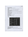
M-FLASH SETUP
M-Flash funcion allows you to flash BIOS from USB drive/ storage drive (FAT/ FAT32
format only), or allows the system to boot from the BIOS file inside USB drive (FAT/
FAT32 format only). To use M-Flash, first boot/reboot the computer and the system will
start POST (Power On Self Test) process. When the message below appears on the
screen, press <DEL> key to enter BIOS.
Press DEL to enter SETUP
Select M-Flash in BIOS main menu and press <ENTER> key to enter M-Flash menu
and the following menu appears.
CH0S Setup U t i l i t y
Copyright
(C) 1985 2005, American Неудtrend'.,
H-Flash
= BIOS Update or Boot 2nd BIOS Fron USB driue ==
tl-Flash function as
[Disabled]
= = = = = Backup BIOS t o USB driue = = = = =
Sage F i l e t o Selected Deuice [USB:USB FD1
Saue F i l e Name as
Sage Extend F i l e nai
Start t o saue f i l e
[BIOS!
11131
[Press Enter]
Inc.
(BIOS Update]: Update
BIOS RUtl Chip data
f r o * selected f i l e .
[Boot]: After
a l l o c a t e d BIOS f i l e .
Systen u i l l boot fron
t h i s BIOS uhich stored
a t USB Drige.
Ti«"»:Moge E n t e r : S e l e c t
»/-/:Ualue F10:Sage ESC:Exit Fl:Genera] Help
F4:CPU Spec F5:Hetnory-Z F 8 : F a i l - S a f e D e f a u l t s F6Optimized D e f a u l t s
Please refer to the instructions below to setup.
== BIOS Update or Load BIOS From USB drive==
M П—h function as
[Disabled]
Disable M-Flash function.
[BIOS Update]
Flash BIOS via the USB/ Storage drive directly. Update BIOS
ROM chip data from selected file, which is download from official website and must be saved in the root directory of the USB/
Storage drive. It only supports particular file name, which is the
official BIOS file name from us.
[Boot]
After allocated particular BIOS file, system will boot from this
BIOS file which saved in the root directory of USB drive. System
will skip MB ROM chip data and boot with thisparticular BIOS
inside USB drive.Note: this option is for USB drive only.
G52-XXXX22B-Q13
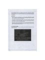
IMPORTANT
* Please refer to the block diagram below about the M-Flash function.
i
Select BIOS file from the root directory of
USB/ Storage drive (FAT/FAT32 format only)
in "Load BIOS source file from" field
Please check USB drive/
Storage drive/ BIOS file
status and reboot the
system manually again.
Start M-Flash
I 4 short beeps
BIOS update successfully
Boot from the USB drive successfully
* Due to the special design of some graphics cards will cause dark screen during Mflash operation, and you may refer the beeps from the system to confirm the current
M-flash process.
== BIOS Data Saving ==
The following fields are used to read the onboard BIOS ROM data, and save it to USB
drive/ storage drive.
Save File to Selected Device
Please setup a specific folder in specific USB drive/ storage drive to save BIOS file
from BIOS ROM chip data. Note: it only supports FAT/ FAT32 file system drive.
Save File Name as
Please setup a specific name for the BIOS file, which will be saved into the USB drive/
storage drive. Note: we suggest you using the official name as the default name.
Save Extend File name as
Please setup a specific extend name for the BIOS file, which will be saved into the USB
drive/ storage drive. Note: we suggest you using [ROM] as default name.
Start to save file
Press "Enter" and select "OK" the system will stare to save the onboard ROM chip data
to the selected USB drive/ storage drvie.