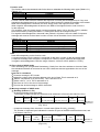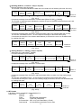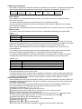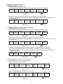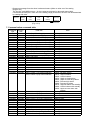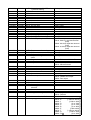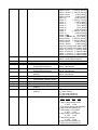
1
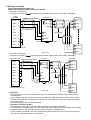
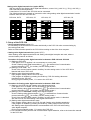
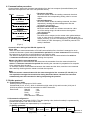
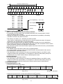
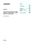
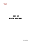
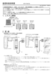
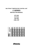
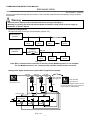
COMMUNICATION INSTRUCTION MANUAL
PCD-33A (C5, SVTC)
No.PCD3CE1 2003.02
To prevent accidents arising from the misuse of this controller, please ensure the operator using it receives
this manual.
Warning
Turn the power supply to the instrument off before wiring or checking it.
Working or touching the terminal with the power switched on may result in severe injury or
death due to Electric Shock.
1. System configuration
RS-485 multi-drop connection communication (Option: C5)
Host computer
RS-485
PCD-33A
No.0
PCD-33A
No.1
PCD-33A
No.2
PCD-33A
No.30
(Fig. 1-1)
Host computer
RS-232C
Communication
converter
IF-300-C5
232C
485
RS-485
PCD-33A
No.0
PCD-33A
No.1
PCD-33A
No.30
(Fig. 1-2)
Note: When communication converter IF-300-C5 is used, Modbus protocol is not available.
For the Modbus protocol, use a commercially available communication converter.
Setting value digital transmission (option SVTC) application example
RS-485
RS-485
RS-485
Input
Input
Input
JCR-33A-S/M
with option C5
PCD-33A-R/M
with option SVTC
Output
Thermocouple
Output
SSR
SSR
Thermocouple
Thermocouple
SSR
Confectionery
Heater
Heater
Output
Heater
(Fig. 1-3)
1
PCD-33A-S/M
with option C5
If Setting value digital reception function
is used, the PCD-33A can be used as a
slave instead of JCR-33A-S/M.
2. Wiring connection
Serial communication (option C5)
When using communication converter IF-300-C5
• Connector: D sub 25-pin
Connection: RS-232C
RS-485 (Communication speed: 2400, 4800, 9600, 19200bps)
Host
computer
120
IF-300-C5
built-in terminator
PCD-33A
TXD
2
YA (-) 2
11 YA (-)
RXD
3
YB (+) 1
14 YB (+)
SG
7
COM 11
FG
1
RTS
4
6 RX
CTS
5
5 TX
DSR
6
4 COM
Shield wire
DTR 20
CD
17 SG
Shield wire
RS-232C
RS-485
8
11 YA (-)
D sub connector 25-pin
14 YB (+)
17 SG
(Fig. 2-1)
• Connector: D sub 9-pin
Connection: RS-232C
Host computer
120
RS-485 (Communication speed: 2400, 4800, 9600, 19200bps)
built-in terminator
IF-300-C5
PCD-33A
TXD
3
YA (-) 2
11 YA (-)
RXD
2
YB (+) 1
14 YB (+)
GND
5
COM 11
DCD
1
DTR
4
6 RX
DSR
6
5 TX
RTS
7
4 COM
CTS
8
RI
9
17 SG
Shield wire
Shield wire
RS-232C
RS-485
11 YA (-)
14 YB (+)
D sub connector 9-pin
(Fig. 2-2)
17 SG
Shield wire
Connect only one side of the shield wire to the FG or GND terminal so that current cannot flow to
the shield wire.
(If both sides of the shield wire are connected to the FG or GND terminal, the circuit will be closed
between the shield wire and the ground. As a result, current will run through the shield wire and this
may cause noise.)
Never fail to ground FG and GND terminals.
Terminator (Terminal resistor)
Communication converter IF-300-C5 (sold separately) has a built-in terminator.
The terminator is mounted at the end of the wire when connecting a personal computer with multiple
peripheral devices. The terminator prevents signal reflection and disturbance.
Do not connect a terminator with the communication line because the PCD-33A has built-in pull-up
and pull-down resistors instead of a terminator.
2
Setting value digital transmission (option SVTC)
With the wiring of the Setting value digital transmission, connect YA (-) with YA (-), YB (+) with YB (+)
and COM with COM respectively.
A maximum of 31 units of the JCR-33A can be connected.
The following shows an example of connection when using setting value digital transmission function
between the PCD-33A and JCR-33A
PCD-33A, SVTC
JCR-33A, C5
JCR-33A, C5
JCR-33A, C5
11
11
11
11
12
12
12
12
13
13
13
13
14
14
14
14
15
15
15
15
16
16
16
16
17
17
17
17
18
18
18
18
19
19
19
19
20
20
20
20
3. Setup of the PCD-33A
(Fig. 2-3)
• Serial communication (option C5)
It is necessary to set an instrument number individually to the PCD-33A when communicating by
connecting plural units.
Select a communication speed for the PCD-33A according to that of the host computer.
• Setting value digital transmission (option SVTC)
When Setting value digital transmission and Setting value digital reception are used, select a
communication protocol as follows.
Procedure for Setting value digital transmission between PCD-33A and JCR-33A
(1) Setting to PCD-33A
If the option SVTC is applied, it is not necessary to set any item.
] is selected from Communication
Check if Setting value digital transmission [
] in Auxiliary function setting mode 1.
protocol selection [
(2) Setting to JCR-33A
Check if the communication speed in Auxiliary function setting mode 1 of the JCR-33A is
identical with that of PCD-33A.
(3) Setting value digital transmission starts.
Input program setting value to the PCD-33A.
If the program is initiated by pressing the RUN key, PCD-33A setting values are
transmitted to the JCR-33A.
During program standby mode, “0” is sent to the JCR-33A
Procedure for Setting value digital transmission between PCD-33As
(1) Setting to the PCD-33A with Setting value digital transmission
If the option SVTC is added, it is not necessary to set any item.
] is selected from Communication
Check if Setting value digital transmission [
] in Auxiliary function setting mode 1.
protocol selection [
(2) Setting to the PCD-33A with Setting value digital reception
] is selected from Communication
Check if Setting value digital reception [
] in Auxiliary function setting mode 1.
protocol selection [
Check if the communication speed in Auxiliary function setting mode 1 is identical
with that of PCD-33A with Setting value digital transmission.
(3) Setting value digital transmission starts.
Input program setting value to the PCD-33A with Setting value digital transmission.
If the program is initiated by pressing the RUN key, setting values of the PCD-33A
with Setting value digital transmission are transmitted to the PCD-33A with Setting
value digital reception.
During program standby mode, “0” is sent to the PCD-33A.
• For the Communication protocol and Communication speed selection, refer to the Instruction manual
for the PCD-33A.
3
4. Communication procedure
Communication starts with command transmission from the host computer (hereafter Master) and
ends with the response of the PCD-33A (hereafter Slave).
Master
Command
Data
Slave
Command
Acknowledgement
Command
Negative
acknowledgement
Command
No response
• Response with data
When the master sends the reading command, the slave
responds with the corresponding setting value or current
status.
• Acknowledgement
When the master sends the setting command, the slave
responds by sending the acknowledgement after the
processing is terminated.
• Negative acknowledgement
When the master sends non-existent command or value
out of the setting range, the slave returns the negative
acknowledgement.
• No response
The slave will not respond to the master when global address
is set, or when there is a framing error or checksum error (for
Shinko protocol), or when LRC discrepancy (for Modbus protocol
ASCII mode) or CRC discrepancy (for Modbus protocol RTU
mode) is detected.
(Fig.4-1)
Communication timing of the RS-485 (option C5)
Slave side
When the slave starts transmission to RS-485 communication line, the slave is arranged so as to
provide an idle status (mark status) transmission period of 1 or more characters before sending
the response to ensure the synchronization on the receiving side.
The slave is arranged so as to disconnect the transmitter from the communication line within a
1 character transmission period after sending the response.
Master side (Notice on programming)
Set the program so that the master can disconnect the transmitter from the communication line
within a 1 character transmission period after sending the command in preparation for reception
of the response from the slave.
To avoid the collision of transmissions between the master and the slave, send the next command
after carefully checking that the master received the response.
Note:
When the master communicates with the slave through the line converter (IF-300-C5), it is
not required to manage the transmission timing described above, because the converter
automatically sets the transmission timing interpreting the protocol.
5. Shinko protocol
5.1 Transmission mode
Shinko protocol is composed of ASCII codes.
Hexadecimal (0 to 9, A to F), which is divided into high order (4-bit) and low order (4-bit) out of
8-bit binary data in command is transmitted as ASCII characters.
Data format
Start bit
: 1 bit
Data bit
: 7 bits
Parity
: Even
Stop bit
: 1 bit
Error detection : Checksum
5.2 Command configuration
All commands are composed of ASCII. The data (setting value, decimal number) is represented by
hexadecimal figures, and ASCII code is used.
The negative numbers are represented by 2's complement.
(1) Setting command
Header
(02H)
Address
1
1
Sub
address
(20H)
1
Command
type (50H)
Data
item
Data
Checksum
Delimiter
(03H)
1
4
4
2
1
(Fig. 5.2-1)
4
Number of
characters
(2) Reading command
Header
(02H)
Address
1
1
Sub
address
(20H)
1
Command
type (20H)
1
Data
item
4
Sub
address
(20H)
1
Command
type (20H)
Data
item
Data
Checksum
Delimiter
(03H)
1
4
4
2
1
(Fig. 5.2-2)
Checksum
2
Delimiter
(03H)
1
Number of
characters
(3) Response with data
Header
(06H)
Address
1
1
(Fig. 5.2-3)
Number of
characters
(4) Acknowledgement
Header
(06H)
Address
Checksum
1
1
2
(Fig. 5.2-4)
(5) Negative acknowledgement
Header
(15H)
1
Address
1
Error
code
1
Delimiter
(03H)
1
Number of
characters
Delimiter
(03H)
1
Checksum
2
Number of
characters
(Fig. 5.2-5)
: Control code to represent the beginning of the command or the response
ASCII codes are used.
Setting command, Reading command : STX(02H) fixed
Response with data, Acknowledgement : ACK(06H) fixed
Negative acknowledgement
: NAK(15H) fixed
Address
: Numbers by which the master discerns each slave.
Instrument number 0 to 94 (00H to 5EH) and Global address 95 (5FH)
The numbers (20H to 7EH) are used by giving 20H of bias.
95 (7FH) is called Global address, which is used when the same command
is sent to all the slaves connected. However, a response is not returned.
Sub address : (20H) fixed
Command type : Code to discern Setting command (50H) and Reading command (20H)
Data item
: Data classification of the command object
Composed of hexadecimal 4 digits (Refer to the Communication command table)
Data
: The contents of data (setting value) differs depending on the setting command.
Composed of hexadecimal 4 digits (Refer to the Communication command table)
Checksum
: 2-character data to detect communication errors
Delimiter
: Control code to represent the end of command
(03H) fixed
Error code
: Represents an error type. Composed of hexadecimal 1 digit.
1 (31H)-----Non-existent command
2 (32H)-----Not used
3 (33H)-----Setting value outside the setting range
4 (34H)-----Status unable to set (e.g. AT is performing)
5 (35H)-----During setting mode by keypad operation
5.3 Checksum calculation
Checksum is used to detect receiving errors in the command or data.
Set the program for the master side as well to calculate the checksum of the response
data from the slaves so that the communication errors can be checked.
The ASCII code (hexadecimal) corresponding to the characters which range from the address
to that before the checksum is converted to binary notation, and the total value is calculated.
The lower 2-digits of the total value are converted to 2’s complements and then to hexadecimal
figures, that is, ASCII code for the checksum.
Checksum calculation example
Pattern 1, Step 1, step SV: 600 (0258H)
Address (instrument number): 0 (20H)
Header
• 1’s complement: Make each bit of binary 0 and 1 reverse.
• 2’s complement: Add 1 to 1’s complement.
5
Checksum calculation range
[e.g.]
P
STX
1
1
1
0
0
2
5
30H
32H
35H
D
8
E
ETX
[Characters above are represented by ASCII]
02H
20H 20H
50H
[Hexadecimal]
20H
20H
50H
31H
31H
31H
30H
30H
32H
35H
+ 38H
31H
31H
31H
30H
[Binary]
0010 0000
0010 0000
0101 0000
0011 0001
0011 0001
0011 0001
0011 0000
0011 0000
0011 0010
0011 0101
0011 1000
38H 44H
45H 03H
Checksum
1101 1101
1
+
[2's complement] 1101 1110
[1's complement]
[Hexadecimal]
[ASCII]
10 0010 0010
D
E
44H
45H
Checksum
5.4 Contents of the command
Notes on the setting command and reading command
• It is possible to set the setting value by setting command of the communication function
even if the setting value is locked.
• Although the options are not applied, setting the optional items is possible by the setting
command. However, they will not function.
• The memory can store up to 1,000,000 (one million) entries.
If the number of setting times exceeds the limit, it cannot memorize the data. So frequent
transmission via communication is not recommended.
• When connecting plural slaves, the address (instrument number) must not be duplicated.
• When sending a command by Global address [95 (7FH)], the same command is sent to all the
slaves connected. However, the response is not returned.
• The instrument number and communication speed of the slave cannot be set by communication.
Setting command
• The settable range is the same as the one by keypad operation.
For communication command, refer to the communication command table of this manual.
• All commands are composed of ASCII.
• The data (setting value, decimal) is converted to hexadecimal figures, and ASCII is used.
Negative numbers are represented by 2's complement. When the data (setting value) has
a decimal point, the whole number without a decimal point is used.
Reading command
• All commands are composed of ASCII.
• The data (setting value, decimal) is converted to hexadecimal figures, and ASCII is used.
Negative numbers are represented by 2's complement. When the data (setting value) has
a decimal point, the response is returned as a whole number without a decimal point.
5.5 Command example
(1) Reading (Address 1, PV)
• Reading command from the master
Header
(02H)
1
Address
(20H)
1
Sub
address
(20H)
1
Command
type (20H)
1
Data item
(30H 30H 38H 30H)
4
Checksum
(44H 38H)
2
Number of characters
(Fig. 5.5-1)
• Response from the slave in normal status [When PV=25
Header
(06H)
1
Address
(20H)
1
Sub
address
(20H)
1
Command
type (20H)
1
Delimiter
(03H)
1
(0019H)]
Data item
(30H 30H 38H 30H)
4
(Fig. 5.5-2)
6
Data
(30H 30H 31H 39H)
4
Checksum
Delimiter
(30H 45H)
(03H)
2
1
Number of characters
(2) Reading (Address 1, Pattern 1, Step 1 step SV)
• Reading command from the master
Header
(02H)
1
Address
(20H)
1
Sub
address
(20H)
1
Command
Data item
type (20H) (31H 31H 31H 30H)
4
1
Checksum
(44H 44H)
2
Number of characters
(Fig. 5.5-3)
• Response from the slave in normal status [When SV=600
Header
(06H)
1
Address
(20H)
1
Sub
address
(20H)
1
Command
type (20H)
1
Delimiter
(03H)
1
(0258H)]
Data item
(31H 31H 31H 30H)
4
(Fig. 5.5-4)
Data
Checksum
Delimiter
(30H 32H 35H 38H) (30H 45H)
(03H)
4
2
1
Number of characters
(3) Setting (Address 1, Pattern 1, Step 1 step SV) [When step SV is set to 600 (0258H)]
• Setting command from the master
Header
(02H)
1
Address
(20H)
1
Sub
address
(20H)
1
Command
type (50H)
1
Data item
(31H 31H 31H 30H)
4
(Fig. 5.5-5)
Data
Checksum
Delimiter
(30H 32H 35H 38H) (44H 45H)
(03H)
4
2
1
Number of characters
• Response from the slave in normal status
Header
(06H)
1
Address
(20H)
1
Checksum
(45H 30H)
2
Delimiter
(03H)
1
Number of characters
(Fig. 5.5-6)
6. Modbus protocol
6.1 Transmission mode
There are 2 transmission modes (ASCII and RTU) in Modbus protocol.
6.2 ASCII mode
Hexadecimal (0 to 9,A to F), which is divided into high order (4-bit) and low order (4-bit) out of
8-bit binary data in the command is transmitted as ASCII characters.
Data format
Start bit
: 1 bit
Data bit
: 7 bits
Parity
: Even/No/Odd (Selectable)
Stop bit
: 1 bit/2 bits (Selectable)
Error detection : LRC (Longitudinal Redundancy Check)
Data interval : 1 second or less
(1) Message configuration
ASCII mode message is configured to start by [: (colon)(3AH)] and end by [CR (carriage return)
(0DH) + LF (Line feed)(0AH)]. (See Fig. 6.2-1)
Header
(:)
Slave
address
Function
code
(Fig. 6.2-1)
Error check
LRC
Data
Delimiter
(CR)
Delimiter
(LF)
Slave address
Slave address is an individual instrument number on the slave side and is set within the range
00H to 5FH (0 to 95).
The master identifies slaves by the slave address of the requested message.
The slave informs the master which slave is responding to the master by placing its own address
in the response message.
[Slave address 00H (broadcast address) can identify all the slaves. However slaves do not respond.]
7
Function code
The function code is the command code for the slave to undertake the following action types (Table 6.2-1).
(Table 6.2-1)
Function code
Contents
03 (03H)
Reading the setting value and information from slaves
06 (06H)
Setting to slaves
Function code is used to discern whether the response is normal (acknowledgement) or if any error
(negative acknowledgement) has occurred when the slave returns the response message to the master.
When acknowledgement is returned, the slave simply returns the original function code.
When negative acknowledgement is returned, the MSB of the original function code is set as 1
for the response.
(For example, when the master sends a request message setting 10H to function code by mistake,
slave returns 90H by setting the MSB to 1, because the former is an illegal function.)
For negative acknowledgement, abnormal code (Table 6.2-2) below is set to the data of response
message and returned to the master in order to inform it that what kind of error has occurred.
(Table 6.2-2)
Abnormal code
1 (01H)
2 (02H)
3 (03H)
17 (11H)
18 (12H)
Contents
Illegal function (Non-existent function)
Illegal data address (Non-existent data address)
Illegal data value (Value out of the setting range)
Illegal setting (Unsettable status)
Illegal setting (During setting mode by keypad operation, etc)
Data
Data differs depending on the function code.
A request message from the master is composed of data item, number of data and setting data.
A response message from the slave is composed of number of bytes, data and abnormal code
in negative acknowledgement. Effective range of data is –32768 to 32767 (8000H to 7FFFH).
(2) Error check of ASCII mode
After calculating LRC (Longitudinal Redundancy Check) from the slave address to the end of data,
the calculated 8-bit data is converted to two ASCII characters and are appended to the end of the
message.
How LRC is calculated
1 Create a message in RTU mode.
2 Add all the values from the slave address to the end of data. This is assumed as X.
3 Make a complement for X (bit reverse). This is assumed as X.
4 Add a value of 1 to X. This is assumed as X.
5 Set X as an LRC to the end of the message.
6 Convert the whole message to ASCII characters.
(3) Message example of ASCII mode
1 Reading (Address 1, PV)
• A request message from the master
The number of data indicates the data item to be read and it is fixed as (30H 30H 30H 31H).
(3AH)
Slave
address
(30H 31H)
1
2
Header
Function
Data item
Number of data Error check Delimiter
code
LRC
(30H 33H) (30H 30H 38H 30H) (30H 30H 30H 31H) (37H 42H) (0DH 0AH) Number of
characters
2
4
2
4
2
(Fig. 6.2-2)
• A response message from the slave in normal status [When PV=25 (0019H)]
The number of response bytes indicates the number of bytes of the data which has been read, and
it is fixed as (30H 32H).
Function
code
(30H 33H)
Number of
response bytes
(3AH)
Slave
address
(30H 31H)
1
2
2
2
Header
(30H 32H)
Error check
LRC
(45H 31H)
(30H 30H 31H 39H)
Data
4
(Fig.6.2-3)
8
2
Delimiter
(0DH 0AH)
2
Number of
characters
Reading (Address 1, Pattern 1, Step 1 step SV)
• Request message from the master
The number of the data indicates the data item to be read and it is fixed as (30H 30H 30H 31H).
2
Header
(3AH)
1
Slave
address
(30H 31H)
2
Function
code
(30H 33H)
Data item
Error check
LRC
Number of data
(31H 31H 31H 30H) (30H 30H 30H 31H)
2
(44H 41H)
4
4
2
Delimiter
(0DH 0AH) Number of
characters
2
(Fig. 6.2-4)
• A response message from the slave in normal status [When SV=600 (0258H)]
The number of response bytes indicates the number of bytes of the data which has been read, and
it is fixed as (30H 32H).
Function
code
(30H 33H)
Number of
response bytes
(3AH)
Slave
address
(30H 31H)
1
2
2
2
Header
(30H 32H)
Error check
LRC
(30H 32H 35H 38H) (41H 30H)
Data
4
2
Delimiter
(0DH 0AH) Number of
characters
2
(Fig. 6.2-5)
• A response message from the slave in abnormal status (When non-existent data item is sent)
The function code MSB is set to 1 for the response message in abnormal status (83H).
If an abnormal code (02H: Non-existent data address) is returned, the error can be determined
by reading this code.
(3AH)
Slave
address
(30H 31H)
Function
code
(38H 33H)
Abnormal
code
(30H 32H)
Error check
LRC
(37H 41H)
(0DH 0AH)
1
2
2
2
2
2
Header
3
(Fig. 6.2-6)
Delimiter
Number of
characters
Setting (Address 1, Pattern 1, Step 1 step SV)
When step SV is set to 600 (0258H)
• A request message from the master
(3AH)
Slave
address
(30H 31H)
Function
code
(30H 36H)
1
2
2
Header
Error check
Delimiter
LRC
(31H 31H 31H 30H) (30H 32H 35H 38H) (37H 45H) (0DH 0AH)
Data item
4
(Fig. 6.2-7)
• A response message from the slave in normal status
(3AH)
Slave
address
(30H 31H)
1
2
Header
Function
code
(30H 36H)
Data
4
2
2
Number of
characters
Error check
Delimiter
LRC
(31H 31H 31H 30H) (30H 32H 35H 38H) (37H 45H)
(0DH 0AH) Number of
4
2
4
2
characters
Data item
2
Data
(Fig. 6.2-8)
• A response message from the slave in abnormal status (When a value out of the setting range
is set.)
The function code MSB is set to 1 for the response message in abnormal status (86H).
If an abnormal code (03H: Value out of the setting range) is returned, the error can be determined
by reading this code.
Header
Slave
address
Function
code
Abnormal
code
Error check
LRC
Delimiter
(3AH)
(30H 31H)
(38H 36H)
(30H 33H)
(37H 36H)
(0DH 0AH)
1
2
2
2
2
2
(Fig. 6.2-9)
6.3 RTU mode
8-bit binary data in command is transmitted as it is.
Data format
Start bit
: 1 bit
Data bit
: 8 bits
Parity
: Even/No/Odd (Selectable)
Stop bit
: 1 bit/2 bits (Selectable)
Error detection : CRC-16 (Cyclic Redundancy Check)
Data interval : 3.5 characters transmission time or less
9
Number of
characters
(1) Message configuration
RTU mode is configured to start after idle time is processed for more than 3.5 characters transmission
and end after idle time is processed for more than 3.5 characters transmission. (See Fig. 6.3-1)
3.5 idle
characters
Slave
address
Function
code
Data
Error check
CRC
3.5 idle
characters
(Fig. 6.3-1)
Slave address
Slave address is an individual instrument number on the slave side and is set within the range
00H to 5FH (0 to 95).
The master identifies slaves by the slave address of the requested message.
The slave informs the master which slave is responding to the master by placing its own address
in the response message.
[Slave address 00H (broadcast address) can identify all the slaves. However slaves do not respond.]
Function code
The function code is the command code for the slave to undertake the following action types (Table
6.3-1).
(Table 6.3-1)
Function code
Contents
03 (03H)
Reading the setting value and information from slaves
06 (06H)
Setting to slaves
Function code is used to discern whether the response is normal (acknowledgement) or if any error
(negative acknowledgement) has occurred when the slave returns the response message to the master.
When acknowledgement is returned, the slave simply returns the original function code.
When negative acknowledgement is returned, the MSB of the original function code is set as 1
for the response.
(For example, when the master sends request message setting 10H to function code by mistake,
slave returns 90H by setting the MSB to 1, because the former is an illegal function.)
For negative acknowledgement, abnormal code (Table 6.3-2) below is set to the data of response
message and returned to the master in order to inform it that what kind of error has occurred.
(Table 6.3-2)
Abnormal code
Contents
1 (01H)
Illegal function (Non-existent function)
2 (02H)
Illegal data address (Non-existent data address)
3 (03H)
Illegal data value (Value out of the setting range)
17 (11H)
Illegal setting (Unsettable status)
18 (12H)
Illegal setting (During setting mode by keypad operation, etc)
Data
Data differs depending on the function code.
A request message from the master side is composed of data item, number of data and setting data.
A response message from the slave side is composed of number of bytes, data and abnormal code
in negative acknowledgement. Effective range of data is –32768 to 32767 (8000H to 7FFFH).
(2) Error check of RTU mode
After calculating CRC-16 (Cyclic Redundancy Check) from the slave address to the end of data, the
calculated 16-bit data is appended to the end of message in sequence from low order to high order.
How CRC is calculated
In the CRC system, the information is divided by the polynomial. The remainder is added to the
end of the information and transmitted. The generation of polynomial is as follows.
(Generation of polynomial: X16 + X 15 + X 2 + 1)
1 Initialize the CRC-16 data (assumed as X) (FFFFH).
2 Calculate exclusive OR (XOR) with the 1st data and X. This is assumed as X.
3 Shift X one bit to the right. This is assumed as X.
4 When a carry is generated as a result of the shift, XOR is calculated by X of 3 and the fixed
value (A001H). This is assumed as X. If a carry is not generated, go to step 5 .
5 Repeat steps 3 and 4 until shifting 8 times.
6 XOR is calculated with the next data and X. This is assumed as X.
7 Repeat steps 3 to 5 .
8 Repeat steps 3 to 5 up to the last data.
9 Set X as CRC-16 to the end of message in sequence from low order to high order.
10
(3) Message example of RTU mode
1 Reading (Address 1, PV)
• Request message from the master
The number of data indicates the data item to be read, and it is fixed as (0001H).
3.5 idle
characters
Slave
address
(01H)
Function
code
(03H)
1
1
Error check
CRC
(85E2H)
Number of
data
(0001H)
Data item
(0080H)
2
2
3.5 idle
characters
Number of
characters
2
(Fig. 6.3-2)
• Response message from the slave in normal status [When PV=25 (0019H)]
The number of response bytes indicates number of bytes of the data which has been read, and
it is fixed as (02H).
3.5 idle
characters
Slave
address
(01H)
Function
code
(03H)
1
1
characters
(0019H)
Error check
CRC
(798EH)
2
2
Number of
characters
Number of
response bytes
Data
(02H)
1
(Fig. 6.3-3)
3.5 idle
Reading (Address 1, Pattern 1, Step 1 step SV)
• Request message from the master
The number of data indicates the data item to be read, and it is fixed as (0001H).
2
3.5 idle
characters
Slave
address
(01H)
Function
code
(03H)
1
1
2
2
Slave
address
(01H)
Function
code
(03H)
Number of
response bytes
Data
(02H)
1
1
1
Slave
address
(01H)
Function
code
(83H)
Abnormal
code
(02H)
1
1
1
Error check
CRC
(80F3H)
Number of
data
(0001H)
Data item
(1110H)
3.5 idle
characters
2
Number of
characters
characters
(0258H)
Error check
CRC
(B8DEH)
2
2
Number of
characters
(Fig. 6.3-4)
• Response message from the slave in normal status [SV=600 (0258H)]
The number of response bytes indicates number of bytes of the data which has been read, and it
is fixed as (02H).
3.5 idle
characters
3.5 idle
(Fig. 6.3-5)
• Response message from the slave in abnormal status (When data item is mistaken)
The function code MSB is set to 1 for the response message in abnormal status (83H).
If an abnormal code (02H: Non-existent data address) is returned, the error can be determined
by reading this code.
3.5 idle
characters
3
Error check
CRC
(C0F1H)
Number of
characters
2
(Fig. 6.3-6)
3.5 idle
characters
Setting (Address 1, Pattern 1, Step 1 step SV)
When setting the step SV to 600 (0258H)
• Request message from the master
3.5 idle
characters
Slave
address
(01H)
Function
code
(06H)
Data
item
(1110H)
1
1
2
(Fig. 6.3-7)
3.5 idle
characters
(0258H)
Error check
CRC
8DA9H
2
2
Number of
characters
characters
Number of
characters
Data
• Response message from the slave in normal status
3.5 idle
characters
Slave
address
(01H)
Function
code
(06H)
Data
item
(1110H)
(0258H)
Error check
CRC
8DA9H
1
1
2
2
2
Data
(Fig. 6.3-8)
11
3.5 idle
• Response message from the slave in abnormal status (When a value out of the setting
range is set)
The function code MSB is set to 1 for the response message in abnormal status (86H).
If an abnormal code (03H: Value out of the setting range) is returned, the error can be determined
by reading this code.
3.5 idle
characters
Slave
address
(01H)
Function
code
(86H)
Abnormal
code
(03H)
1
1
1
Error check
CRC
(0261H)
2
(Fig. 6.3-9)
3.5 idle
characters
Number of
characters
7. Communication command table
Shinko
command
type
20H/50H
20H/50H
20H/50H
20H/50H
20H/50H
20H/50H
20H/50H
20H/50H
20H/50H
20H/50H
20H/50H
20H/50H
20H/50H
20H/50H
20H/50H
20H/50H
20H/50H
20H/50H
20H/50H
20H/50H
20H/50H
20H/50H
20H/50H
Modbus
function
code
03H/06H
03H/06H
03H/06H
03H/06H
03H/06H
03H/06H
03H/06H
03H/06H
03H/06H
03H/06H
03H/06H
03H/06H
03H/06H
03H/06H
03H/06H
03H/06H
03H/06H
03H/06H
03H/06H
03H/06H
03H/06H
03H/06H
03H/06H
20H/50H
20H/50H
20H/50H
20H/50H
20H/50H
20H/50H
20H/50H
20H/50H
20H/50H
20H/50H
20H/50H
20H/50H
20H/50H
03H/06H
03H/06H
03H/06H
03H/06H
03H/06H
03H/06H
03H/06H
03H/06H
03H/06H
03H/06H
03H/06H
03H/06H
03H/06H
Data item
Data
1xx0H: Step SV setting (*1)
1xx1H: Step time setting (*1)
1xx2H: Wait Used/Not used (*1)
1x13H: Wait value setting (*2)
1x14H: Alarm 1 (A1) action point (*2)
1x15H: Alarm 2 (A2) action point (*2)
1x16H: Time signal OFF time setting (*2)
1x17H: Time signal ON time setting (*2)
0001H: Not used
0002H: proportional band setting
0003H: Integral time setting
0004H: Derivative time setting
0005H: Anti-reset windup (ARW)
0006H: Not used
0007H: Not used
0008H: Not used
0009H: Not used
000AH: Not used
000BH: Not used
000CH: Not used
000DH: Not used
000EH: PID auto-tuning Perform/Cancel
000FH: Alarm 1 (A1) action selection
0010H: Alarm 2 (A2) action selection
0011H: Alarm 1 (A1) hysteresis
0012H: Alarm 2 (A2) hysteresis
0013H: Not used
0014H: Not used
0015H: Alarm 1 (A1) action delayed timer
0016H: Alarm 2 (A2) action delayed timer
0017H: Not used
0018H: Not used
0019H: Not used
001AH: Not used
001BH: Proportional cycle setting
001CH: Control output high limit
001DH: Control output low limit
12
Setting value
Setting value
0000H: Not used
Setting value
Setting value
Setting value
Setting value
Setting value
0001H: Used
Setting value
Setting value
Setting value
Setting value
0000H: Cancel
0001H: Perform
0000H: No alarm action
0001H: High limit alarm
0002H: Low limit alarm
0003H: High/Low limits alarm
0004H: High/Low limit range alarm
0005H: Process high alarm
0006H: Process low alarm
0007H: High limit alarm with standby
0008H: Low limit alarm with standby
0009H: High/Low limits alarm with
standby
Setting value
Setting value
Setting value
Setting value
Setting value
Setting value
Setting value
20H/50H
03H/06H
20H/50H
03H/06H
20H/50H
20H/50H
20H/50H
20H/50H
20H/50H
20H/50H
20H/50H
20H/50H
20H/50H
03H/06H
03H/06H
03H/06H
03H/06H
03H/06H
03H/06H
03H/06H
03H/06H
03H/06H
20H/50H
20H/50H
20H/50H
20H/50H
001EH: Control output ON/OFF action
hysteresis setting
001FH: Not used
0020H: Not used
0021H: Not used
0022H: Not used
0023H: Not used
0024H: Not used
0025H: Not used
0026H: Not used
0027H: SV high limit
0028H: SV low limit
0029H: Not used
002AH: Not used
002BH: Not used
002CH: Scaling high limit setting
002DH: Scaling low limit setting
002EH: Decimal point place selection
03H/06H
03H/06H
03H/06H
03H/06H
20H/50H
20H/50H
20H/50H
002FH: Sensor correction setting
0030H: PV filter time constant setting
0031H: Setting value lock selection
0032H: Step SV setting when control
starts
03H/06H 0033H: Program control start form
03H/06H 0034H: Not used
03H/06H 0035H: Step time unit selection
20H/50H
20H/50H
20H/50H
20H/50H
20H/50H
20H/50H
03H/06H
03H/06H
03H/06H
03H/06H
03H/06H
03H/06H
20H/50H
20H/50H
20H/50H
20H/50H
03H/06H
03H/06H
03H/06H
03H/06H
0036H: Not used
0037H: Not used
0038H: Pattern end output time setting
0039H: Not used
003AH: Not used
003BH: Event output function selection
20H/50H
20H/50H
50H
003CH: Not used
003DH: Not used
003EH: Not used
003FH: Running pattern number
selection
03H/06H 0040H: Not used
03H/06H 0041H: Not used
06H
0042H: Program running Perform/Stop
50H
20H/50H
06H
0043H: Advance function Perform
03H/06H 0044H: Input type selection
13
Setting value
Setting value
Setting value
Setting value
Setting value
0000H: XXXX (No decimal point)
0001H: XXX.X (1 digit after decimal
point)
0002H: XX.XX (2 digits after decimal
point)
0003H: X.XXX (3 digits after decimal
point)
Setting value
Setting value
0000H: Unlock
0001H: Lock
Setting value
0000H: PV start
0001H: SV start
0000H: Hour:Minute
0001H: Minute:Second
Setting value
0000H: Time signal output
0001H: Pattern end output
0002H: Run output
1 to 9
0000H: Stop
0001H: Perform
0001H: Perform
0000H: K
0001H: K
0002H: J
0003H: R
0004H: S
0005H: B
0006H: E
0007H: T
0008H: N
0009H: PL-
[–200 to 1370
[–199.9 to 400.0
[–200 to 1000
[0 to 1760
[0 to 1760
[0 to 1820
[–200 to 800
[–199.9 to 400.0
[–200 to 1300
[0 to 1390
]
]
]
]
]
]
]
]
]
]
20H/50H
03H/06H 0045H: Direct/Reverse action selection
20H/50H
20H/50H
20H/50H
03H/06H 0046H: Not used
03H/06H 0047H: Not used
03H/06H 0048H: Alarm 1 (A1) action
Energized/Deenergized
03H/06H 0049H: Alarm 2 (A2) action
Energized/Deenergized
06H
0070H: Key operation change flag
clearing
03H
0080H: PV (input value) reading
03H
0081H: Control output MV
(manipulated variable) reading
03H
0082H: Not used
03H
0083H: Current SV reading
03H
0084H: Running step remaining time
reading
03H
0085H: Running pattern, step number
reading
20H/50H
50H
20H
20H
20H
20H
20H
20H
20H
03H
0086H: Instrument status reading
000AH: C (W/Re5-26) [0 to 2315 ]
000BH: Pt100
[–199.9 to 850.0 ]
000CH: JPt100 [–199.9 to 500.0 ]
000DH: Pt100
[–200 to 850 ]
000EH: JPt100
[–200 to 500 ]
000FH: K
[–320 to 2500 ]
0010H: K
[–199.9 to 750.0 ]
0011H: J
[–320 to 1800 ]
0012H: R
[0 to 3200 ]
0013H: S
[0 to 3200 ]
0014H: B
[0 to 3300 ]
0015H: E
[–320 to 1500 ]
0016H: T
[–199.9 to 750.0 ]
0017H: N
[–320 to 2300 ]
[0 to 2500 ]
0018H: PL0019H: C (W/Re5-26) [0 to 4200 ]
001AH: Pt100
[–199.9 to 999.9 ]
001BH: JPt100 [–199.9 to 900.0 ]
001CH: Pt100
[–300 to 1500 ]
001DH: JPt100
[–300 to 900 ]
001EH: 4 to 20mA DC[–1999 to 9999]
001FH: 0 to 20mA DC[–1999 to 9999]
0020H: 0 to 1V DC [–1999 to 9999]
0021H: 0 to 5V DC [–1999 to 9999]
0022H: 1 to 5V DC [–1999 to 9999]
0023H: 0 to 10V DC [–1999 to 9999]
0000H: Heating (Reverse action)
0001H: Cooling (Direct action)
0000H: Energized
0001H: Deenergized
0000H: Energized
0001H: Deenergized
0000H: No action
0001H: All clearing
Current PV
Control output MV
Current SV
Remaining time
160: Pattern number
161: Step number
162: Not used (Always 0)
163: Not used (Always 0)
215
to
20
0000 0000 0000 0000
20 digit: Control output (OUT)
0: OFF 1: ON
(For current output, Not decided)
21 digit: Not used (Always 0)
22 digit: Alarm 1 (A1) output
0: OFF 1: ON
23 digit: Alarm 2 (A2) output
0: OFF 1: ON
24 digit: Event output
0: OFF 1: ON
25 digit: Not used (Always 0)
26 digit: Not used (Always 0)
14
27 digit: Overscale
0: OFF 1: ON
28 digit: Underscale
0: OFF 1: ON
29 digit: During Run
0: OFF 1: Run
210 digit: During Wait
0: OFF 1: Wait
211 digit: During AT
0: OFF 1: AT
212 digit: During Hold
0: OFF 1: Hold
213 digit: Not used (Always 0)
214 digit: Not used (Always 0)
215 digit: Key operation change
0: No
1: Yes
20H
20H
20H
20H
20H
03H
03H
03H
03H
03H
0087H: Not used
0088H: Not used
00A0H: Not used
00A1H: Instrument information reading
00A3H: Reading if any item changed
by keypad operation exists or
not
215
0000
to
0000 0000
20
0000
20 digit: Not used (Always 0)
21 digit: Alarm 2 (A2) function
0: Not applied
1: Applied
22 digit: Communication function
0: Not applied
1: Applied
23 to 215 digit: Not used (Always 0)
Changed item command
Data item:
(*1) 161: Step 1 to Step 9
162: Pattern 1 to Pattern 9
(*2) 162: Pattern 1 to Pattern 9
Data:
• When the data (setting value) has a decimal point, remove the decimal point and represent it as a
whole number, then express it in hexadecimal figures.
• When the alarm action type is changed, the alarm setting value returns to the default value.
The alarm output status is also initialized.
Note
The settings by the front key operation and by communication function differ as follows.
• When data is changed by front keypad operation, the data that is related to the changed
item is also changed automatically as shown in Example 1 below.
• When the data is changed by communication function, the related data does not change
as shown in Example 2 below. (Only the changed data is altered.)
(Example 1) SV high limit: 1370
Step SV
: 1000
When SV high limit is changed to 800 by the front keypad operation, both SV high
limit and Step SV are changed to 800 .
(Example 2) SV high limit: 1370
Step SV
: 1000
When SV high limit is changed to 800 by communication function, SV high limit is
changed to 800 , however, Step SV is maintained at the same temperature 1000 .
15
8. Specifications
Cable length
: Maximum communication distance 1.2km
Cable resistance: Within 50 (The terminator is not necessary or
120
or greater on one side.)
Communication line : Based on EIA RS-485
Communication
: Half-duplex
Communication speed : 9600bps (2400, 4800, 9600, 19200bps) Selectable by keypad operation
Synchronous system : Start-stop synchronous
Code form
: ASCII, binary
Error correction
: Command request repeat system
Error detection
: Parity check, Checksum (LRC), CRC
Data format
Start bit : 1
Data bit : 7, 8
Parity : Even, Odd, No parity
Stop bit : 1, 2
9. Troubleshooting
If any malfunctions occur, refer to the following items after checking the power supply to the master
and the slave.
• Problem: If it is unable to communicate
Check the following
The connection or wiring of communication is not secure.
Burnout or imperfect contact on the communication cable and the connector.
Communication speed of the slave does not coincide with that of the master.
The data bit, parity and stop bit of the master do not accord with those of the slave.
The instrument number (address) of the slave does not coincide with that of the command.
The instrument numbers (addresses) are duplicated in multiple slaves.
When communicating without using Shinko communication converter (IF-300-C5), make sure that
the program is appropriate for the transmission timing.
• Problem: Though it is able to communicate, the response is 'NAK'.
Check the following
Check whether a non-existent command code has been sent or not.
The setting command data goes outside the setting range of the slave.
The controller cannot be set when functions such as AT is performing.
The operation mode is under the front keypad operation setting mode.
If you have any inquiries, please consult our agency or the shop where you purchased the unit.
SHINKO TECHNOS CO.,LTD.
OVERSEAS DIVISION
Reg. Office : 1-2-48, Ina, Minoo, Osaka, Japan
Mail Address : P.O.Box 17, Minoo, Osaka, Japan
URL
: http://www.shinko-technos.co.jp
E-mail
: [email protected]
16
Tel : 81-72-721-2781
Fax: 81-72-724-1760