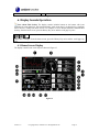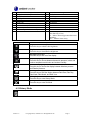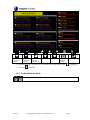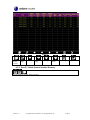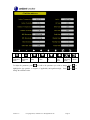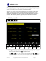
1
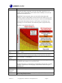
Ambient Weather WS-1001-WiFi OBSERVER Solar Powered Wireless WiFi Weather Station User Manual Table of Contents 1. 2. 3. 4. Introduction ..................................................................................................................................... 2 Warnings and Cautions ................................................................................................................... 2 Quick Start Guide............................................................................................................................ 2 Pre-Installation Checkout and Site Survey...................................................................................... 3 4.1 Pre Installation Checkout ....................................................................................................... 3 4.2 Site Survey ............................................................................................................................. 3 5. Getting Started ................................................................................................................................ 3 5.1 Parts List................................................................................................................................. 4 5.2 Recommend Tools .................................................................................................................. 5 5.3 Sensor Array Set Up ............................................................................................................... 6 5.3.1 Install Wind Vane ............................................................................................................... 7 5.3.2 Install Mounting Pole ......................................................................................................... 7 5.3.3 Install Batteries................................................................................................................... 9 5.3.4 Mount Weather Station ..................................................................................................... 11 5.3.5 Reset Button and Transmitter LED .................................................................................. 13 5.4 Indoor Thermo-Hygrometer-Barometer Transmitter ............................................................ 14 5.5 Best Practices for Wireless Communication ............................................................................... 15 5.6 Display Console ................................................................................................................... 15 6. Display Console Operation ........................................................................................................... 16 6.1 Home Screen Display ........................................................................................................... 16 6.2 History Mode........................................................................................................................ 17 6.2.1 Archive Memory Mode .................................................................................................... 18 6.2.2 Recall / Delete Annual Archive Memory ......................................................................... 19 6.2.3 Page Selection .................................................................................................................. 20 6.2.4 Historical Graphs ............................................................................................................. 21 6.3 Set Mode .............................................................................................................................. 23 6.3.1 Set Date and Time ............................................................................................................ 23 6.3.2 Set Time Format ............................................................................................................... 25 6.3.3 Temperature Units of Measure ......................................................................................... 25 6.3.4 Barometer Units of Measure ............................................................................................ 25 6.3.5 Wind Speed Units of Measure.......................................................................................... 25 6.3.6 Rainfall Units of Measure ................................................................................................ 25 6.3.7 Solar Radiation Units of Measure .................................................................................... 25 6.3.8 Rainfall Display Increments ............................................................................................. 25 6.3.9 Graph Time ...................................................................................................................... 26 6.3.10 Backlight Display......................................................................................................... 26 6.3.11 Longitude and Latitude ................................................................................................ 26 6.3.12 Barometer Display ....................................................................................................... 28 6.3.13 Weather Threshold ....................................................................................................... 29 6.3.14 Storm Threshold ........................................................................................................... 29 6.3.15 Current Weather ........................................................................................................... 29 6.3.16 Rainfall Season ............................................................................................................ 29 6.3.17 Archive Interval ........................................................................................................... 29 Version 1.0 ©Copyright 2014, Ambient LLC. All Rights Reserved. Page 1 6.3.18 Weather Server ............................................................................................................. 29 6.3.19 WiFi Scan ..................................................................................................................... 32 6.4 Alarm Mode ......................................................................................................................... 32 6.5 Calibration Mode.................................................................................................................. 33 6.6 Factory Default ..................................................................................................................... 37 6.6.1 Exporting Data File Format (Data Logging) .................................................................... 40 7. Glossary of Terms ......................................................................................................................... 41 8. Specifications ................................................................................................................................ 43 8.1 Wireless Specifications ........................................................................................................ 43 8.2 Measurement Specifications................................................................................................. 43 8.3 Power Consumption ............................................................................................................. 43 9. Maintenance .................................................................................................................................. 44 9.1 Advanced Rain Gauge Cleaning .......................................................................................... 44 10. Troubleshooting Guide ............................................................................................................. 46 11. Accessories ............................................................................................................................... 48 12. Liability Disclaimer .................................................................................................................. 48 13. FCC Statement.......................................................................................................................... 48 14. Warranty Information ............................................................................................................... 49 1. Introduction Thank you for your purchase of the Ambient Weather WS-1000-WiFi OBSERVER Solar Powered Wireless WiFi Weather Station. The following user guide provides step by step instructions for installation, operation and troubleshooting. To download the latest manual and additional troubleshooting tips, please visit: http://ambientweather.wikispaces.com/ws1001-wifi 2. Warnings and Cautions Warning: Any metal object may attract a lightning strike, including your weather station mounting pole. Never install the weather station in a storm. Warning: Installing your weather station in a high location may result in injury or death. Perform as much of the initial check out and operation on the ground and inside a building or home. Only install the weather station on a clear, dry day. 3. Quick Start Guide Although the manual is comprehensive, much of the information contained may be intuitive. In addition, the manual does not flow properly because the sections are organized by components. The following Quick Start Guide provides only the necessary steps to install, operate the weather station, and upload to the internet, along with references to the pertinent sections. Version 1.0 ©Copyright 2014, Ambient LLC. All Rights Reserved. Page 2 Step 1 2 3 6 4 5 7 8 9 Required Description Assemble and power up the sensor array Power up the indoor thermometer-hygrometer-barometer Power up the display console and synchronize with sensor array and thermo-hygrometer-barometer Mount the sensor array Set date and time on console Calibrate the relative pressure to sea-level conditions (local airport) on console Reset the rain to zero on console Optional Configure WiFi Register and upload to Weather Server Section 5.3.1 - 5.3.3 5.4 5.6 5.3.4 6.3.1 6.5 6.5 6.3.19 6.3.18 4. Pre-Installation Checkout and Site Survey 4.1 Pre Installation Checkout Before installing your weather station in the permanent location, we recommend operating the weather station for one week in a temporary location with easy access. This will allow you to check out all of the functions, insure proper operation, and familiarize you with the weather station and calibration procedures. This will also allow you to test the wireless range of the weather station. 4.2 Site Survey Perform a site survey before installing the weather station. Consider the following: 1. You must clean the rain gauge every few months and change the rechargeable batteries every 2-3 years. Provide easy access to the weather station. 2. Avoid radiant heat transfer from buildings and structures. In general, install the sensor array at least 5’ from any building, structure, ground, or roof top. 3. Avoid wind and rain obstructions. The rule of thumb is to install the sensor array at least four times the distance of the height of the tallest obstruction. For example, if the building is 20’ tall, and the mounting pole is 6’ tall, install 4 x (20 – 6)’ = 56’ away. 4. Wireless Range. The radio communication between receiver and transmitter in an open field can reach a distance of up to 330 feet, providing there are no interfering obstacles such as buildings, trees, vehicles, high voltage lines. Wireless signals will not penetrate metal buildings. Under most conditions, the maximum wireless range is 100’. 5. Radio interference such as PCs, radios or TV sets can, in the worst case, entirely cut off radio communication. Please take this into consideration when choosing console or mounting locations. Make sure your display console is at least five feet away from any electronic device to avoid interference. 6. Visit Ambient Weather Mounting Solutions for assistance and ideas for mounting your weather station: http://www.ambientweather.com/amwemoso.html 5. Getting Started The WS-1000-WiFi weather station consists of a display console (receiver), an all in one sensor array, Version 1.0 ©Copyright 2014, Ambient LLC. All Rights Reserved. Page 3 and wireless thermo-hygrometer-barometer. 5.1 Parts List QTY 1 Item Display Console Frame Dimensions 7.75 x 5.75 x 0.75” Image (LxWxH): LCD Dimensions (LxW): 6.25 x 3.5” 1 Thermo-hygrometer-barometer transmitter 1 Thermo-hygrometer-barometer mounting bracket plus 3 mounting screws 1 Sensor Array 1 Wind Vane Version 1.0 ©Copyright 2014, Ambient LLC. All Rights Reserved. Page 4 QTY 1 Item 5V DC Adaptor 2 Pole (straight and crimped) 2 Pole mounting U-bolt 4 Pole mounting clamps 4 Pole mounting U-bolt nuts 1 Allen wrench 1 User manual Image 5.2 Recommend Tools Precision screwdriver (for small Phillips screw on battery cover door) Adjustable wrench (for mounting pole) Compass or GPS (for wind direction calibration) Version 1.0 ©Copyright 2014, Ambient LLC. All Rights Reserved. Page 5 5.3 Sensor Array Set Up Figure 1 No 1 Description Wind Vane (measures wind direction) No 7 2 3 4 5 Wind Speed Sensor (measures wind speed) Solar collector Rechargeable battery compartment LED transmission indicator (turns on for 4 seconds on power up, flashes once per 16 seconds) Reset button 8 9 10 11 6 Version 1.0 Description Thermo-hygrometer Sensor temperature and humidity) UV Sensor Solar Radiation Sensor Rain Collector (self emptying) Bubble Level ©Copyright 2014, Ambient LLC. All Rights Reserved. Page 6 (measures 5.3.1 Install Wind Vane Reference Figure 2. (a) Locate and align the flat key on the wind vane shaft to the flat key on the wind vane and push the vane on to the shaft. (b) tighten the set screw with the hex wrench (included). (a) (b) Figure 2 5.3.2 Install Mounting Pole Reference Figure 3. Remove the mounting pole collar by rotating counter clockwise. Figure 3 Version 1.0 ©Copyright 2014, Ambient LLC. All Rights Reserved. Page 7 Reference Figure 4. Locate and align the groove on the sensor array and mounting pole. Figure 4 Version 1.0 ©Copyright 2014, Ambient LLC. All Rights Reserved. Page 8 Reference Figure 5. Turn the mounting pole collar to lock the pole into place by rotating clockwise. Figure 5 5.3.3 Install Batteries Reference Figure 6. Locate the battery door on the bottom of the sensor array. Turn the set screw counter clockwise to open the battery compartment. Insert the 3xAA rechargeable batteries (included). The LED indicator on the bottom of the sensor array will turn on for four seconds and normally flash once per 16 seconds (the transmission update period). Close the battery door and tighten the set screw. Version 1.0 ©Copyright 2014, Ambient LLC. All Rights Reserved. Page 9 Figure 6 Version 1.0 ©Copyright 2014, Ambient LLC. All Rights Reserved. Page 10 5.3.4 Mount Weather Station There are two methods for attaching your weather station: A. Option 1: Mounting Clamps. Fasten the mounting pole to your mounting pole or bracket (purchased separately) with the two U-bolts, mounting pole brackets and nuts, as shown in Figure 7. Tighten the mounting pole to your mounting pole with the U-Bolt assembly. Make sure your mounting pole is as far away from the temperature sensor as possible, as shown in Figure 7. Figure 7 B. Option 2: Swedged Pole Mount. Insert the swedged end of the included mounting pole into the open end of any standard mounting pole solution (1 3/8” diameter) available from Ambient Weather, as shown in Figure 8. For more information on mounting solutions, visit: http://www.ambientweather.com/amwemoso.html Version 1.0 ©Copyright 2014, Ambient LLC. All Rights Reserved. Page 11 Figure 8 1. Reference Figure 9. Locate the four wind vane compass rose indicators of N, E, S, W (representing North, East, South and West). Align the compass rose direction upon final installation with a compass or GPS. Figure 9 Version 1.0 ©Copyright 2014, Ambient LLC. All Rights Reserved. Page 12 2. Reference Figure 10. Make sure the sensor array is completely level upon final installation. Failure to do so will result in inaccurate rain gauge readings. Figure 10 5.3.5 Reset Button and Transmitter LED In the event the sensor array is not transmitting, reset the sensor array. With an open ended paperclip, press and hold the RESET BUTTON for three seconds to completely discharge the voltage. Take out the batteries and wait one minute, while covering the solar panel to drain the voltage. Put batteries back in and resynchronize with console by powering down and up the console with the sensor array about 10 feet away. Figure 11 Version 1.0 ©Copyright 2014, Ambient LLC. All Rights Reserved. Page 13 5.4 Indoor Thermo-Hygrometer-Barometer Transmitter The indoor thermometer, hygrometer and barometer measures and displays the indoor temperature, humidity and pressure and transmits this data to the display console. Figure 12 Note: Do not install the thermo-hygrometer-barometer transmitter outside. This will cause errors in the barometric pressure due to large variations in temperature (barometric pressure is temperature compensated for accuracy). Note that pressure readings made inside your home, business, or facility will correspond closely to the actual barometric pressure outside. Note: The thermo-hygrometer-transmitter transmits directly to the display console. For best results, place between 5 to 20 feet from the display console. Note: To avoid permanent damage, please take note of the battery polarity before inserting the batteries. Remove the battery door on the back of the sensor with a Philips screwdriver (there is only one screw, at the bottom of the unit). Insert two AAA batteries, as shown in Figure 13. Replace the battery door and set screw. Note that the temperature, humidity and barometric pressure will be displayed on the LCD display. Looking at the back of the unit from left to right, the polarity is (-) (+) for the top battery and (+) (-) for the bottom battery. Version 1.0 ©Copyright 2014, Ambient LLC. All Rights Reserved. Page 14 Figure 13 5.5 Best Practices for Wireless Communication Note: To insure proper communication, mount the remote sensor(s) upright on a vertical surface, such as a wall. Do not lay the sensor flat. Wireless communication is susceptible to interference, distance, walls and metal barriers. We recommend the following best practices for trouble free wireless communication. 1. Electro-Magnetic Interference (EMI). Keep the console several feet away from computer monitors and TVs. 2. Radio Frequency Interference (RFI). If you have other 433 MHz devices and communication is intermittent, try turning off these other devices for troubleshooting purposes. You may need to relocate the transmitters or receivers to avoid intermittent communication. 3. Line of Sight Rating. This device is rated at 300 feet line of sight (no interference, barriers or walls) but typically you will get 100 feet maximum under most real-world installations, which include passing through barriers or walls. 4. Metal Barriers. Radio frequency will not pass through metal barriers such as aluminum siding. If you have metal siding, align the remote and console through a window to get a clear line of sight. The following is a table of reception loss vs. the transmission medium. Each “wall” or obstruction decreases the transmission range by the factor shown below. Medium RF Signal Strength Reduction 5-15% 10-15% 10-40% 10-40% 40-80% 90-100% Glass (untreated) Plastics Wood Brick Concrete Metal 5.6 Display Console Connect the display console power jack to AC power with the power adapter (included), as shown in Figure 14. Place the sensor array and indoor thermo-hygrometer transmitter about 5 to 10 feet from the display console and wait several minutes for the remote sensors to synchronize with the display console. No Version 1.0 Description 1 Memory card slot for upgrades and backup data 2 Power jack ©Copyright 2014, Ambient LLC. All Rights Reserved. Page 15 3 Reset Figure 14 6. Display Console Operation Note: About This Section. The display console includes buttons at the bottom with icons signifying the menu functions. This manual includes “quick menu boxes” as shown below, signifying how to access a setting from home screen. For example, to access Recall and delete annual archive memory, from the home screen, press the History Key twice and the recall page key once: “Menu box” example. From the home screen, press the History Key twice and the recall page key once. 6.1 Home Screen Display The display console home screen layout is shown in Figure 15. Figure 15 Version 1.0 ©Copyright 2014, Ambient LLC. All Rights Reserved. Page 16 No 1 2 3 4 5 6 7 8 9 10 Description Graph (barometer, temperature or humidity) Wind Direction Wind Speed Wind Gust Wind Chill Internet Connectivity WiFi Connectivity Indoor Temperature & Humidity Outdoor Temperature & Humidity Dew Point Icon No 11 12 13 14 15 16 17 18 19 20 Description Heat Index Rainfall Date and Time Sunset Moon Phase Sunrise Barometer UV Solar Radiation Low Battery Indicators (only displayed when batteries are low) IN – Indoor Thermo-hygrometer-barometer transmitter OUT – Outdoor Sensor Array Description Brightness control key Press this key to enhance the brightness Brightness control key Press this key to decrease the brightness Backlight on/off key Press this key to turn on/off the display Graph display key Press this key to choose between barometric pressure, indoor and outdoor temperature and indoor and outdoor humidity Pressure display key Press this key to choose the display between Absolute pressure and Relative pressure. Rain key Press this key to Shift the display between Rain Rate, Rain Day, Rain Week, Rain Month, and Rain Year. History key Press this key to enter History Mode Set key Press this key to enter Set Mode 6.2 History Mode View and reset minimum and maximums. Version 1.0 ©Copyright 2014, Ambient LLC. All Rights Reserved. Page 17 Figure 16 Check parameter to clear Uncheck parameter to clear Clear selected parameter.(1) scroll up scroll down View archive memory return home (1) The popup message “Are you sure you want to clear the max/min?” Select “Yes” and to highlight to confirm. 6.2.1 Archive Memory Mode View archive memory for all parameters, based on the date and time. Version 1.0 ©Copyright 2014, Ambient LLC. All Rights Reserved. Page 18 Figure 17 Recall annual records Recall page scroll left scroll right scroll up scroll down View graphs return home 6.2.2 Recall / Delete Annual Archive Memory Recall and delete annual archive memory. Version 1.0 ©Copyright 2014, Ambient LLC. All Rights Reserved. Page 19 Figure 18 Delete annual record scroll left scroll right Recall annual record return to archive memory mode 6.2.3 Page Selection While viewing the annual archive memory, press the Version 1.0 key to view a specific page of memory. ©Copyright 2014, Ambient LLC. All Rights Reserved. Page 20 Figure 19 Increase page number Decrease page number Scroll digit to left scroll digit right Toggle OK or cancel, then press Toggle OK or cancel, then press to confirm to confirm 6.2.4 Historical Graphs Display historical graph data. Version 1.0 ©Copyright 2014, Ambient LLC. All Rights Reserved. Page 21 Figure 20 Zoom in Y-axis Version 1.0 Zoom out Y-axis scroll x-axis (time) left scroll x-axis (time) right Recall annual archivc data scroll parameter pages ©Copyright 2014, Ambient LLC. All Rights Reserved. Return to Max/Min Return home Page 22 6.3 Set Mode Enter the Setup Mode Figure 21 Select units of measure or scroll value up Select units of measure or scroll value down Select value Select value Scroll field up Scroll field down Enter sub-setup mode return to home 6.3.1 Set Date and Time Set the date and time. Set automatic time synchronization 1. Set Time. (hour:minute:second) Press to set the time. The hour field will turn red. Press Press or to select hour, minute or second. Press decrease the value. 2. Set Date. (month:day:year) Press or value. Version 1.0 to increase or to set the date. The month field will turn red. Press to select month, day or year. Press 3. Set Time Zone. Press or or to set the time zone. Press ©Copyright 2014, Ambient LLC. All Rights Reserved. to increase or decrease the to increase the time zone and Page 23 to decrease the time zone. With time zone highlighted, press to set Daylight Savings Time (DST). Press to toggle ON or OFF. Note: the DST should be always checked to automatically update the time when DST changes. 4. Set Time Server. The default time server is time.nist.gov. Press Press again to turn ON. Press highlight Update and to toggle ON or OFF. Press to set the time server. to immediately to to immediately update. Note: The time server will not work until the WiFi connection has been set up. Figure 22 scroll value up Version 1.0 scroll value down Select value Select value Scroll field up ©Copyright 2014, Ambient LLC. All Rights Reserved. Scroll field down return to Setup Page 24 6.3.2 Set Time Format x2 Press to change the time format between hour:minute:second hour:minute:second (AM h:mm:ss) and hour:minute:second AM (h:mm:ss AM). (h:mm:ss), AM 6.3.3 Temperature Units of Measure x3 Press to change the temperature units of measure between °F and °C. 6.3.4 Barometer Units of Measure x4 Press to change the temperature units of measure between inHg, mmHg and hpa. 6.3.5 Wind Speed Units of Measure x5 Press to change the wind speed units of measure between mph, bft (beufort scale), ft/s, m/s, km/h and knot. 6.3.6 Rainfall Units of Measure x6 Press to change the rainfall units of measure between in and mm. 6.3.7 Solar Radiation Units of Measure x7 Press to change the solar radiation units of measure between W/m^2, lux and fc. 6.3.8 Rainfall Display Increments x8 Press to change the rainfall display increments between Daily Rain, Weekly Rain, Monthly Rain, Yearly Rain, and Rain Rate. Version 1.0 ©Copyright 2014, Ambient LLC. All Rights Reserved. Page 25 6.3.9 Graph Time x9 Press to change the home screen graph display between 24, 48 and 72 hours (note: the graph will clear when the graph increment of measure is changed). The default is 72 hours. 6.3.10 Backlight Display x 10 Automatically turn on and off the backlight or adjust the brightness based on the time of day. Figure 23 adjust up or check adjust down or uncheck scroll left scroll right scroll up scroll down return home 6.3.11 Longitude and Latitude x 12 Set longitude and latitude for your location. This calculation is used for the sunrise and sunset calculation. 1. Latitude. Press to set the Northern or Southern Hemisphere. In the USA, the hemisphere setting is NORTH. To change to SOUTH, press the Press Version 1.0 key. to change your latitude. The longitude x 10 will turn red. Press ©Copyright 2014, Ambient LLC. All Rights Reserved. Page 26 or to increase or decrease the value. variables. 2. Longitude. Press Press or to change the remaining latitude to set the Western or Eastern Hemisphere. In the USA, the hemisphere setting is WEST. To change to EAST, press the Press key. to change your longitude. The longitude x 100 will turn red. Press to increase or decrease the value. variables. Press or or to change the remaining longitude Figure 24 To determine your longitude and latitude, we recommend the following website: www.bing.com/maps Reference Figure 25 below: 1. Enter your address and select the search button 2. The latitude (first number) and longitude (second number) are returned. In this example: Latitude = 33.2981181889772 Longitude = -111.960209459066 The table below defines the hemisphere based on the positive or negative sign: Position Latitude Longitude Version 1.0 Positive Northern Eastern Negative Southern Western ©Copyright 2014, Ambient LLC. All Rights Reserved. Page 27 3. In this example, the location entered into the display is as follows: Latitude = 33.30 North Longitude = 111.96 West after rounding to two significant digits. Record your longitude and latitude here for future reference: Longitude: Latitude: Figure 25 6.3.12 Barometer Display x 11 Press to change the barometer display between REL (relative pressure) and ABS (absolute pressure). Note: The weather station console displays two different pressures: absolute (measured) and relative (corrected to sea-level). To compare pressure conditions from one location to another, meteorologists correct pressure to sea-level conditions. Because the air pressure decreases as you rise in altitude, the sea-level corrected pressure (the pressure your location would be at if located at sea-level) is generally higher than your measured pressure. Thus, your absolute pressure may read 28.62 inHg (969 mb) at an altitude of 1000 feet (305 m), but the relative pressure is 30.00 inHg (1016 mb). Version 1.0 ©Copyright 2014, Ambient LLC. All Rights Reserved. Page 28 The standard sea-level pressure is 29.92 in Hg (1013 mb). This is the average sea-level pressure around the world. Relative pressure measurements greater than 29.92 inHg (1013 mb) are considered high pressure and relative pressure measurements less than 29.92 inHg are considered low pressure. 6.3.13 Weather Threshold Currently not used. 6.3.14 Storm Threshold Currently not used. 6.3.15 Current Weather Currently not used. 6.3.16 Rainfall Season x 13 Press to change the beginning of the rainfall yearly season month. The default is January. 6.3.17 Archive Interval x 14 Changes the archive interval for historical data and graphing. Press field. Press Press to highlight the 10 x minute field. Press to highlight the minute field. Press to change the 100 x minute to change the 10 x minute field. to change the minute field. 6.3.18 Weather Server x 15 The console is configured to send real-time data to Wunderground.com so there is no need to adjust the Server, Server type, and upload type. Enter the Station ID and Password from Wunderground.com. Enter your Station ID and password obtained from Wunderground.com Version 1.0 ©Copyright 2014, Ambient LLC. All Rights Reserved. Page 29 Figure 26 scroll value up scroll down value 1. Set Station ID. Press Wunderground.com. Press Scroll field up Wunderground.com. Press return to Setup to highlight the Station ID. Enter your station ID obtained from to display the keyboard. Press to scroll to the character and press Wunderground.com setup page. 2. Set Password. Press Scroll field down to select the character. Press to return to the to highlight the Password. Enter your password obtained from to display the keyboard. Press to scroll to the character and press Wunderground.com setup page. to select the character. Press to return to the Note: How to create a Wunderground.com account and station ID. 1. Join the Wunderground.com Community. Visit: https://www.wunderground.com/members/signup.asp and sign up with Wunderground.com. Version 1.0 ©Copyright 2014, Ambient LLC. All Rights Reserved. Page 30 2. Join the Personal Weather Station (PWS) network. Visit: http://www.wunderground.com/weatherstation/about.asp and Get Started! to add your weather station and you will receive a Station ID. Enter the Station ID obtained and password you entered in the console’s Weather Server page. Note: If Wunderground.com is not updating, make sure the Station ID and Password are correct. The Station ID is all capital letters, and the password is case sensitive. The most common issue is substituting an O for 0 in the Station ID. Example, You live in Phoenix, AZ and you are station number 11: KAZPHOEN11, not KAZPH0EN11 K = USA station designation AZ = Arizona PHOEN = Phoenix 11= station 11 in Phoenix, AZ Version 1.0 ©Copyright 2014, Ambient LLC. All Rights Reserved. Page 31 6.3.19 WiFi Scan x 16 Press to select your wireless network. Press to enter the password. Press to scroll to the character and press to select the character. Press to return to the WiFi Network setup page. Leave the password blank of the WiFi network is not encrypted. Note: The WiFi signal strength icon is displayed on the home page . If wireless connectivity is successful and you are reporting to Wunderground.com, the WiFi icon the wind chill display on the home page. will be displayed under Figure 27 Select value Select value Scroll field up Scroll field down Select return to Setup 6.4 Alarm Mode Enter the Alarm Mode The upper alarm is displayed on the right and the lower alarm is displayed on the left. If the measured value is greater than the maximum alarm setting, the alarm will sound. If the measured value is less than the minimum alarm setting, the alarm will sound. Version 1.0 ©Copyright 2014, Ambient LLC. All Rights Reserved. Page 32 To adjust the alarm, press to scroll to the alarm setting you wish to change. Press highlight the sign (positive vs. negative) and significant digit. Press To set the alarm,, press ON or OFF. to highlight the alarm symbol to to change the value. and press to toggle the alarm When a weather alarm condition has been triggered, the alarm will sound for 120 seconds and the corresponding icon will flash until the weather condition is no longer present. Press any key to mute the alarm. You can also set a time of day alarm using the same method. Figure 28 Increase alarm limit values Decrease alarm limit values Select value Select value Scroll field up Scroll field down Enter sub-setup mode 6.5 Calibration Mode Enter the Calibration (Correct) Mode Version 1.0 ©Copyright 2014, Ambient LLC. All Rights Reserved. Page 33 return to home Figure 29 Increase calibrated value Decrease calibrated value Select value To adjust the parameter, press Select value Scroll field up Scroll field down Enter sub-setup mode to scroll to the parameter you wish to change. Press highlight the sign (positive vs. negative, if applicable) and significant digit. Press change the calibrated value. Version 1.0 return to home ©Copyright 2014, Ambient LLC. All Rights Reserved. Page 34 or to to Parameter Temperature Type of Calibration Offset Default Typical Calibration Source Current Value Red Spirit or Mercury Thermometer (1) Humidity Offset Current Value Sling Psychrometer (2) ABS Offset Current Value Calibrated laboratory grade Barometer barometer REL Barometer Offset Current Value Local airport (3) Wind Direction Offset Current Value GPS, Compass (4) Solar Radiation Gain 1.00 Calibrated laboratory grade solar radiation sensor 1 w/m2 Gain 126.7 lux Solar radiation conversion from lux to w/m2 for wavelength correction (5) Wind Gain 1.00 Calibrated laboratory grade wind meter (6) Rain Gain 1.00 Sight glass rain gauge with an aperture of at least 4” (7) Daily Rain Offset Current Value Apply an offset if the weather station was not operating for the entire day. Weekly Rain Offset Current Value Apply an offset if the weather station was not operating for the entire week. Monthly Rain Offset Current Value Apply an offset if the weather station was not operating for the entire month. Yearly Rain Offset Current Value Apply an offset if the weather station was not operating for the entire year. (1) Temperature errors can occur when a sensor is placed too close to a heat source (such as a building structure, the ground or trees). To calibrate temperature, we recommend a mercury or red spirit (fluid) thermometer. Bi-metal (dial) and digital thermometers (from other weather stations) are not a good source and have their own margin of error. Using a local weather station in your area is also a poor source due to changes in location, timing (airport weather stations are only updated once per hour) and possible calibration errors (many official weather stations are not properly installed and calibrated). Place the sensor in a shaded, controlled environment next to the fluid thermometer, and allow the sensor to stabilize for 48 hours. Compare this temperature to the fluid thermometer and adjust the console to match the fluid thermometer. (2) Humidity is a difficult parameter to measure electronically and drifts over time due to contamination. In addition, location has an adverse affect on humidity readings (installation over dirt vs. lawn for example). Official stations recalibrate or replace humidity sensors on a yearly basis. Due to manufacturing tolerances, the humidity is accurate to ± 5%. To improve this accuracy, the indoor and outdoor humidity can be calibrated using an accurate source, such as a sling Version 1.0 ©Copyright 2014, Ambient LLC. All Rights Reserved. Page 35 psychrometer. (3) The display console displays two different pressures: absolute (measured) and relative (corrected to sea-level). To compare pressure conditions from one location to another, meteorologists correct pressure to sea-level conditions. Because the air pressure decreases as you rise in altitude, the sea-level corrected pressure (the pressure your location would be at if located at sea-level) is generally higher than your measured pressure. Thus, your absolute pressure may read 28.62 inHg (969 mb) at an altitude of 1000 feet (305 m), but the relative pressure is 30.00 inHg (1016 mb). The standard sea-level pressure is 29.92 in Hg (1013 mb). This is the average sea-level pressure around the world. Relative pressure measurements greater than 29.92 inHg (1013 mb) are considered high pressure and relative pressure measurements less than 29.92 inHg are considered low pressure. To determine the relative pressure for your location, locate an official reporting station near you (the internet is the best source for real time barometer conditions, such as Weather.com or Wunderground.com), and set your weather station to match the official reporting station. (4) Only use this if you improperly installed the weather station sensor array, and did not point the direction reference to true north. (5) The default conversion factor based on the wavelength for bright sunlight is 126.7 lux / w/m2 . This variable can be adjusted by photovoltaic experts based on the light wavelength of interest, but for most weather station owners, is accurate for typical applications, such as calculating evapotransporation and solar panel efficiency. (6) Wind speed is the most sensitive to installation constraints. The rule of thumb for properly installing a wind speed sensor is 4 x the distance of the tallest obstruction. For example, if your house is 20’ tall and you mount the sensor on a 5’ pole: Distance = 4 x (20 – 5)’ = 60’. Many installations are not perfect and installing the weather station on a roof can be difficult. Thus, you can calibrate for this error with a wind speed multiplier. In addition to the installation challenges, wind cup bearings (moving parts) wear over time. Without a calibrated source, wind speed can be difficult to measure. We recommend using a calibrated wind meter (available from Ambient Weather) and a constant speed, high speed fan. (7) The rain collector is calibrated at the factory based on the funnel diameter. The bucket tips every 0.01” of rain (referred to as resolution). The accumulated rainfall can be compared to a sight glass rain gauge with an aperture of at least 4”. The following is a link to an accurate sight glass rain gauge: http://www.ambientweather.com/stprraga.html Make sure you periodically clean the rain gauge funnel. Version 1.0 ©Copyright 2014, Ambient LLC. All Rights Reserved. Page 36 Note: The purpose of calibration is to fine tune or correct for any sensor error associated with the devices margin of error. Errors can occur due to electronic variation (example, the temperature sensor is a resistive thermal device or RTD, the humidity sensor is a capacitance device), mechanical variation, or degradation (wearing of moving parts, contamination of sensors). Calibration is only useful if you have a known calibrated source you can compare it against, and is optional. This section discusses practices, procedures and sources for sensor calibration to reduce manufacturing and degradation errors. Do not compare your readings obtained from sources such as the internet, radio, television or newspapers. The purpose of your weather station is to measure conditions of your surroundings, which vary significantly from location to location. 6.6 Factory Default Enter the Factory Default Mode Figure 30 Select Setting Select Setting Scroll left Scroll right Scroll field up Scroll field down Enter sub-setup mode return to home 1. Re-register Transmitter Indoor. Re-synchronizes the wireless signal from the indoor thermo-hygrometer-barometer. Press to highlight this field. Press or key to select re-register indoor transmitter. Press or key to popup the Message Box ”Are you sure you want to register the new indoor transmitter?” Version 1.0 ©Copyright 2014, Ambient LLC. All Rights Reserved. Page 37 Press or to select Yes or No. Press the key or key to confirm the selection. 2. Re-register Transmitter Outdoor. Re-synchronizes the wireless signal from the outdoor sensor array. Press to highlight this field. Press or key to select re-register indoor transmitter. Press or key to popup the Message Box ”Are you sure you want to register the new outdoor transmitter?” Press or to select Yes or No. Press the key or key to confirm the selection. 3. Clear History. Clears all of the historical data in archive memory. Press field. Press or key to select re-register indoor transmitter. Press popup the Message Box ”Are you sure you want to clear history?” Press Yes or No. Press the key or key to confirm the selection. to highlight this or or key to to select 4. Clear Max/Min. Clears all of the minimum and maximum values in stored memory. to highlight this field. Press or key to select re-register indoor transmitter. Press or popup the Message Box ”Are you sure you want to clear the max/min?” Press select Yes or No. Press the key or key to confirm the selection. or Press key to to 5. Reset to Factory Default. Clears all stored memory, calibrations and other variables to factory default. Press to highlight this field. Press or key to select re-register indoor transmitter. Press or popup the Message Box ”Are you sure you want to reset to factory default?” Press to select Yes or No. Press the key or key to confirm the selection. key to or 6. Backup data. Backup data to micro SD / TF card (see the Accessories section of this manual for more information on micro SD / TF cards). Insert the micro SD / TF Card into the slot, as shown in Figure 14. Press to highlight this field. Press to enter the backup mode. Press or to select the history year file. Press to confirm the selection, and the year field will turn from green to purple. Press backup. to start the backup, press key again to cancel the The data is stored in comma separated value (csv) file format, which can be opened in Microsoft Excel. The TF card can be read by a computer with an SD card adaptor. Version 1.0 ©Copyright 2014, Ambient LLC. All Rights Reserved. Page 38 Figure 31 Select Setting Select Setting Select year history file Select year history file Scroll field up Scroll field down Start or stop backup Figure 32 Version 1.0 ©Copyright 2014, Ambient LLC. All Rights Reserved. Page 39 return to Factory menu 6.6.1 Exporting Data File Format (Data Logging) The format of the data is csv (comma separated value) and can be opened in a spreadsheet program such as Microsoft Excel for advanced data analysis, with the following headers: Column 1 2 3 4 5 6 7 8 9 10 11 12 13 14 15 16 17 18 19 20 21 22 Parameter No (data point number) Time Indoor Temperature (°F) Indoor Humidity (%) Outdoor Temperature (°F) Outdoor Humidity (%) Dew Point (°F) Wind Chill (°F) Wind (mph) Gust (mph) Wind Direction (°) ABS Barometer (inHg) REL Barometer (inHg) Rain Rate (in/h) Daily Rain (in) Weekly Rain (in) Monthly Rain (in) Yearly Rain (in) Solar Rad. (lux) Heat Index (°F) UV (uW/cm^2) UV Index 7. Language. Supports English, Chinese,. Danish, Dutch, French, German, Italian and Spanish. Press changes. to highlight this field. Press to select the language and to accept the 8. About. Provides detailed information for troubleshooting purposes. Version 1.0 ©Copyright 2014, Ambient LLC. All Rights Reserved. Page 40 Figure 33 7. Glossary of Terms Term Absolute Barometric Pressure Accuracy Barometer Calibration Dew Point Heat Index Version 1.0 Definition Absolute pressure is the measured atmospheric pressure and is a function of altitude, and to a lesser extent, changes in weather conditions. Absolute pressure is not corrected to sea-level conditions. Refer to Relative Barometric Pressure. Accuracy is defined as the ability of a measurement to match the actual value of the quantity being measured. A barometer is an instrument used to measure atmospheric pressure. Calibration is a comparison between measurements – one of known magnitude or correctness of one device (standard) and another measurement made in as similar a way as possible with a second device (instrument). The dew point is the temperature at which a given parcel of humid air must be cooled, at constant barometric pressure, for water vapor to condense into water. The condensed water is called dew. The dew point is a saturation temperature. The dew point is associated with relative humidity. A high relative humidity indicates that the dew point is closer to the current air temperature. Relative humidity of 100% indicates the dew point is equal to the current temperature and the air is maximally saturated with water. When the dew point remains constant and temperature increases, relative humidity will decrease. The Heat Index, sometimes referred to as the apparent temperature, is a measure of how hot it really feels when relative humidity is factored with the actual air temperature. ©Copyright 2014, Ambient LLC. All Rights Reserved. Page 41 Term Definition To find the Heat Index temperature, look at the Heat Index chart below. As an example, if the air temperature is 96°F and the relative humidity is 65%, the heat index (how hot it feels) is 121°F. IMPORTANT: Since heat index values were devised for shady, light wind conditions, exposure to full sunshine can increase heat index values by up to 15°F. Also, strong winds, particularly with very hot, dry air, can be extremely hazardous. The Heat Index Chart shaded zone above 105°F shows a level that may cause increasingly severe heat disorders with continued exposure or physical activity. Heat Index is not calculated below 80°F. HectoPascals (hPa) Hygrometer Inches of Mercury (inHg) Rain Gauge Range Relative Barometric Pressure Resolution Version 1.0 Pressure units in SI (international system) units of measurement. Same as millibars (1 hPa = 1 mbar) A hygrometer is a device that measures relative humidity. Relative humidity is a term used to describe the amount or percentage of water vapor that exists in air. Pressure in Imperial units of measure. 1 inch of mercury = 33.86 millibars A rain gauge is a device that measures liquid precipitation (rain), as opposed to solid precipitation (snow gauge) over a set period of time. All digital rain gauges are self emptying or self dumping (also referred to as tipping rain gauge). The precision of the rain gauge is based on the volume of rain per emptying cycle. Range is defined as the amount or extent a value can be measured. Measured barometric pressure relative to your location or ambient conditions. Resolution is defined as the number of significant digits (decimal places) to which a value is being reliably measured. ©Copyright 2014, Ambient LLC. All Rights Reserved. Page 42 Term Solar Radiation Definition A solar radiation sensor measures solar energy from the sun. Solar radiation is radiant energy emitted by the sun from a nuclear fusion reaction that creates electromagnetic energy. The spectrum of solar radiation is close to that of a black body with a temperature of about 5800 K. About half of the radiation is in the visible short-wave part of the electromagnetic spectrum. The other half is mostly in the near-infrared part, with some in the ultraviolet part of the spectrum. Thermometer Wind Vane A thermometer is a device that measures temperature. Most digital thermometers are resistive thermal devices (RTD). RTDs predict change in temperature as a function of electrical resistance. A wind vane is a device that measures the direction of the wind. The wind vane is usually combined with the anemometer. Wind direction is the direction from which the wind is blowing. 8. Specifications 8.1 Wireless Specifications Line of sight wireless transmission (in open air): 330 feet, 100 feet under most conditions Update Rate: Outdoor Sensor: 16 seconds, Indoor Sensor: 64 seconds Frequency: 915 MHz 8.2 Measurement Specifications The following table provides the specifications for the measured parameters. Measurement Indoor Temperature Outdoor Temperature Indoor Humidity Outdoor Humidity Barometric Pressure Range 32 to 140 °F -40 to 149 °F sensor -23 to 140 °F rechargeable battery range (alkaline) 1 to 99% 1 to 99% 8.85 to 32.50 inHg Light Rain Wind Direction Wind Speed 0 to 400,000 Lux 0 to 394 in. 0 - 360 º 0 to 100 mph (operational) Accuracy ± 2 °F ± 2 °F Resolution 0.1 °F 0.1 °F ± 5% ± 5% ± 0.08 inHg (within range of 27.13 to 32.50 inHg) ± 15% ± 10% 1º ± 2.2 mph or 10% (whichever is greater) 1% 1% 0.01 inHg 1 Lux 0.01 in 1º 0.1 mph 8.3 Power Consumption Base station : 5V DC Adaptor (included), Power Consumption: 7.5 Watts Indoor Thermo-hygrometer-barometer sensor : 2xAAA batteries (not included) Outdoor sensor array: 3xAA alkaline rechargeable batteries (included) Version 1.0 ©Copyright 2014, Ambient LLC. All Rights Reserved. Page 43 9. Maintenance 1. Clean the rain gauge once every 3 months as follows. Reference Figure 34. Step 1: Make a note of the current rain totals by referencing the calibration screen (reference Section 6.5). You will need to re-enter these values after the calibration procedure it complete. Step 2: Pour water into the rain collector to moisturize the dirt inside rain bucket. Step 3: Use an approximately 3 inch (80 mm) long cotton swab, and push the cotton tip through the rain collector hole until is reaches the self emptying mechanism, and press until the mechanism no longer rotates. Step 4: Rotate the cotton swab back and forth, removing dirt from the tipping mechanism and rain collector hole. Step 5: Remove the cotton swab and flush with water to remove any remaining dirt. Step 6: Re-enter the rain totals recorded in Step 1. Figure 34 2. Clean the solar radiation sensor every 3 months with water and towel. 3. Replace rechargeable batteries every 2 to 3 years. 9.1 Advanced Rain Gauge Cleaning If the rain gauge stops updating, it is possible for spiders and other insects to nest inside the sensor array housing and interfere with the rain gauge mechanism. 1. Remove the six screws on the bottom of the sensor array, as shown in Figure 35. 2. CAREFULLY separate the top housing from the bottom housing. They cannot be completely separated due to wires. DO NOT STRESS THE WIRES. Open the sensor housing slightly, like a clam shell. 3. Clean any debris and spider webs, as shown in Figure 36. Version 1.0 ©Copyright 2014, Ambient LLC. All Rights Reserved. Page 44 Figure 35 Figure 36 Version 1.0 ©Copyright 2014, Ambient LLC. All Rights Reserved. Page 45 10. Troubleshooting Guide If your question is not answered here, you can contact us as follows: 1. Email Support: [email protected] 2. Live Chat Support: www.ambientweather.com/chat.html (M-F 8am to 4pm Arizona Time) 3. Technical Support: 480-346-3398 (M-F 8am to 4pm Arizona Time) Problem Wireless remote (thermo-hygrometer) not reporting in to console. Solution The maximum line of sight communication range is about 300’. Move the sensor assembly closer to the display console. There are dashes on the display console. Install a fresh set of batteries in the remote sensor(s). Resynchronize the remote sensor(s). Reference Section 6.6. Make sure the remote sensors are not transmitting through solid metal (acts as an RF shield), or earth barrier (down a hill). Radio Frequency (RF) Sensors cannot transmit through metal barriers (example, aluminum siding) or multiple, thick walls. Outdoor sensor array does not communicate to the display console. Move the display console around electrical noise generating devices, such as computers, TVs and other wireless transmitters or receivers. The sensor array may have initiated properly and the data is registered by the console as invalid, and the console must be reset. The reset button is next to the LED, near the mounting point on the sensor array, as shown in Figure 11. With an open ended paperclip, press the reset button for 3 seconds to completely discharge the voltage. Take out the batteries and wait one minute, while covering the solar panel to drain the voltage. Put batteries back in and resync with console by powering down and up the console with the sensor array about 10 feet away. Bring the sensor array inside the house (you can disconnect it from the rest of the sensors). The LED next to the battery compartment will flash every 16 seconds. If the LED is not flashing every 16 seconds… Replace the batteries in the outside sensor array. Non-rechargeable batteries are OK for testing purposes. If the batteries were recently replaced, check the polarity. If the sensor is flashing every 48 seconds, proceed to the next step. There may be a temporary loss of communication due to reception loss related to interference or other location factors, or the batteries may have been changed in the sensor array and the console has not been reset. The solution may be as simple as powering down and up the console. Version 1.0 ©Copyright 2014, Ambient LLC. All Rights Reserved. Page 46 Problem Solution Replace the batteries in the outside sensor array. Non-rechargeable batteries are OK for testing purposes. Temperature sensor reads too high in the day time. Absolute pressure does not agree with official reporting station Rain gauge reports rain when it is not raining Data not reporting to Wunderground.com With the sensor array and console 10 feet away from each other, remove AC power from the display console and wait 10 seconds. Re-connect power. Make certain that the sensor array is not too close to heat generating sources or strictures, such as buildings, pavement, walls or air conditioning units. Use the calibration feature to offset installation issues related to radiant heat sources. Reference 6.5. You may be viewing the relative pressure, not the absolute pressure. Select the absolute pressure. Make sure you properly calibrate the sensor to an official local weather station. Reference Section 6.5 for details. An unstable mounting solution (sway in the mounting pole) may result in the tipping bucket incorrectly incrementing rainfall. Make sure you have a stable, level mounting solution. 1. Confirm your password is correct. It is the password you registered on Wunderground.com. Your Wunderground.com password cannot begin with a non-alphanumeric character (a limitation of Wundeground.com, not the station). Example, $oewkrf is not a valid password, but oewkrf$ is valid. 2. Confirm your station ID is correct. The station ID is all caps, and the most common issue is substituting an O for a 0 (or visa versa). Example, KAZPHOEN11, not KAZPH0EN11 3. Make sure the date and time is correct on the console. If incorrect, you may be reporting old data, not real time data. 4. Make sure your time zone is set properly. If incorrect, you may be reporting old data, not real time data. 5. Check your router firewall settings. The console sends data via Port 80. No WiFi connection 1. Check for WiFi signal strength symbol on the display . If wireless connectivity is successful and reporting to Wunderground.com, the WiFi icon will be displayed under the wind chill display on the home page. 2. Make sure your modem WiFi settings are correct (network name, password and security settings). Heat Index is not showing on the display Sunrise and sunset is incorrect Version 1.0 The heat index is not displayed for values less than 80 °F. Make certain your time zone, longitude and latitude are set properly. ©Copyright 2014, Ambient LLC. All Rights Reserved. Page 47 11. Accessories The following software and hardware accessories are available for this weather station at www.AmbientWeather.com . Accessory microSDHC Class 4 Flash Memory Card SDC4/8GB Description MicroSDHC for data backup and advanced data analysis. Ambient Weather Mounting Solutions Ambient Weather provides the most comprehensive mounting solutions for weather stations, including tripods, pole extensions, pole mounting kits, guy wires, ground stakes and more. Ambient Weather WS-1000-BATT 3 x AA Rechargeable Batteries for WS-1000-WiFi Outdoor Sensor Array (replacement). Ambient Weather WS-1000-BATT 3 x AA Rechargeable Batteries for WS-1000-WiFi Outdoor Sensor Array 12. Liability Disclaimer Please help in the preservation of the environment and return used batteries to an authorized depot. The electrical and electronic wastes contain hazardous substances. Disposal of electronic waste in wild country and/or in unauthorized grounds strongly damages the environment. Reading the “User manual” is highly recommended. The manufacturer and supplier cannot accept any responsibility for any incorrect readings and any consequences that occur should an inaccurate reading take place. This product is designed for use in the home only as indication of weather conditions. This product is not to be used for medical purposes or for public safety information. The specifications of this product may change without prior notice. This product is not a toy. Keep out of the reach of children. No part of this manual may be reproduced without written authorization of the manufacturer. Ambient, LLC WILL NOT ASSUME LIABILITY FOR INCIDENTAL, CONSEQUENTIAL, PUNITIVE, OR OTHER SIMILAR DAMAGES ASSOCIATED WITH THE OPERATION OR MALFUNCTION OF THIS PRODUCT. 13. FCC Statement Statement according to FCC part 15.19: This device complies with part 15 of the FCC rules. Operation is subject to the following two conditions: 1. This device may not cause harmful interference. 2. This device must accept any interference received, including interference that may cause undesired operation. Statement according to FCC part 15.21: Version 1.0 ©Copyright 2014, Ambient LLC. All Rights Reserved. Page 48 Modifications not expressly approved by this company could void the user's authority to operate the equipment. Statement according to FCC part 15.105: NOTE: This equipment has been tested and found to comply with the limits for a Class B digital device, pursuant to Part 15 of the FCC Rules. These limits are designed to provide reasonable protection against harmful interference in a residential installation. This equipment generates, uses and can radiate radio frequency energy and, if not installed and used in accordance with the instructions, may cause harmful interference to radio communications. However, there is no guarantee that interference will not occur in a particular installation. If this equipment does cause harmful interference to radio or television reception, which can be determined by turning the equipment off and on, the user is encouraged to try to correct the interference by one or more of the following measures: • Reorient or relocate the receiving antenna. • Increase the separation between the equipment and receiver. • Connect the equipment into an outlet on a circuit different from that to which the receiver is connected. • Consult the dealer or an experienced radio/TV technician for help. 14. Warranty Information Ambient, LLC provides a 1-year limited warranty on this product against manufacturing defects in materials and workmanship. This limited warranty begins on the original date of purchase, is valid only on products purchased and only to the original purchaser of this product. To receive warranty service, the purchaser must contact Ambient, LLC for problem determination and service procedures. Warranty service can only be performed by a Ambient, LLC. The original dated bill of sale must be presented upon request as proof of purchase to Ambient, LLC. Your Ambient, LLC warranty covers all defects in material and workmanship with the following specified exceptions: (1) damage caused by accident, unreasonable use or neglect (lack of reasonable and necessary maintenance); (3) damage resulting from failure to follow instructions contained in your owner’s manual; (4) damage resulting from the performance of repairs or alterations by someone other than an authorized Ambient, LLC authorized service center; (5) units used for other than personal use (6) applications and uses that this product was not intended (7) the products inability to receive a signal due to any source of interference or metal obstructions and (8) extreme acts of nature, such as lightning strikes or floods. This warranty covers only actual defects within the product itself, and does not cover the cost of installation or removal from a fixed installation, normal set-up or adjustments, claims based on misrepresentation by the seller or performance variations resulting from installation-related circumstances. Version 1.0 ©Copyright 2014, Ambient LLC. All Rights Reserved. Page 49