1
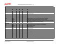
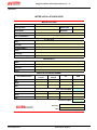
Design Guidelines & Procedures Version 18 © 20.00 Electrical Services The requirements of this Section are generally Mandatory (Refer to Section 1.00) 20.01 General Requirements This section outlines the University's minimum requirements for electrical services. The layout of luminaires and power outlets should allow flexibility such that spaces can be subdivided into separate areas. Where island rooms exist, these shall be conduited to allow for the installation of power and communication outlets from the relevant sub-board or Telecommunication Equipment Room (TER) where these are not installed in the first instance. 20.02 Lighting 20.02.01 Performance Guidelines All internal and external lighting shall be designed to enhance safe movement, personal safety and security (CPTED), refer to Section 2.00 Planning & Design Controls. The following lighting categories, in accordance with AS 1158.3.1 shall apply to the following nominated external areas; Bus stops Areas adjacent to entry/exit (5m radius) General grounds used for night activity General grounds adjacent to areas used for night activity Entrapment spots P6 P10 P7 P8 P10 Internal areas shall be designed in accordance with AS 1680 and shall also incorporate the requirements of AS 1428. Lighting levels for each area shall be nominated by the Consultant or Contractor and submitted for approval as part of Schematic Design. Over illumination is discouraged. Particular areas nominated for specialised requirements will be identified by the user in the SDFs and the appropriate lighting quality and levels recommended. 20.02.02 Design Requirements Luminaires – All luminaires shall be manufactured from Australian made components where possible and be approved by the Electricity Authority. All luminaires shall be supplied complete with lamps and fused terminal blocks. Spring loaded ‘tombstone’ lamp holders shall not be used. Single lamp luminaires generally shall be installed, however dual lamp luminaires may be used where high ceilings occur or high lighting levels are required. Fluorescent luminaires shall be of the high efficiency type incorporating high frequency warm/soft start ‘Osram’, ‘Tridonic Atco’ or approved equal electronic ballasts, with a suitable controller as outlined in Clause 20.03 of this Section. All luminaires shall be adequately ventilated. Temperature rise in the fittings should be restricted o to 50 C above ambient. Diffusers shall be integral to the luminaire and easily removable. All components shall be easily accessible, with the luminaire in-situ. Fittings which have to be dismantled in order to replace diffusers, lamps or tubes shall not be used. Diffusers to T8 single lamp luminaires shall be; K12 diffuser for common areas K19 diffusers for offices, computer rooms and seminar rooms Electrical Services Section 20.00 / Page 1 Design Guidelines & Procedures Version 18 © Installation of luminaires with a T5 lamp shall only occur with the express agreement of the Superintendent. Diffusers to T5 lamped luminaires shall be selected to suit the glare control requirements of the area while achieving a light output ratio (LOR) > 75%. The length and type of luminaire shall suit the ceiling module and/or location of the installation. Where existing fluorescent luminaires are to be reused, or approval for non-electronic ballasts has been given, the luminaires shall incorporate starters of the non-flickering warm/soft start electronic type, power factor corrected and be of the switch start type complete with fuse terminal blocks and low loss ballasts. Spring loaded tombstone lamp holders shall not be used. Luminaire design and layout should satisfy the intensity, glare and uniformity requirements for open offices with sufficient flexibility to enable partitioning of individual perimeter or island offices. For internal areas preference shall be given to 36w T8 lamps. The use of compact fluorescent lamps shall be limited and only with the express approval of the Superintendent. Generally, the number of different lamp source types shall be kept to a minimum. Fluorescent tube lamps shall be ‘Osram Lumilux Plus Eco’ or ‘Phillips Alto 840’ T8 cool white o (4000 K) or equivalent in all areas unless stated otherwise in the Space Description Forms to suit specific functions. Lamp selection shall be limited to the types currently used within the University as per the following Table. Table 1: Existing General Lamps Wattage 36 13,18,26 Metal Halide 70, 150, 250 High Pressure Sodium Base Type Fluorescent Lamps T8 Compact Fluorescent Lamps G24d-1, Dulux D, D/E, S, S/E G24q-1, G24d-2, or equal G24q-2, G24d-3, G24q-3 Discharge lamps RX7s, G12, E27 HCL-T DE, HCL-TS, HCL E/P or equal E40, E27 Eye Lighting or equal o K 4000 4000 4000 or more External lighting of buildings shall be discussed with the Superintendent. Roads and paths associated with a particular building shall be illuminated as part of that building project. Where paths run adjacent to, through or beneath buildings, the luminaire shall be mounted on the external wall of the building. White light (using metal halide fittings) shall be employed. Road and pathway lighting, which is apart from a building and which requires separate illumination, shall be achieved using pole-mounted luminaires to match existing on that campus, as approved by the Superintendent. Lighting bollards are generally unacceptable. All other external lighting, other than for sports fields, shall be High Pressure Sodium. All sports field, street and path lighting poles shall have terminals and fuses located in the base. Lighting poles shall be fitted with base plates and mounted on concrete pads or piers with cast-in holding down bolts complete with levelling nuts and washers. After erection, HD bolts shall be trimmed and capped to a maximum of 10mm above the lock nut. Poles with bases buried in footings are unacceptable. All external luminaires shall possess a suitable International Protection (IP) rating, to AS 1939, for the location of the luminaire. As a minimum the IP rating shall be such that the luminaire prevents the ingress of insects. Carpark and street lighting luminaires shall be ‘GEC Optispan’ on 9 metre high poles, or an approved equal to match existing. Pathway lighting luminaires shall be Bega 8821/8881 (Gold Coast campus), Bega 8889 (Nathan campus) or approved equal to match existing, mounted on 5 metre high poles. External lighting shall be on separate circuits. Where false ceilings exist, luminaires shall be connected to the wiring loom by means of a threepin plug and 1500mm of flexible lead. Lighting loom sockets in ceiling spaces shall be circuit numbered using the Sub Board No. and Circuit Breaker No. marked neatly with felt pen. The loom socket shall be firmly fixed to the concrete ceiling, purlins or catenary wires. Use a non- Electrical Services Section 20.00 / Page 2 Design Guidelines & Procedures Version 18 © conductive material support system such as ‘Ezi-Fix’. Supporting off other services or ceiling hangers is unacceptable. Downlights shall not be used for general illumination unless they are of the compact fluorescent type and then only with the express agreement of the Superintendent. Incandescent downlights may only be used where required for specific tasks, with the approval of the Superintendent. Downlights are not to be used in external areas unless specifically approved. All luminaires other than those for street and pathway lighting shall be installed at a maximum of 3000 mm above f.f.l. Installation shall provide easy access for maintenance, and locations such as ceilings to voids or over stairs shall be avoided. Light fittings in ceilings shall be mounted in accordance with the requirements of Section 14.00 Ceilings. Artworks Display - The public areas of buildings may be used to display the University's Art Collection. Liaison should occur at an early date in the development of the plans with the Director, Griffith Artworks and the Superintendent to designate ‘Gallery’ areas. The following guidelines are indicated for such gallery areas; Designated walls in gallery areas should receive no direct sunlight. Lighting in designated gallery areas should provide an even illumination of the wall. Where fluorescent lighting (generally preferred method) is used, such lighting shall use low UV fluorescent lamps or have lamps fitted with UV absorbing polyester sleeves. Where incandescent lighting, such as spotlights or wall washers are used, they should be dimmable to allow adjustment of the lighting level between 50 lux for works on paper and 150 lux for works on canvas. Where spotlights are used, they shall be at least 2 metres from the wall, mounted on’ Eurotrack’ type lighting track. ‘Gallery’ areas or walls are to be kept free of services outlets and equipment e.g. clocks, GPO’s, data/voice outlets, EAC card readers etc. Signage - Illumination of Signs and General Displays shall be provided with a maintenance illuminance in the order of 200 – 300 lux. Lighting shall be placed so that unwanted reflections shall not occur on the sign. The luminance factor of the surface of numbers, letters or symbols shall be not less than 0.3 (30 percent) different from their background. Auditoria, Lecture Theatres, Seminar Rooms, Teaching Spaces – These spaces or the like shall be provided with illumination complying with AS 1680.2.3. Lighting shall also comply with AS 1428.1. In addition to the requirements of this Standard, adequate focussed lighting, without excess shadows, shall be provided on both the face of the presenter for lip reading and on the interpreter for sign language interpretation. The proposed lighting solution for this requirement is to be approved by LES. Lecture Theatre lighting shall comprise a lowerable ‘lighting beam’ system along the principles used in Buildings GH1, Medicine & Oral Health Centre and G30, Arts & Education 1. Details of these systems are available from OFM. Videoconferencing Rooms - The illumination to these spaces shall comply with the recommendations of AS 1680.2.3 – 1994 clause 10.15. The minimum illumination level in the room shall be 360 lux. Luminaires within such rooms shall employ linear 4000oK fluorescent lamps and Y5 diffusers with a lighting control system interfaced to the AMX audiovisual system. The lighting design shall achieve uniform and diffuse lighting in the vertical plane to eliminate facial shadows. Stairs and Ramps - Within stairwells, luminaires shall be mounted on the walls or to the soffit of the landings. Electrical Services Section 20.00 / Page 3 Design Guidelines & Procedures Version 18 © Luminaires shall not be mounted above stairs and ramps or where access to the luminaires for maintenance cannot be achieved in a safe manner without the need to use scaffolding. Aisle stairs and ramps within rooms that have dimmable lighting, eg auditoriums, lecture theatres and the like, shall be fitted with ‘Hawko H883’ extruded aluminium illuminated nosing strips to suit the floor finish, incorporating white LED lamp sources at 100mm centres to comply with the recommendations of AS 1680 and the BCA. This shall only apply if self illuminating nosings are not used. In non-enclosed stairs, or stairs where natural light is sufficient for day time use, stair lighting shall be switched by the external lighting program of the CCMS. Service/Plant Rooms – Luminaires in plant rooms shall be 2x36 watt T8 chain suspended fittings with wire guards, located to provide maximum evenly distributed illumination, and shall be IP rated where required. Atriums – Lights shall not be located on the ceilings of Atria over 3m above f.f.l. Where the ceiling height exceeds this limit, up-lighting mounted on walls or columns at not more than 3m above f.f.l. shall be used. Lighting Power Density - In general, the following maximum power density for lighting should not be exceeded: 20.03 General office, classroom Corridors, storerooms Toilets, stairway Carpark, security 9 W/m² 5 W/m² 3 W/m² 3 W/m² Lighting Control 20.03.01 General Requirements To keep the energy consumption of artificial illumination to its absolute minimum and to reduce waste by increasing lamp life cycles, effective lighting control systems shall be employed. Lighting control throughout buildings shall implement strategies that take advantage of available daylight and monitors usage of the area and adjusts lighting levels accordingly. Lighting controls shall be interfaced with other systems such as the AMX audiovisual and CCMS systems where required by the project Technical Brief. It is crucial that natural light is integrated with lighting control systems to control the amount of artificial lighting required. Automatic stepless dimming control shall be employed. The system shall be extended to all areas of the building except where noted otherwise in this Section. Local manual switches shall control plant rooms and service riser luminaires. Lighting of external areas shall be controlled via the CCMS utilising a sunrise/sunset feature integrated with a PE cell override for cloudy days. A manual override switch shall be provided in the local distribution board for maintenance purposes. Note: Some projects will require additional control groups. Motion/light level detectors shall be surface or flush mounted on the ceiling, and spaced at the most effective distance. Mechanical switches shall be installed to activate the motion/light level detector and the room light fittings. Switches shall be located on permanent walls or columns wherever possible, at 1 metre above the finished floor level. All switch plates shall be identified with type written labels with black lettering as to circuit and switchboard of origin. Light switches shall be rocker type ‘Clipsal C2000’ series with I.D. covers secured with j-screw mechanism located behind the switchplate. Submit details of the system configuration and programming for approval by the GU Electrical Engineer. Electrical Services Section 20.00 / Page 4 Design Guidelines & Procedures Version 18 © An electronic copy of the lighting program, and any software required to modify the program, shall be included in the ‘As Constructed’ documentation. All rights, intellectual or otherwise, to the programming shall be vested in the Principal. Any special devices or equipment required for programming the system shall be supplied to the campus Maintenance Supervisor at Final Completion, if required. Tuition of up to three GU staff, nominated by the Superintendent, covering the maintenance, operation and programming of the system shall be provided within the Contract. 20.03.02 Lighting Control System The lighting control system shall be programmed to provide the following functions; Turn lighting on / off to a programmed time schedule. Turn lighting on / off depending on responses from PIR’s within the area and adjacent egress paths. Dim or increase lighting depending on responses to daylight levels from PE cells. Controllers shall be programmed to maintain a pre-determined lighting level Controllers shall be located at the local distribution board, in a segregated section or separate enclosure. Where required, controlled luminaries shall be fitted with a surface mounted terminal block on the exterior of the fitting for a plug-in type connection for the lighting control data network. Terminal 2 blocks shall be capable of terminating 2 no. 2.5 mm figure 8 cables in a loop in, loop out cabling system. Terminal blocks shall be connected to the internal data terminals of the ballast. 20.03.03 CCMS Controlled Lighting Only perimeter, external and external feature lighting shall be CCMS controlled through a contactor at the local sub-board. Where corridor lighting is controlled by a Lighting Control System, it shall not be connected to the CCMS. External feature lighting shall be connected to a separate circuit and programmed to turn off at 11.00 p.m. Where required, a master/slave contactor system shall be used where the master contactor is controlled by the time switching function of the CCMS. The status of the contactor(s) shall be monitored by the CCMS for each group. Each group shall have a local Auto/Off/Manual switch at the local distribution board for testing purposes. The contactors shall be labelled as to what they control and not just ‘C1’, ‘C2’ etc, but ‘External Lighting’ etc. 20.03.04 Spaces with AMX AV Control The following requirements shall apply to spaces designated to be fitted with an AMX audio visual equipment controller, whether the AMX is being installed under the contract or nominated as a future installation item. Lecture Theatres & Auditoriums - All luminaires within the space (including room in use lights or the like), with the exception of the emergency luminaires, shall be controlled via a ‘Dynalite Dimtek’ energy management controller, or approved equivalent, linked to an AMX audio visual equipment controller. A suitable AMX-Dynalite interface (DTK-622 PC Node or equal alternative) shall be included in the AV equipment specification. The control panel shall be clearly labelled to indicate the preset lighting configuration. Provide one (1) lighting controller per room or AMX system whichever is the greater. The system shall be complete with controller, switch panels, control wiring, programming and interface to the AMX system in each room. The lighting control system shall be programmed to operate with a number of preset scenes. Different scenes shall be required when the system is controlled via AMX to that when the system is operated via the switch panel, final scene configuration shall be to the approval of the INS/LES representative. Refer to Appendix A to this Section for switching groups. Electrical Services Section 20.00 / Page 5 Design Guidelines & Procedures Version 18 © The interface between the AMX system and the lighting control system shall be sufficient to enable switching group control by the AMX via the lighting control system. Interface cabling is within the Contractor’s scope of works. The AMX system active equipment will be provided as noted in the SDFs. 20.03.05 Programming of Lighting Controls The lighting control system shall be commissioned to program all dimmers and electronic ballast controllers. Lighting control shall initially be configured as per the following table; Table 2 : Typical Lighting Programs Prog A Area Small rooms, typically offices Control a) 1 Gang Switch Panel: Position 1 – ‘On’ Position 2 – ‘Off’ b)Movement detector B As above D Open Office/ Daylit areas, General areas of Learning Centres Foyers, Corridors, Toilets & Internal Stairwells Large Storage E F C Operation Operation to Position 1 will energise lights to 360 lux. Illuminance level will be detected by the PE cell and ramp all fittings up or down to achieve the assigned illuminance level. When the lights are ‘On’ and the PE cell has detected no movement for a period of 40 minutes, all fittings will dim to ‘Off’. Detection of movement will return the fittings to ‘On’. As for A above As above As for A above but with 180 lux illumination level and 20 minutes delay time As above As for A above but with 180 lux illumination level Small Storage As above As for A above but with 180 lux illumination level Video Conferencing Room a) 2 Button ‘Dynalite’ panel b) Movement detector Button 1 = ‘On/Off’ function to provide 360 lux for general lighting Button 2 = ‘Off/Off’ function to provide 600 lux vertical illuminance at 1500mm above f.f.l. When the lights are ‘On’ and no movement has been detected by the PE cell for a period of 60 minutes, all fittings will be dimmed to approximately 30%. After a further period of 5 minutes, all fittings will dim to ‘Off’. Activation of the PE or buttons within this 65 minute period will return the fittings to their previous state. Illumination levels required in the room will be determined by LES. Electrical Services Section 20.00 / Page 6 Design Guidelines & Procedures Version 18 © Table 2 : Typical Lighting Programs continued Prog G H Area Lecture Theatres and Auditoriums fitted with AMX systems Teaching Rooms e.g. Seminar Rooms, PBL Rooms Control Dimtek - AMX control panel Operation Scene Selection as per AMX program. 2 Push Button ‘Dynalite’ panel at each Entry/Exit - (see diagram in Appendix A to this Section) Top Button (Entry) Preset 5 Bottom Button (Exit) Preset 6 8 Push Button/Switch ‘Dynalite’ panel on teaching wall or lecturn - (see diagram in Appendix A to this Section) + At least two movement detectors Button 1 - Channels 1,2,4,6,8 (100% IL) Preset 1 Button 2 – Channels 2,4,6,8 (50% IL) Preset 2 Button 3 – Channels 2,4,5,6,8 (25% IL) Preset 3 Button 4 – Channels 5,6,8 (25% IL) Preset 4 Switch 5 – Channel 1 White board (On/Off) Switch 6 – Channel 2 FOH lights (On/Off) Switch 7 – Channel 3 Spot lights(On/Off) 1 No. one (1) gang switch panel at entry; I No. three (3) gang switch panel at lecturn or teaching wall. 2 No. (max.) movement detectors I J K L Switch 8 – Channel 4 House lights (On/Off) Single gang switch at entry will activate all lights in the room. The three (3) gang switch will individually control lights at the whiteboard, front of house or main house lighting. External Lighting (above ground level on building, eg balcony external walkways etc.) Detector/s Single gang switch When the lights are ‘On’ and no movement has been detected by the PE cell/s for a period of 60 minutes, all fittings will dim to ‘Off’. Detection of movement by the PE cell/s will return the fittings to their previous state. Light level and Motion detection. On after dark in conjunction with movement, time-delay off nominally of 20 minutes. External Lighting (at ground level or away from building) External illuminated Signage and feature lighting Plantrooms & service risers CCMS: Auto/On/Off switch mounted on DB Switch shall override detector operation. Auto = CCMS time schedule control, typically Dusk till Dawn CCMS: Auto/On/Off switch mounted on DB Auto = CCMS time schedule control, typically Dusk till nominated hour typically 11pm. Local switch ON/OFF Notes: Lux levels quoted above are for typical areas and will need to be changed to suit specific task lighting. Additional control scenarios will need to be developed to suit specific project requirements e.g. competition and training level lighting on sports facilities or specialist laboratories. Electrical Services Section 20.00 / Page 7 Design Guidelines & Procedures Version 18 © 20.03.06 Fire Alarm Interface Lecture Theatre lighting and control systems shall be interfaced to the FIP to turn all lighting in corridors, stairwells and rooms with AMX systems to 100% in the event of a fire alarm. All other areas shall continue to operate in their present state and switch as per normal program. 20.04 Particular Lighting Requirements for Lecture Theatres Controls - All lighting control in lecture theatres is to be interfaced to the AMX System. The lighting control system shall also be fully functional when the AMX system is not in use or in case of failure. Switching controls shall be standard stainless steel push button panels, unless agreed otherwise by Griffith University and shall be provided at each of the following locations; the entry to the lecture theatre, on/off only; on the wall in close proximity to the lecturer’s position – all modes; the Bio Box at the rear of the lecture theatre or in the projection room where one is provided, full control – all modes. General Lighting - General illumination in Lecture Theatres shall be supplied by means of dimmable fluorescent luminaires with K19 diffuser. Care must be taken to avoid direct light spilling onto the projection screen. Similarly, total lighting black-out above the lecturer's position must be available (projection mode) to enable use of an electronic projector or document camera (e.g. Visualiser). Lighting must also be in accordance with AS 1428.1 applicable to all lecture theatres, Seminar Rooms, Teaching Rooms and Meeting Rooms. Personal lighting of the lecturer and an assistant should be via spot lights forward and to the sides of the selected locations. The lectern shall be fitted with a flexible LED reading lamp installed in the joinery of lectern. (‘Littlite’ Flexible Gooseneck Lamp L-12 or similar). Bio Box Room Lighting - Lighting within the projection room shall comprise dimmer controlled fluorescent and task specific luminaires, locally controlled. Whiteboard Lighting - Uniform lighting of whiteboards shall be provided in all cases and shall be switched by the AMX system via the lighting control system from the lecturer's position, and projection room (where provided). Luminaires shall have asymmetric reflector or directional diffusers. Recessed luminaires are preferred. Lighting shall be designed to avoid; glare and reflections on the writing surface. spilling onto the projection screen. dark areas (lighting must be of an even intensity over the full area of white board). Stair and Aisle Lighting - Provide ‘Hawko’ aisle lighting as previously described to all ramps and stairs to operate when house lights are dimmed or fire alarm. ‘Theatre in Use’ Signs - ‘Theatre in Use’ illuminated signs are to be provided adjacent to all entry doors in lecture theatres with 100 or more people. In other cases a view panel in the door is sufficient as per GU Standard Detail Drawing No. GSD-400. Peep holes will not be permitted. Equipment Rack Lighting - Provide a ‘Littlite High Intensity Raklite’ 1x5w, RL-10-S independently switched to each equipment rack. Electrical Services Section 20.00 / Page 8 Design Guidelines & Procedures Version 18 © 20.05 Particular Lighting Requirements for Other Teaching Spaces The following requirements apply to seminar and tutorial rooms, computer teaching rooms and any other specialist teaching spaces. General Lighting - General illumination shall be provided by means of dimmable fluorescent lighting fitted with on-off control at doorways and at the front of the room and movement detectors. AMX control will be nominated for specific spaces on the SDFs. Interface wiring is to be installed from the lighting controller to the equipment rack. Luminaires at the front of the room are to be zoned for control separate from the remainder of the room. Whiteboard Lighting – Lighting of whiteboards shall be as previously described for Lecture Theatres. Where no AMX system is installed in the room, the Whiteboard luminaries shall be controlled at a position adjacent to the Whiteboard and at the entry/exit. 20.06 Particular Lighting Requirements for Learning Centres Illumination of the space should provide a pleasing aesthetic environment whilst remaining visually comfortable so that the tasks including those associated with screen based equipment, within the area can be performed with minimum fatigue. Glare and photometric brightness (luminaires) management shall be addressed within the lighting design. Glare shall be minimised such that only the light is seen, not the ‘light source’. Maximum brightness ratios related to the task should not exceed: Task to immediate surround Task to general background Task to ceiling Task to walls 3:1 10.1 4:1 to 1.5:1 5:1 to 1.8:1 The lighting design shall comply with the recommendations of AS1680.1 and AS 1680.2.2 in conjunction with the points above. 20.07 Power 20.07.01 General Purpose Outlets Socket outlets - Use dual 10A single phase switched socket outlets in all locations that call for general purpose outlets (GPOs), unless nominated otherwise. GPOs shall be ‘Clipsal C2000’ series with I.D. covers. Generally the colour of GPOs shall be white except on the Logan Campus where they shall be light grey. All outlets shall be fitted with type written labels indicating circuit number and distribution board of origin, e.g. DB2A-15. Special purpose outlets shall be ‘Clipsal IP56’ or similar. Three-phase outlets shall be ‘Clipsal’ and shall have 5 round pins. These outlets shall be identified by means of circuit identification ‘Brother P/Touch PT85’ labels. Where not mounted in a wall duct or not otherwise determined by the situation, GPOs shall be mounted at 900mm above f.f.l. (to underside of face plate) unless otherwise stated on the SDFs. Suspended outlets – Suspended GPOs shall be ‘Clipsal SS15’ or approved equal complete with metal suspension chain. Electrical Services Section 20.00 / Page 9 Design Guidelines & Procedures Version 18 © 20.07.02 Access Control Two (2) dual 10A socket outlets shall be installed for the Security Access Control Equipment on a dedicated circuit and be located in a service riser or dedicated cupboard as determined by the CLF Property Services Manager. 20.07.03 Cleaners GPOs Provide a single GPO, for cleaner’s use at each 20m along all corridors, within each laboratory, seminar room, auditorium, lecture theatre and the like, at main stair landings and in any room preceding a room that is not accessed from the before mentioned rooms, excluding cupboards and minor storerooms. A GPO shall be provided outside Toilets and each Telecommunications Equipment Room (TER) adjacent to the entry. These GPO’s shall have a green rocker and white face plate, be mounted 300mm above finished floor level and shall be on a dedicated cleaner’s circuit protected by a RCD. Multiple cleaner’s outlets may co-exist on the same circuit. 20.07.04 Kitchenettes & Tea Preparation Provide separate circuits for percolators and microwaves, and separate services for dishwashers and chilled/boiling water units. 20.07.05 Vending Machines In locations nominated for vending machines, provide a minimum of two (2) GPOs. 20.07.06 Water Heater and Circulating Pump Water heaters and circulating pumps shall be controlled by CCMS with over-riding control at the distribution board supplying the circuits. A water heater is any appliance that raises the temperature of water above ambient. 20.07.07 Lecture Theatres Provide GPOs etc in accordance with the following; Bio Box - Four (4) GPOs shall be provided for additional equipment and general use where a Bio Box is provided. Front of Theatre (FOH) – One (1) GPO shall be provided on each side of the front wall. Two (2) GPOs shall be located on the stair riser under the first row of seats. Side Walls of Lecture Theatre – This requirement is deleted. Seating Area in Lecture Theatre – Provide one (1) Double GPO for every 20 seats in the Theatre. If the seat is fixed, then the DGPOs shall be floor mounted just behind the line of the seat front edge and below an arm rest. If the seats are the tilt-up type, then the DGPOs shall be mounted on the back face of the chair support rails. Lectern - Four (4) GPOs shall be provided within the lectern for audio visual equipment. Two (2) additional GPOs shall be provided on the lectern wing adjacent to the AMX touch panel. Power for Audio Visual Equipment - Each Theatre fitted with AV equipment shall be provided with a separate power circuit to service the equipment which includes the projector. 20.07.08 Seminar Rooms, Computer Teaching & Other Specialist Teaching Spaces Provide double GPOs in accordance with the following; 1 No. on the front wall, one each side. 1 No. on the rear wall Electrical Services Section 20.00 / Page 10 Design Guidelines & Procedures Version 18 © 1 No. in the ceiling space within 300mm of the data projector mounting 1 No. for each computer position 2 No. on the wall adjacent to the control console at 600mm above f.f.l. Provide a separate power circuit for the AV equipment as for Lecture Theatres. 20.07.09 Video Conferencing Rooms Provide the following GPOs; 4 No. behind the equipment rack. 4 No. on wall adjacent to control console as previously described in Clause 20.07.08. 1 No. for each monitor (single only required). 1 No. on wall opposite viewing wall. 1 No. on wall behind control console. 20.07.10 Learning Centres Open Access Computer Area – One (1) GPO per computer, printer or photocopier position plus other outlets as nominated in the SDF. Help Desk – One (1) GPO to work station, two (2) GPOs to security cupboard. Group Study Rooms – Two (2) GPOs per room. Computer Teaching Rooms – One (1) GPO per computer position plus outlets for the console and data projector as previously described. Seminar Rooms – As previously described. 20.07.11 Laboratory & Other Special Equipment Provide power to laboratory equipment as required by the SDFs including the following; Glass Washer – A three phase five pin ‘Wilco’ power outlet sized to suit the load of the dishwasher. Ice Maker – Power supply in accordance with the manufacturers requirements. Autoclave – Power supply in accordance with the manufactures requirements. Sensitive analytical, measuring or monitoring equipment shall be served from a separate power circuit to the space in which they are installed. Outlets connected to an emergency power supply source shall be fitted with a red rocker switch and clearly labelled. 20.07.12 Telecommunications Equipment Room (TER) All power circuits within the TER shall originate from a dedicated load centre installed within the TER. The poles within the load centre shall be grouped into two sections, Section A (left) and Section B (right) Provision shall be made for a 50% spare pole capacity within each Section. Each Section shall be clearly identified using ‘traffolyte’ type labels as DB.TER.A and DB.TER.B. The power supply to the load centre shall be directly from the building’s Main Switchboard via a separate feed and be capable of being maintained if the supply to the rest of the building is switched off. Two (2) separate 20A power circuits, one from each Section (A left and B right) and from matching and corresponding pole positions on the board shall feed each cabinet via overhead chain suspended pendant outlets complete with locking plug retainer (Clipsal 250V, 20A, 56CSC320 – 3 Round Pins). The load centre shall be fitted with transient overvoltage protectors as described later in this Section. Electrical Services Section 20.00 / Page 11 Design Guidelines & Procedures Version 18 © In cases where a UPS is required, the wiring of the load centre shall allow continuous power supply to the TER via a bypass switch when the UPS is undergoing maintenance. Lighting circuits within the TER shall be fed from a distribution board outside of the TER. The room shall also have one (1) dual outlet GPO mounted 800mm above f.f.l., on a separate circuit to that used for the equipment racks. This GPO shall have a red rocker switch and face plate, and labelled ‘Telecommunication Equipment Only’. The design of the electrical wiring within the TER shall be carried out in close consultation with ICTS and CLF. All racks and cable trays shall be earthed as per Section 4.5 of the Telecommunication Standard HB29 2007. 20.07.13 External GPOs Provide one (1) weather protected dual outlet 10A GPO on a dedicated 20A circuit mounted 1000mm min. above f.g.l. (to underside of face plate) on at least two (2) exterior walls of the building for outdoor activities unless advised otherwise by CLF. The location of the GPOs shall be determined by the Superintendent. 20.07.14 Printing Stations Printers and printer/photocopiers shall not be fed from the same circuit as any sensitive equipment (see Clause 20.07.11 of this Section). 20.07.15 Residual Current Device (RCD) Test Point A RCD test point shall be provided at the end of all electrical circuits protected by a RCD. For lighting circuits, the last light fitting on the circuit shall be serviced via a suspended double power outlet in the ceiling space with the spare outlet to use for testing. A ‘Traffollyte’ label shall be fixed on the ceiling grid adjacent to the fitting, or on the fitting flange in flush plasterboard ceilings, for easy identification and locating of the test outlet. Where there is no false ceiling, the double outlet shall be surface mounted and similarly identified. For power circuits, the last GPO on the circuit shall be labelled. The labels shall read ‘RCD Test Point’ and shall also note the circuit identification number. All test points shall be shown on the ‘As Constructed’ drawings, and an A3 size laminated drawing showing the test points shall provided at each distribution board. 20.08 Switchboards & Sub-boards 20.08.01 Main Switchboard The main switchboard shall be of type tested (Form 4 Type 2 generally) construction, floor mounted, free standing compartmented cubicle type construction. Provision shall be made to extend the main busbar systems in either direction. At least 25% spare space complete with busbars shall be provided as an absolute minimum, spare spaces shall be distributed across each section of the switchboard and each section shall contain at least one off spare space. No equipment is to be mounted less than 300mm above the floor. The IP rating for all boards shall be suitable for the location of the switchboard and agreed with OFM prior to tender. Electrical Services Section 20.00 / Page 12 Design Guidelines & Procedures Version 18 © Non-fading laminated prints of the ‘As Constructed’ line diagram schematic drawings of the main switchboard and the building electrical reticulation shall be installed on a wall within the Main Switchroom, outgoing cables and the rating, model and manufacture of all switchgear mounted in the switchboard. The electricity supply authority meter shall be mounted either on or adjacent to the MSB, and these meters shall be capable of measuring the electricity peak and off-peak consumption. 20.08.02 Distribution Boards Distribution Boards shall be type tested (Form 2 Type 1) construction, arranged for wall mounting unless circumstances dictate otherwise. Provide 100% spare capacity on all distribution boards in Science type buildings and 75% spare capacity in ‘non-science’ type Academic buildings. Non-Academic buildings shall have 50% spare capacity. Distribution boards shall be provided within areas of heavy load concentration and within each laboratory. All light and power circuits are to be loaded to less than 75% of their rated capacity. All distribution boards to be made large enough to cater for all incoming mains and outgoing cables and the positioning of Transformers, Terminal Blocks and Contactors so that cable to these items can be done in a neat and tidy manner. All cables feeding Circuit Breakers to be via ducting complete with spare capacity and easily removed lids. Busbars shall be extended into the spare space and circuit breakers (1 off 20ASP and 1 off 20ASP RCD) shall be fitted to the spare space. Sub-mains shall be sized for the appropriate spare capacity. 20.08.03 Board Design, Access & Colour All switchboards, distribution boards and control panels shall be designed to be vermin proof. There shall be physical barriers between each 240 volt section of the board, and each section shall be fitted with a hinged lockable door. Locks shall be quarter turn slotted locks with escutcheon and L&F 92268 keys. All doors shall be keyed alike. External switchboards shall be at least IP65 of type tested (Form 4 Type 7) construction fabricated from 3mm thick marine grade aluminium sheet, complete with a pad lockable ‘L’ shaped handle, and shall have spare capacity for future load as determined by OFM . All switchboards shall be colour ‘Orange X15’ (AS 2700) externally and White internally. Emergency services sections shall be colour ‘Red R13’ external and White internally. 20.08.04 Fuse Cartridges All fuses shall be HRC cartridge type conforming to AS 60269 and AS 3135. Fuse carriers shall be fully shrouded type. A minimum of three (3) spare cartridges for each rating shall be supplied at each switchboard and fused tee-off position mounted on a suitable rack. At the main switchboard position, fuses shall be located in a wall mounted moisture proof enclosure in the switch room. At distribution boards and fused tee-offs, the fuses shall be mounted in a convenient location in the respective cupboards. 20.08.05 Polyphase Kilowatt-hours Meters Polyphase kilowatt-hours meters with a pulsed kWhrs output to the CCMS shall be provided on each main switchboard to register the total building consumption and separate consumption for Electrical Services Section 20.00 / Page 13 Design Guidelines & Procedures Version 18 © each of the main building services emanating from the board, including but not limited to airconditioning, mechanical ventilation and services, hydraulics plant, hot water plant and any ‘Commercial’ tenancy. The main kWhr meter for the building shall be; For buildings with max. demand < 150kW, IQ220’; ‘Electrex Micro 3M’ or’ Cutler Hammer or For buildings with max. demand > 150kW, DP-4000’ ‘Electrex Flash’ or ‘Cutler Hammer IQ Other kWhr meters shall be standard polyphase meters complete with the multiplication factor clearly displayed and pulsed output to CCMS. The CCMS shall display electricity consumption on an electrical graphic page in kWh, ampere and kW units. CT’s associated with these meters shall be multi tapped type to allow for correct metering once the building is fully operational. CT’s shall be located to allow easy reading of the ratios printed on the face plate. A ‘Metering Installation Record’ as per Appendix B of this Section shall be competed and included in the Operations & Maintenance Manual for the project. A ‘Red Lion’ or approved equal data logger for remote monitoring of electricity consumption shall be installed at each building meter. The complete installation and programming of the logger shall carried out by the electrical subcontractor. Programming details shall be established in consultation with the CLF Electrical Engineer. 20.08.06 Labelling Each and every control, switch etc. on main switchboards, distribution boards etc. shall be clearly labelled. All labels shall be engraved black on white, white ‘traffolyte’ or white, red, white ‘traffolyte’ for emergency lights and fire secured by means of screws, nuts and washers. Gluing or the use of self tapping screws is unacceptable. Labelling within the switchboards for relays, contactors etc should be on stand off brackets. Consumer mains and Sub-mains shall be labelled to indicate size, length of cable and the source of supply e.g. transformer, MSB or DB. Distribution boards shall be clearly and individually identified with ‘DBxy’ where ‘x’ is equal to the building level and ‘y’ is equal to a series of uppercase letters starting with ‘A’ for each level, eg DB3B would be the second DB on the third level of that building. Mechanical Services Switchboards (MSSB) shall be identified with MSSB-z where ‘z’ is equal to the room number that the MSSB is located in. 20.08.07 Circuit Schedules & Diagrams Circuit schedules shall be typed and shall be provided at all switchboard positions. Circuit numbering shall be continuous without segregation between light and power to achieve maximum efficiency. Schedules shall be secured in purpose made clear PVC covered holders. Circuit schedules shall indicate the room number or area served by the circuit. The schedule should also show where the Board is fed from and type and length of cable used to feed the board. An electronic copy, Word or Excel format, of the circuit schedules shall be included in the ‘As Constructed’ documentation. Electrical Services Section 20.00 / Page 14 Design Guidelines & Procedures Version 18 © An A1 size non-fading laminated single line circuit diagram shall be provided for each DB and shall be hung on the internal face of the board door using an eye lid mechanism. 20.08.08 Circuit Breakers Circuit breakers to final sub-circuits shall be ‘Clipsal 4 Series Power Range’ or ‘Merlin Gerin DIN Range’ miniature circuit breakers or better, subject to approval. ‘Eaton Quicklag’ circuit breakers shall be installed in existing electrical distribution boards where necessary subject to approval by the CLF Electrical Engineer. Residual Current Device (RCD) protection shall be provided to all power sub-circuits supplying light fittings and power socket outlets, unless otherwise stated. Each circuit shall be individually protected. Where power outlets are not RCD protected, they shall be round pin socket outlets and prominently labelled ‘OUTLET NOT RCD PROTECTED’. The number of circuit breakers required shall be limited by ensuring that a minimum of five (5) single occupancy staff offices/workstations shall be supplied from a single power circuit except where specialised equipment may be present in which case the circuit shall be designed to suit the electrical load. If a refurbishment project results in more than 35% of the circuits on an existing switchboard being replaced or modified, then all lighting and power circuits on that switchboard shall be fitted with RCDs if they are not currently installed as required by AS 2000-2007. 20.08.09 Cable Numbering All neutrals, earths and active cables shall be number ferruled to correspond to the circuit breaker number. All circuit breakers shall be numbered consecutively on the fascia from top to bottom on the left hand side then top to bottom on the right hand side, and also on the circuit breaker mounting bracket for ease of identification once the fascia has been removed. All active cables entering circuit breakers shall be installed as per manufacture’s recommendations. All control wiring shall be number ferruled with numbers as indicated on as constructed drawings. Neutral and earth bars shall have the same number of terminations as there are circuit breaker positions and be provided with two grub screws per terminal. Multi-joining of earths and neutrals into one joint prior to termination shall not be acceptable unless they are screened cable earthing. Screw type cable connections shall not be permitted within switchboards and distribution boards. 20.08.10 Standard Equipment Standard equipment for all switchboards and distribution boards for light, power, air-conditioning or other building services shall be as follows; Alarm Relays Auto/Off/Manual Switches Push buttons Indicating lights Contactors ‘Releco MR-C 11’ pin base. ‘Kraus and Naimer CG4’. Shrouded push button type (NHP D5) with LED indicator. LED (multiple.) ‘Sprecher and Schuh’. 20.08.11 Electrical Tee-off Boxes Where electrical tee-off boxes are used, they shall be accessible, painted ‘Orange X15’ and labelled on the front to indicate the switchboard served by the box, origin of supply. If a fused tee-off box is used, the fuses shall be labelled and the front panel shall be complete with a legend stating which switchboard is serviced by the fuses and the fuse ratings. Electrical Services Section 20.00 / Page 15 Design Guidelines & Procedures Version 18 © 20.08.12 Workshop Drawings Detailed construction drawings of the proposed switchboards shall be submitted to OFM for approval prior to construction. They shall be drawn to a minimum scale of 1:20 and shall show plan, front elevation, rear elevation in the cases of rear access switchboards, sectional views through plan and elevation sections showing each variation of cubicle layout, segregation and bus-bar arrangements. Drawings shall also include schedules of all equipment, with manufacturer and model nominated, and a line diagram reflecting the actual configuration of the busbars, nominating size and rating of each section. 20.09 Electrical Riser Cupboard The electrical riser cupboard as described in Section 2.00 Planning & Design Controls, shall have lighting and a double 10A switched socket outlet at each floor level. 20.10 General Wiring 20.10.01 Cable Types & Sizes Power and lighting cable shall not be less than 2.5mm², stranded copper conductors. Colour coding shall be in accordance with AS 3000. Control wiring shall be white, or brown. Field control wiring for extra low voltage (less than 32 V a.c./110 V d.c.) shall be not less than 1.5mm² stranded copper. Control wiring within switch board can be 1.5mm² but once these control cables leave the board they are to be 2.5mm² and leave via a terminal block. Subcircuit cabling shall be installed using the ‘loop in – loop out’ principle. Junction boxes, with identification labels shall only be used after written approval from the Superintendent. 20.10.02 Cable Entries Cable Entries to switchboards or equipment via gland plates or through panels shall be made using circular, orange-sheathed, cable and suitable compression glands. Double insulated flat cable may be used if entering through ducts or conduits. Non-magnetic gland plates and penetration cover plates shall be used when the cable rating exceeds 100 amps. 20.10.03 Cable Trays, Ladders & Conduits Cable trays, ladders, conduits and conduit saddles shall have the following colour coding throughout the entire installation; Orange X15 - for power, lighting and 240V controls. Grey - for extra low voltage or low voltage controls. White - for telecommunication and data services. Signal Red R13 - for fire services. Where cable ladders, conduits and conduit saddles are in public areas, they should be painted to match background colouring. Conduit saddles shall be of the stand-off type i.e. full saddle with spacer in exposed areas or on painted walls. Half saddles are not acceptable. Cable trays, ladders and ducts shall be fully galvanised and colour banded (400mm) every 3 metres minimum, at each change of direction and either side of any partition or barrier they may pass through. Electrical Services Section 20.00 / Page 16 Design Guidelines & Procedures Version 18 © All cable trays, ladders and ducts shall have 50% spare carrying capacity. All cable ladders or ducts leaving switchboards or load centres shall have 100% spare capacity up to the ceiling space. 20.10.04 Cabling in Ceiling Spaces & Risers Main sub-board feeders and sub circuit wiring, shall generally be run on cable ladders in risers and on trays to major routes in ceiling voids. Where not run on ladders or trays, cables shall be supported clear of the ceiling structure by an approved cable support system such as ‘Unicon’ or ‘Ezi-Fix’ at a maximum interval of 1.2m or tied to catenary wires. Care must be taken to have enough slack in the cable runs to eliminate stretching of the cable and strain on the supports. The practice of laying the cable on ceiling tile, tying cable to ceiling supports or outside of a ‘Unicon’ with a cable tie will be rejected. If more than six (6) cables run in ceiling space in parallel, a cable tray must be used. Where connections are made between fixed and flexible conduits it is to be done using the appropriate adaptor and not be glued. Where cables are made redundant they must be removed in their entirety, and the legend card amended. 20.10.05 Cable Ducts & Poles Distribution of power and communication wiring may be by means of three channel perimeter grey aluminium duct equal to ‘Moduline T50150’ or ‘Skirtec CA15035’ complete with factory manufactured corners, fittings and duct covers. Sheet metal cable duct will not be acceptable. Where conduits cannot be cast in floor slabs, use service poles similar to ‘Moduline Space Pole’. All conduits cast in slabs shall be surveyed and clearly shown on the ‘As Constructed’’ drawings. Where island rooms exist, these shall be conduited to allow for the installation of power from the relevant distribution board where these are not installed in the first instance. All ducts shall have a minimum of 2 x 32mm feeds from the distribution board to each section of the duct. In computer laboratories, a three (3) channel duct shall be run on the wall above the benches and along fascias of computer benches. In other areas, ducting to service desks and benches shall be run at approximately 1000mm above f.f.l. This shall be discussed with the Superintendent before final resolution. 20.10.06 Cables in Partitions & Wall Cavities Power circuits within partitions or wall cavities shall be installed vertically from the ceiling space to the outlet or connection position. Outlets within 1m of each other may be connected horizontally, providing the total horizontal route between successive outlets shall not exceed 1m. Cables shall not be installed diagonally. Where cables are installed within concealed areas or horizontally within partitions they shall be installed within conduit so that they can be withdrawn and so that sufficient segregation can be afforded if a new telecommunication cable is installed across its path. Services mounted beneath windows or viewing panels shall be duct mounted. 20.10.07 Installation of Mains & Submains Mains and submain cables run on cable ladders/trays shall be installed in trefoil. All submains for distribution boards are to be installed within electrical risers or down corridors. No submains are to be installed through occupied rooms or offices. Electrical Services Section 20.00 / Page 17 Design Guidelines & Procedures Version 18 © Cables shall not be installed within the ceiling space of the floor below that it is to service, except for between the Main Switchroom and the electrical services riser. Cables shall not be installed in floor slabs unless approved by the Superintendent. 20.10.08 Cable Penetrations All cable penetrations shall be reinstated to original rating of the penetrated barrier (fire, acoustic, moisture). 20.11 Special Requirements for Laboratories (Wet or Dry) 20.11. 01 Distribution Boards Each Laboratory shall have its own distribution board complete with surge arrestor. 20.11.02 Safety Isolators Provide the relevant safety isolators for power, gas and other services as required by the relevant standards and regulations. Isolators shall be ‘NHP D5’ range or approved equal, colour coded or super bright. Position isolators adjacent to doors and away from light switches if possible. Isolators shall be shrouded to prevent accidental activation. If loss off service supply occurs, reinstatement shall be achieved via a padlocked remote reset button flush mounted on the door of the laboratory distribution board, complete with an engraved traffolyte label (red on white) to read ‘Emergency Stop Reset Button, Operation by Authorised Person Only’. Automatic reinstatement of the service on resumption of supply to an area will only be provided when required by the project Technical Brief. 20.11.03 Laboratory Services Socket outlets in wet laboratories are usually placed on a service spine above the bench top and away from potential hazard. In many cases, the location and separation of the services is determined by regulation. Services and controls shall be located in positions accessible to users particularly where the workstations have been designed to accommodate people with disabilities. The classification of any hazardous area within a laboratory shall be confirmed with the Users through OFM. The Electrical design for any hazardous areas shall comply with the requirements of AS 2381. Refer to Clause 20.07.11 of this Section for power supply requirements for specialized laboratory equipment. 20.11.04 Patient Care Areas Where an area is classified as a ‘Patient Care Area’, the electrical wiring shall comply with the requirements of AS/NZS 3003. The need to wire patient areas as a ‘Body Protected’ or ‘Cardiac Protected’ area shall be determined by reference to AS/NZS 2500. RCDs used in these areas shall be Type 1. 20.12 Emergency Evacuation Lighting 20.12.01 Emergency Lighting System No centralised stand-by generator/alternator facilities exist on GU campuses. The emergency lighting system shall be designed and installed to the requirements of the BCA and AS 2293. A single-point self-contained system with a computerised testing and monitoring system shall be used. Each luminaire shall come complete with its own battery, charger, mains failure relay, dc/ac inverter (in case of fluorescent type) and microcontroller-based communications/monitoring circuit. The whole lighting system shall be monitored and controlled by a master controller via a communication network and necessary software. Electrical Services Section 20.00 / Page 18 Design Guidelines & Procedures Version 18 © The master controller and communication network shall be a ‘Clevertronics Zoneworks System’ or a ‘Stanilite Nexus (NCS) - Emergency Lighting Computerised Testing and Monitoring System’ supplied and installed as a complete system. A minimum of 20% spare capacity shall be allowed in each building for future additional lights. The final connection is to an existing computer complete with interface and software for that campus. Where no such computer exists, it shall be supplied by GU. Normal NCS LAN cabling is to be installed using NCS data cable (yellow). For refurbishment projects which require modification of the emergency lighting system, the electrical contractor shall obtain from GU Maintenance the most recent test results for the building system before commencing any modification work on the system. On completion of the modification works, the building system shall be retested and the test results provided to the GU Electrical Engineer. A comparison of the previous and new test results will be used to establish if the installation and commissioning of the modified system have been undertaken correctly. Commissioning of emergency Exit Lights shall be carried out by a specialist emergency lighting contractor such as Emergency Lighting Specialists Pty Ltd (contact: 0412 126 041) or Queensland Evacuation Lighting (contact: 0411 537 459). The emergency lighting system is to be installed as per manufacturers specifications. The commissioning and documentation of the system shall be complete including ‘As Constructed’ drawings with individual light fitting numbers, locations of major components such as routers and ELD’s and circuits. All fields within the software package (database) are to be fully populated. 20.12.02 Emergency Lighting Luminaires Emergency lighting luminaires shall generally be ’Clevertronics LED Starlight’ or ‘Stanilite Spitfire SFNXS10’ non-maintained type fittings. The fitting shall be fitted with a clear protective dome where there is a high risk of vandalism, or there is a hostile environment such as in a laboratory or kitchen. The mains sensing circuit shall automatically switch the luminaire to emergency mode upon failure of the local lighting circuit. As a simplification of the emergency lighting system, install Spit Fire/Star Light emergency fittings rather than utilising general light fittings with an emergency battery pack. Stair lighting luminaries shall be in accordance with the requirements of the Fire Safety Act and shall be a ‘Clevertronics’ or ‘Stanilite’ maintained or non-maintained type fitting suitable to its application. ‘Exit’ lighting shall be in accordance with the requirements of the BCA and shall be ‘Clevertronics LED Cleverfit Exit’ or ‘Stanilite Millennium’ maintained type fittings. Unless otherwise stated, ‘Exit’ lights shall have a white pictogram on a green background. In lecture theatres they are to have a green pictogram on a black background with the bottom face of the stand-off lens clear. All emergency lighting fittings shall be LED in preference to cold cathode type where available. Each luminaire shall have visible ID labels for maintenance purposes, one on the fitting and one of the ceiling adjacent. The ID for ‘Stanilite Nexus’ shall indicate the Building No., Router No., Floor Level, adjacent Room No. and the Fitting No. e.g N13/3/2/1.10/340, and for ‘Clevertronics Zoneworks’ shall be symbol Z, Building No., DB No., CB No. and Fitting No. e.g. Z/N13/2A/23/340 . For refurbishment projects, new Emergency Exit Light fittings installed shall match the existing fittings elsewhere throughout the building, and commissioning of new monitored Emergency Exit Light fittings shall include the decommissioning of any redundant fittings from the monitoring system. Test results for 100% of the fittings in the modified system shall be provided and an updated floor plan (laminated) showing the location of all Emergency Exit Lights shall be provided in the building main switch room. Electrical Services Section 20.00 / Page 19 Design Guidelines & Procedures Version 18 © 20.13 Lightning Protection Lightning protection shall be provided to all buildings if recommended using the risk assessment criteria specified by AS 1768. Test points shall be provided at the lowest level of the building. Transient overvoltage protectors shall be provided on all power cables entering or leaving the building to protect equipment connected to the building’s power distribution system, and nominated distribution boards, against transient overvoltages coming into the building from outside. Transient overvoltage on the site and building MSBs shall be monitored by the CCMS. Protectors must not interfere with or restrict normal operations. They shall not corrupt the normal mains power supply, break or shutdown the power supply during operation or have an excessive earth leakage current. Protectors shall be connected via high energy fuses to facilitate ease of replacement. The protectors shall be rated for a peak discharge current of no less than 10kA (8/20 s waveform). The peak let through voltage shall not exceed 600V for protectors with a nominal working voltage of 230 or 240 volts. This peak transient let-through voltage shall not be exceeded for all combinations of conductors (phase to neutral, phase to earth or neutral to earth). A protector shall have continuous indication of its protection status, indicating the following; full protection present, reduced protection – replacement required, no protection – failure of protector. Status indication shall warn of protection failure between all combinations of conductors, including neutral to earth. 20.14 Clocks 20.14.01 Clocks Generally Clocks are to be installed in all spaces which are accessible by students, including the foyers and corridors of buildings whose primary function is teaching and learning. The provision of clocks in buildings whose primary function is research or administration shall be limited to the main building foyer, lift lobbies and special spaces such as video conferencing rooms. The number of clocks in such buildings shall be determined by CLF. Clocks shall generally be installed in the following locations; lecture theatres (side wall), seminar rooms (side wall), other teaching spaces (side wall), teaching laboratories, student common rooms, open access computer work areas main foyers, lift lobbies corridors (at 25m max. centres) 20.14.02 Clocks in Existing Buildings A Master Clock system exists on each GU campus. Any additional clocks installed as part of an alteration or refurbishment shall be connected to the system under the Contract. The existing Master Clock system for each campus is as follows; Nathan - Simplex Model 6400 situated in the Main Switchroom on Level 0 of the N25 Science 1 Building. Electrical Services Section 20.00 / Page 20 Design Guidelines & Procedures Version 18 © Mt Gravatt - Simplex Model 2320 situated in Room 2.01A, M10 Social Sciences Building. Gold Coast - Simplex Model 2351 situated in the Main Switchroom on Level 1 of the G01 Business 1 Building. Queensland Conservatorium, South Bank - Simplex Model 6400 situated in Switchroom 1.04. of the S01 Conservatorium Building. Queensland College of Art, South Bank – Simplex Model 6400 situated in Room 1.24 of the S03 Grey St Studios Building. Logan - Simplex Model 6205 situated in Room 1.11 of the L03 Information Services Building. The Master Clock provides control impulses via a Type 2811-1004 Booster Relay to the clocks in a building via colour coded, 2 core, 4mm² shielded risers and 2.5mm² tap-off to each floor terminating in a ‘Clipsal 408/3A’ recessed plug base. Clocks shall be ‘Simplex Impulse’ Type 0054-32 J-Dial (230mm diameter) or Type 0054-42 J-Dial (305mm diameter). Generally the standard clock shall be the 305mm dia. model. Video Conferencing Rooms shall have a 24 hour LED digital clock suitably sized for the size of the room and located on the wall opposite the monitors. In acoustically sensitive areas, provide a 24 hour LED digital clock. Wiring for the clock system shall be black in colour. 20.14.03 Clocks in New Buildings An Ethernet Clock system shall be installed in all new buildings. Refer to Section 21.00 Communications & Data Services for all details of the clocks and installation. 20.15 Underground Electrical Services All underground electrical services shall be installed in conduit in accordance with the requirements of AS 3000 and shall be laid in sand with 75mm below and 150mm above and to sides. Conduits shall be laid side by side and not one above the other. All underground cable shall be identified by laying an approved continuous PVC marker tape 300mm min. above the conduit. Trenches shall be backfilled only with selected fill and compacted in layers not exceeding 200 mm to a relative density of 90%. The minimum cover shall be in accordance with AS 3000 and not less than 600mm to the top of conduit. Concrete cover to conduits at a lesser depth will be allowed only with the written approval of the Superintendent. The minimum size of underground conduit shall be 25mm diameter. All spare in-ground conduits 2 shall be fitted with a 2.5mm TPI cable as a draw wire. All underground cable shall be double insulated cable, not less than 2.5mm². Jointing of underground cables is not acceptable. Maximum distance between pits on underground cable runs shall be 60m. All pits shall have their lids marked with a brass plate indicating the service installed and the route from the pit, and shall be adequately drained. Brass marker plates with lettering not less than 10mm high shall be installed on the building external wall at entry/exit points, at kerbs and road crossings and any changes in direction. The plate shall also include an arrow showing the direction of the cable run. In unpaved areas, the marker shall be set in a concrete pad not less than 300mm square x 200mm deep. Separation distances to other services in the same trench shall be in accordance with the requirements of AS 3000 and AS 3500. Electrical Services Section 20.00 / Page 21 Design Guidelines & Procedures Version 18 © 20.16 High Voltage System Consideration shall be given in the design of high voltage systems for the consolidation of the system with the existing HV reticulation. Consideration shall also be given to the provision of a single metering point for multiple buildings through one external switchboard, as the first option. Whenever any work is to be performed on the high voltage system at a GU campus, the following procedures are to be followed; All High Voltage Switching shall be performed by ENERGEX. Switching requests shall be in writing on the appropriate ENERGEX form and approved by the Superintendent before being submitted to ENERGEX. The form shall be lodged with ENERGEX by the Contractor in advance of the desired switching date with sufficient notice to meet the construction program. A photocopy or duplicate shall be lodged with the Superintendent at the same time. Where any high voltage cable is to be cut, altered or moved, the Contractor shall arrange with ENERGEX to test and mark the cable to ensure that it is the correct cable and that it is not ‘live’ before work commences. All work shall be checked and/or tested as appropriate before the switching is carried out by ENERGEX at the end of the job. The Contractor shall meet all costs associated with the above. Wherever possible any new substation shall be installed within the ring main system on the respective campus. ‘Spur lines’ or radial feeding of new substations should be avoided. Note: The 11kV HV network on the Logan Campus is privately owned by GU. The above works shall only be conducted by a private subcontractor, i.e. other than Energex, with the prior approval of the Superintendent. All works shall be completed in compliance with both AS 3000 and Energex requirements. Full design documentation detailing the proposed modifications to the HV network shall be submitted to the Superintendent for approval. 20.17 Testing The entire installation shall be tested by an independent electrical contractor prior to being energised. Testing shall be fully in accordance with AS 3000 and the supply authority requirements. Testing shall include all mandatory tests as per AS 3000 and the following additional tests as described in AS 3000:2000 clause 6.3.4: Fault-loop impedance tests to all power subcircuits; and Verification of operation of 100% of RCD’s. The Superintendent shall be advised seven (7) days prior to testing. All faults detected during testing shall be immediately rectified and retested at no additional cost to GU. On all projects, the Main Switchboard, distribution boards and load centres installed or modified within the project shall be checked using a Thermoscan infrared scanning unit or equivalent during the defects liability period by the Contractor at a time of maximum demand to check for faulty connections. Testing of all emergency luminaries and exit lights shall be carried out by the manufacturer. All test results shall be recorded and provided to the Superintendent on completion of testing. The installation electrical contractor is required to perform random tests on all systems as directed and witnessed by an appointed CLF staff member. Any defects found shall be made good prior to the issue of a Certificate of Final Completion and a complete report together with thermal photographs shall be provided on completion. Electrical Services Section 20.00 / Page 22 Design Guidelines & Procedures Version 18 © 20.18 Electrical Design Requirements The electrical design submitted for review by the CLF Electrical Engineer shall, as a minimum requirement, include the following; Maximum demand calculations for each switchboard, net and with spare capacity; Voltage drop schematic, eg from substation to MSB to DB to load centre (where applicable) to socket outlet or permanent connection. Line diagram schematic of the main switchboard with fault current withstand rating, size and ratings of switchgear and cables entering or leaving the board. Details of distribution boards including number of poles, rating of busbar and mainswitch and number of spare poles. Details of lightning protection, earthing schematic and fault loop impedances for non RCD circuits. Layout of cable tray/ladder routes Layouts of underground services Schedule of luminaire types and outlets Luminaire layouts and switching/control schematics Locations, types and classifications of emergency lighting. All lighting and power drawings are to show the Circuit Breaker No. and distribution board feeding the circuit. The use of ‘L’ and ‘P’ on the design, tender or ‘As Constructed’ drawings, will not be accepted by CLF. The written approval of the CLF Electrical Engineer must be obtained before issuing any drawings for tender or construction. Electrical Services Section 20.00 / Page 23 Design Guidelines & Procedures Version 18 © 20.19 Deliverables Section No. Deliverable Required Date Checked by Description Construction Phase 15.3 (iii) (f) Program An electronic copy of AMX and/or lighting program & file Software Tuition A copy of software required to operate program Tuition of up to 3 Griffith Uni staff in the maintenance, operation and programming of the AMX and/or lighting controller. 15.5 (i) Drawing Schematic drawing of the main switch board and lighting controller. 15.5 (vi) Schedule 1 hard copy and 1electronic copy (excel) of the circuit schedules. 15.5 (xiii) Drawing Drawing Detailed ‘as constructed’ drawings of all switchboards. Detailed ‘as constructed’ drawings of emergency light and lighting control systems including individual light fitting ID, location of major components and circuit designation. Database All fields within the software package (database) are to be fully populated. 15.8 (iv) 15.12 Notice Superintendent to be notified 7 days prior to testing, test result to be approved by Superintendent. Test results Test results All RCD test results including circuit numbers and locations All thermoscan, fault loop, earth resistance and emergency lighting test results, lighting control commissioning Cert. 15.3.1 Details Nomination of lighting level for each area as part of schematic design. 15.15 Calculation Maximum demand calculation Drawing Drawing Voltage drop schematic Schematic line diagram of main switch board with fault current ratings and the ratings of switchgear and cables Details Switchboard details – no. of poles, rating of busbar, rating of main switch and no. of spare poles 15.13 Design Phase Electrical Services Drawing Earthing schematic Details Details of lightning protection. Details Fault loop impedance for non RCD circuits. Drawing Layout of cable trays / ladder routes. Drawing Layout of underground services. Schedule Schedule of luminaire types and outlets Drawing Luminaire layouts and switching/control schematics Schedule Locations, types and classifications of emergency lighting. Section 20.00 / Page 24 Design Guidelines & Procedures Version 18 Electrical Services © Section 20.00 / Page 25 Design Guidelines & Procedures Version 18 © Appendix B METER INSTALLATION RECORD METER LOCATION Campus: Building Name: Building No: Room Name: Room No: Meter Type: Date of Installation: ……./……/…… CT DETAILS Make: Serial No: Connected Ratio: Class: VA Rating: Cable Size & Length: METER DATA Make: Type: Serial No.: Class: VERIFICATION MEASUREMENT Phase Measurement Primary Current Primary Voltage PF Red White Blue Meter Indication Total Calculated MW: Red White Blue Total Metered MW: Verified by: Date: Electrical Services Section 20.00 / Page 26 MW