1
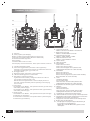
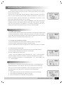
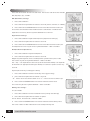
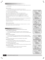
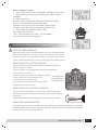
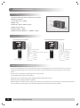
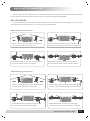
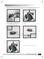
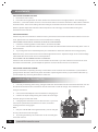
LCD DIGITAL PROPORTIONAL RADIO CONTROL SYSTEM
Operating Manual
INDEX
Transmitter Functions
03
Items Included
04
Specifications
04
Safety Warnings
04
Notice Before Using
05
Transmitter Controls
06
Menu Introduction
07
Other function of the transmitter
11
Receiver Information
12
How To Use The Transmitter
10
Binding your 2.4 GHz Radio System
13
Adjustments
15
Charging The Transmitter
14
Flow Chart
16
Statement: Specifications may change without notice, please refer to the real one for configuration. 2010.07
02
www.blitzrcworks.com
Thank you for purchasing the ETC63- 2.4GHz Radio Control system. For safety
precautions, you must read this manual before operating. BlitzRCWorks and the retailer
are not responsible for any damage or loss resulted from improper usage and mishandling,
as this will be the sole responsibility of the user.
TRANSMITTER FUNCTIONS
The ETC63- 2.4GHz is a newly developed 6 channel proportional transmitter and is the latest
development of Art-Tech RC Hobby Corporation. This radio system uses digital frequency hopping
technology and has an enormous advantage in comparison to the traditional radio systems. The ETC632.4GHz Radio System does not use crystals, prevents frequency interference, uses a short antenna, and
has low energy consumption.
FEATURES:
1. Flight time display of seconds and minutes.
2.Voltage display- includes a low voltage alarm. A red LED flash is visible when battery voltage is lower
than 8.5V.
3.Channel output reverse set.
4. Up to 5 types of aircraft modes to choose from; contains 12 independent aircraft data storage and call.
5.Mode 1 and Mode 2 available.
6.Throttle protection to avoid danger of motors starting suddenly when
throttle hold switch is turned on. The throttle output value will be set to
the minimum. When restarting the transmitter for any reason and the
throttle output value is not set to the minimum, the red LED flashes an alarm as shown in the figure. The
throttle will automatically set to the minimum value setting and the transmitter will lock. When the
transmitter is adjusted properly, the transmitter will unlock itself.
7.Channels 1, 2, and 4 uses DR (Dual Rate) and EXP (Exponential Curve) settings.
8.All channels operate on EPA (end of the process) setting.
9.Channel 5 operates on a two-state setting includes gyroscope sensitivity setting for helicopters and
landing gear set up for fixed-wing airplanes.
10.Channels 3 and 6 using general and 3D mode curve setting for general and CCPM helicopters
11.Four groups of channel mixing controls
12.All channel output dynamic display
13.All channel midpoint regulation
14.Ability to restore to factory settings
15.Channels 1 through 6 auxiliary fine-tune settings
www.blitzrcworks.com
03
ITEMS INCLUDED
1. Transmitter: ETC63-2.4GHz
2. Receiver: ER62-2.4GHz
3.Manual
The spare parts below is only offered in a complete set:
3 AS-100 9g Servos
Simulator Cable
Belt
9.6V Ni-MH Battery
Charger
CD Rom
Specifications
Number of channels: 6
Color: Black
Charging Jack: Included
Antenna Length: 15cm
3D Switch: Included
Can be used on: Airplanes, and Helicopters
Power Supply: 12V (1.5V, 8 AA Batteries)
Certification: FCC, CE, RoHS
Voltage Display: LCD
SAFETY WARNINGS
CLIMATE CONTROL: Do not operate your aircraft in the rain or in the
presence of a strong wind. Water can damage the transmitter and may
cause your aircraft to lose control. This can cause a crash and even
lead to serious injuries.
BIND BUTTON: Make sure the frequency bind button is up and not
pressed down. The radio system may need to rebind again. You can
find the information on binding your radio system in this manual.
BINDING: Only bind one radio system at a time. Do not try to bind
more than one receiver to a transmitter or more than one transmitter
to a receiver. Make sure you turn off your other RC devices while
binding.
PREFLIGHT TEST: Always perform a mandatory preflight test by
testing all of your controls before flight. You may need to adjust your
settings to ensure a good flight. A range test is also a must before
flight. You can do so by testing the controls of your aircraft with your
transmitter at a close distance and then slowly walk further
away. A few hundred feet would be a good distance to test.
APPROPRIATE LOCATIONS: DO NOT fly near houses,
at an airport, near any power lines or on the street and
roads. You may be fined and can also caused damages
to your surroundings and injuries. Please also do not fly
in a crowded area.
04
www.blitzrcworks.com
NOTICE BEFORE USING
SIGNALS TO BE AWARE OF
Please pay close attention to these signs below. They will appear in this manual as you read.
Signal
Figure
Indicates
WARNING
Improper operation may cause damages and injuries
CAUTION
Improper operation may cause damages and injuries
STORAGE INFORMATION
▲ DO NOT place the radio system in:
Extremely hot or cold locations above 60ºC or below 10ºC
Under sunlight for a long period of time
Damp surfaces
▲ If you are going long periods of time without using this radio system, remove the batteries from the
battery compartment and store it in a dry and cool area.
▲ DO NOT clean the radio system with a chemical solvent known as Acetone.
▲ DO NOT discard used batteries in the trash. It should be stored in a non-metal container and to
be dispatched of properly.
▲ Please use rechargeable batteries when possible to reduce pollution.
Attention
When opening the transmitter battery compartment or turning on the transmitter, the throttle stick
must be all the way down first.
Before turning off the transmitter, make sure to pull the throttle stick and throttle trim setting all the
way down first. TURN OFF THE AIRCRAFT FIRST BEFORE TURNING OFF THE TRANSMITTER.
Turning off your transmitter before your aircraft can be potentially dangerous and your aircraft may
somehow pick up a signal and act as if it has a mind of its own.
Lower your throttle settings all the way down before you adjust your transmitter settings. Pay close
attention to the motor during your adjustments. This receiver will only operate with its respective
transmitter and is not compatible with another brand transmitter.
DO NOT adjust factory settings if you are unsure and do not fully understand what type of performance
you want out of your aircraft. This will affect the controls on your transmitter.
www.blitzrcworks.com
05
TRANSMITTER CONTROLS
A
B
W
C
E
F
D
G
H
I
K
M
J
L
N
P
O
S
T
U
Q
R
V
A:Antenna
B:LCD(Liquid Crystal Display)
·Battery voltage of transmitter (battery energy level)
·Channels are on NOR or REV (Normal or Reversed)
·Estimated available flight time
·Menu setting
·Indicates state of lock or unlock
·Also displays: channel directions, data, option number, functions
C:Throttle hold toggle switch
D:Channel 5 toggle switch (should be in the up position)
Channel 5 on aircraft can be used for mounted aerial cameras,
retractable landing gear, gyro mode, etc.
E:3D toggle switch
F:D/R toggle switch (should be in the up position)
G:LED for indicating power on transmitter
H:Red LED to indicate low battery.
Light flashes when battery voltage is under 8.5V. LCD will
turn off when voltage is under 7.6V.
NOTE: When this light flashes or that no display shows on
the LCD, change the battery before operating to avoid flying
out of control.
I:Left joystick
If transmitter is on Mode 1, this operates elevator (up and down)
and rudder (left and right).
If transmitter is on Mode 2, this operates throttle (up and down)
and rudder (left and right).
J:Right joystick
If transmitter is on Mode 1, this operates aileron (left and right)
and throttle (up and down).
If transmitter is on Mode 2, this operates aileron (left and right)
and elevator (up and down).
06
X
www.blitzrcworks.com
Y
A1
Z
K:Left vertical trim tab
Mode 1: elevator trim; Model 2: throttle trim
L:Right vertical trim tab
Mode 1: throttle; Mode 2: elevator
M:Left horizontal trim tab
Mode 1: rudder; Mode 2: rudder
N:Right horizontal trim tab
Mode 1: aileron; Mode 2: aileron
O:Power switch
P:Neck strap hook
Q:Menu button
Enters into main menu
Enters into sub main menu
Enters into time page menu (release after
holding down the button for a few seconds)
R:Sub button
Enters into sub menu
Enters into sub sub-menu
Enters into time page menu (release after holding
down the button for a few seconds)
S:Y/UP
Validates selection
Increase data input
Puts channel in normal mode (release after
holding down the button for a few seconds)
T:Right button for selecting right in the display
U:N/Down
Cancels selection
Decrease data input
Puts channel in reverse mode (release after
holding down the button for a few seconds)
V:Left button for selecting left in the display
W:Steel handle for ease of carrying and transportation
X:Bind button to be used for establishing a connection
between the transmitter and receiver
Y:Plug port for simulator software connecting cable
Z:Battery bay for AA batteries
A1:Charging port to plug charging cable directly to
transmitter to charge batteries
NOTE: Only 9.6V Ni-MH battery packs can be
recharged.
MENU INTRODUCTION
After turning on the radio, the screen displays the time page. Press menu
several times to enter into the main menu. Press the sub button at this time to
enter into the sub menu.
There will be a single beep sound to indicate a button pressed. If you do not
hear any sound after pressing a button, check if the button is in place. It may
be that the button you have pressed is not applicable in this menu so try
pressing another button to hear for any sounds.
When the special function button (Y/UP or N/DOWN) is pressed, there will be
3 beeping sounds in descending pitches. When the menu setting is complete,
press the menu button or sub button for a couple of seconds to hear the 2
beeping sounds then release the button to return to the time page.
1.MODE SELECTION
1.1 Flying mode settings:
1. Press the menu button and then enter into the data storage menu (mode select).
2. Press the right button and then Y/UP button to confirm. As shown in the figure
on the right, the top left of the display area shows the abbreviation of the selected
mode 1. Yes means that the chosen mode is set at “A”.
1.2 Storing data for different models:
1. Press the sub button to enter into the mode menu (the save function).
2. Press the left or right button to choose a storage location.
3. Press Y/UP button to confirm storage. You can store up to a total of 12 models.
1.3 Selecting the stored mode:
1. Press the sub button to enter into the data call menu (the load function).
2. Press the left of right button to choose a stored model.
3. Press Y/UP button to confirm data.
“Load” means that the data value is being set now. “Non” means that there
has been no data stored in this location. As shown in the figure on the right, H
means the stored information is in a helicopter mode. “R” means Model 1 and
“L” means Mode 2.
2.SERVO REVERSE SETTINGS
Servo reversing is where the control input of that servo is running opposite of
the desired direction. For instance, if one of your aileron servo is moving up
when you are commanding it to go down, and it is going down when you are
trying to position it up, then you can reverse the servo through your
transmitter.
1.
Press the menu button to enter into the Rev menu (servo reversing).
2.
Press the left or right button to choose a channel.
3.
Press Y/UP button to change the reversing setting.
www.blitzrcworks.com
07
3.POPULAR OPTIONS
Press the menu button to enter into Set menu. There are 5 sub menus that include
D'R, Exp, Epa, Gyr, and Mrv.
D'R (Dual Rate) settings:
1.
Press the sub button
2.
Press the left or right button to choose a channel (aileron, elevator, or rudder).
3.
Press the Y/UP or N/DOWN button to increase or decrease the value input.
The values set take effect when the D'R switch is switched on. The Dual Rate
exponential curve may be set anywhere between 0% and 125%.
Exponential settings:
1.
Press the sub button to get to the Exp menu (exponential settings).
2.
Press the left or right button to choose a channel.
3.
Press the Y/UP or N/DOWN button to increase or decrease the value input.
The exponential curve may be set to anywhere between -100% and 100%.
EPA (End Point Adjustment):
1.
Press the sub button to go to the Ep menu.
2.
Press the left or right button to choose a channel.
Negative symbol signifies minus and the positive symbol means plus or add.
The values may be set anywhere between -100% and 100%.
The “Ep-“corresponds to to one half trip of the stick while the Ep+ corresponds
to the other half. Appropriate settings of the Ep can achieve a 3 point curve of any
channel.
Gyroscope sensitivity/ landing gear setting:
1.
Press the sub button to enter into the Gry menu (gyro mixing).
2.
Press the left or right button to choose a channel.
“d” means channel 5 switch is down and “u” means channel 5 switch is up.
3.
Press Y/UP or N/DOWN button to increase or decrease the value.
This value may be set anywhere between -100% and 100%.
Mixing rate settings:
In A,V, D mode
1.
Press the sub button to inter into the Mrv menu (mixing rate settings)
2.
Press the left or right button to choose an option.
A is for aileron, E for elevator, and R for rudder.
3.
Press Y/UP or N/DOWN button to increase or decrease the setting value.
The value -100% to 100% indicates the actual output mixing rate.
08
www.blitzrcworks.com
In C mode
1. Press the sub button to inter into the Swash menu (swash rate setting).
Figure 1 shows 120º CCPM while Figure 2 shows 90º CCPM.
2. Press the Y/UP or N/DOWN button to connect the aileron to channel 1 or
6, elevator to channel 2, and pitch to channel 6 or channel 1 (not occupied by
aileron).
A is for aileron, E for elevator, and R for rudder.
3. Press the left or right button to choose an option.
A is for aileron, E for elevator, and P for pitch.
4. Press the Y/UP button or N/DOWN button to increase or decrease the
setting value.
The value -100% to 100% indicates the actual output mixing rate.
4.CURVE SETTINGS
Press the menu button to enter into the Cuv menu. There are 4 submenus
that include Thr, Pit, T3d, and P3d. Switch on the 3D and the 3D curve can be
activated.
Normal throttle settings:
1. Press the sub button to enter into the Thr menu (normal throttle curve
function).
2. Press the left or right button to choose a key point to set to.
5 key points corresponds to the channel trip of 0%, 25%, 50%, 75%, and 100%.
3. Press Y/UP or N/DOWN button to increase or reduce the value.
The value may be set to anywhere between 0% and 100%.
Normal pitch settings:
1. Press the sub button to enter into the Pit menu (normal throttle curve
function).
2. Press the left or right button to choose a key point to set to.
5 key points corresponds to the channel trip of 0%, 25%, 50%, 75%, and 100%.
3. Press Y/UP or N/DOWN button to increase or reduce the value.
The value may be set to anywhere between 0% and 100%.
3D throttle settings:
1.
Press the sub button to enter into the T3d menu (3D pitch curve function).
2. Press the left or right button to choose a key point to set to.
5 key points corresponds to the channel trip of 0%, 25%, 50%, 75%, and 100%.
3. Press Y/UP or N/DOWN button to increase or reduce the value.
The value set takes effect when the 3D switch is turned on.
The value may be set to anywhere between 0% and 100%.
3D pitch settings:
1.
Press the sub button to enter into the P3d menu (3D pitch curve function).
2. Press the left or right button to choose a key point to set to.
5 key points corresponds to the channel trip of 0%, 25%, 50%, 75%, and 100%.
3. Press Y/UP or N/DOWN button to increase or reduce the value.
The value set takes effect when the 3D switch is turned on.
The value may be set to anywhere between 0% and 100%.
www.blitzrcworks.com
09
5.MIXING SETTINGS IN A, V, D MODE
Press the menu button to enter into the Mix menu (mixing). There are 2 sets
of mixing settings
Mixing settings:
1. Press the sub button to enter into the Mix1 menu (mixing 1).
2. Press the left or right button to choose an option of using the master channel,
slave channel or mixing proportion.
3. You can choose to use this option:
Press Y/UP or N/DOWN button to confirm Yes or No (to cancel).
Master channel option (Mas): press Y/UP or N/DOWN button to select it.
Slave channel option (Slv): press Y/UP or N/DOWN button to select it.
Mixing proportion setting: press Y/UP or N/DOWN button to set the mixing
proportion.
The slave channel is under control of the master channel at the setting proportion.
The value may be set to anywhere between 0% and 100%.
Reasonable settings of MIX make flight of delta wing or V-tail aircraft 2 channel
mixing easy to control.
Mixing channel settings:
Press the sub button to enter into the Mix2 menu (mixing channels 2, 3, and 4).
Some specific settings are the same as Mix1.
6.OTHER FUNCTIONS
Press the menu button to enter into the Pls menu (plus function).
Channel display and calibration:
1. Press the sub button to enter into the Chv menu to view the channels.
2. Press the left or right button to choose a channel. The channel output trip will
be displayed.
Restore to factory settings:
1. Press the sub button to enter into the Bak menu (back to original setting).
2. Press the Y/UP or N/DOWN button to confirm or cancel restoring to factoring
settings.
3. Press the Y/UP button to confirm the resetting to factory settings.
Calibrating the settings:
1. Press the left or right button to enter into the calibrate menu.
2. Press the Y/UP button and have the transmitter joysticks set to neutral and
the throttle stick all the way down.
3. Press the N/DOWN button to confirm.
In this calibration process, output values of all channels are set to the initial values.
Auxiliary trim settings:
1. Press the sub button to enter into the Trm menu (trim settings).
2. Press the left or right button to select a channel.
10
www.blitzrcworks.com
Mode 1 and Mode 2 settings:
1. Press the sub button to enter into the Mode 1 and Mode 2 settings menu.
2. Before setting the mode, make sure the plane is turned off (battery is
unplugged).
3. Adjust the joysticks.
The screws shown in the figure A and B help to suppress the springs.
Screws C and D adjusts the resistance of the sticks.
For Mode 1, loosen screws A and C but tighten screws B and D/
For Mode 2, loosen the screws for B and D but tighten A and C.
4. Press the left or right button to select a mode.
Press Y/UP button to confirm.
“left” stands for Mode 2 and “right” stands for Mode 1.
You can now finish the channel calibration.
C
A
B
D
OTHER FUNCTIONS OF THE TRANSMITTER
LOW VOLTAGE WARNING
When the voltage of the transmitter battery is low, the red LED will flash.
When this light flashes, it is best to bring your aircraft back down and to
stop flying until you have charged the battery. Ignoring this warning can
cause crashes and damages to your aircraft along with possible injuries.
ADJUSTING THE JOYSTICK SPRING
The joystick spring can be adjusted and it is possible to adjust the
aileron, elevator, or rudder.
1. Turn the screw on the transmitter back counterclockwise to
remove the back covering.
2. Turn the screw of the channel to adjust the spring.
screw adjustment
Turn it clockwise for more resistance and
screw adjustment
screw adjustment
counterclockwise to make it loose.
3. Put the back of the transmitter back into place
and tighten the screws to close.
ADJUSTING THE JOYSTICK'S LENGTH
1.Turn the head of the joystick counterclockwise to extend the length
Counterclockwise to extend
and clockwise to shorten. Please do not extend it too much as it can fall
off or break.
2.Tighten the lower part of the joystick by turning it counterclockwise.
USING THE CHARGING PORT
Clockwise to shorten
The charging port is located on the side of the transmitter and is specifically designed for charging the
transmitter battery with the battery still in the transmitter. Please make sure the batteries are installed
correctly and to not overcharge the battery.
www.blitzrcworks.com
11
RECEIVER INFORMATION
Specifications
Indication that the receiver is working if it is tested
between 4.8V to 6V
Current drain rate: < 40mA
Weight: 12g
Dimension: 44mm x 23mm x 15mm
Number of channels: 6
Range in height: > 350m
Adjacent channel rejection: > -85dBm + 16kHz
Function
Connections for helicopters
Connections for airplanes
CH
CH
RECEIVER
ER61-2.4GHz
RECEIVER
ER61-2.4GHz
B. Battery/Bind
B. Battery/Bind
6. Pitch
6. Pitch
5. Gyro gain
5. Landing Gear Retracts/ Bomb doors
4. Rudder
4. Rudder
3. Throttle
3. Throttle
2. Elevator
Signal
+
-
1. Aileron
2. Elevator
Signal
+
-
1. Aileron
POWER SUPPLY FOR THE RECEIVER
The receiver operates on an input of DC power given from plugging in the circuit and servo wires. The input
voltage should be between 4.8V and 6V. The electric current is 0.25A of the receiver plus the current of the
servos.
Three common methods of supplying power to the receiver:
1.A separate battery pack for the receiver.
2.ESC (Electronic Speed Controller) with BEC (Battery Eliminate Circuit).
3.Receiver power supply distributor (UBEC).
NOTE: Please remember to fully charge your battery for the aircraft and your transmitter for the best performance.
If your batteries are running low, your aircraft might not have enough power to fly properly.
12
www.blitzrcworks.com
HOW TO USE THE TRANSMITTER
The correct power up process is to turn on the transmitter first with the throttle stick and throttle trim settings
all lowered to its lowest position before turning on your aircraft.For operating helicopter
ON A HELICOPTER
If you are unfamiliar with how the helicopter can react to your commands on the transmitter or how to control
your helicopter with the transmitter, you can see how it operates below.
Mode 1 Helicopter Instructions:
Ailerons: Move left joystick left for the helicopter to
Elevator: Move left joystick up to have helicopter
move left;move stick right to move right.
tail end up; move joystick down to have tail end down.
Throttle: Move right joystick up for more power/lift;
Rudder: Move right joystick left to turn helicopter
move joystick down to decrease in power.
counterclockwise; move joystick right for clockwise.
Mode 2 Helicopter Instructions:
Ailerons: Move right joystick left for the helicopter to
Elevator: Move right joystick up to have helicopter
move left; move stick right to move right.
tail end up; move joystick down to have tail end down.
Throttle: Move left joystick up for more power/lift;
Rudder: Move left joystick left to turn helicopter
move joystick down to decrease in power.
counterclockwise; move joystick right for clockwise.
www.blitzrcworks.com
13
ON AN AIRPLANE
If you are unfamiliar with how the airplane can react to your commands on the transmitter or how to
control your airplane with the transmitter, you can see how it operates below.
Mode 1 Airplane Instructions:
Ailerons: Move left joystick left for the left aileron to
Elevator: Move left joystick up to have elevators
go down and right aileron to go up.Move left joystick
(horizontal tail) go up for the plane to rise up.Move left
right for the left aileron to go up and right aileron to
joystick down to have elevators go down for the plane
go down.
to lower to the ground.
Throttle: Move right joystick up for more power/lift;
Rudder:Move right joystick left to have rudder (vertical
move joystick down to decrease in power.
tail) turn left for the plane to turn left.Move right joystick
right to have rudder turn right for the plane to turn right.
Mode 2 Airplane Instructions:
14
Ailerons: Move right joystick left for the helicopter
Elevator: Move right joystick up to have elevators
to move left; move stick right to move right.
(horizontal tail) go up for the plane to rise up.
Throttle: Move right joystick down to have elevators
Rudder:Move left joystick left to turn helicopter
go down for the plane to lower to the ground.
counterclockwise; move joystick right for clockwise.
www.blitzrcworks.com
BINDING YOUR 2.4GHZ RADIO SYSTEM
If this radio system is being used on a nitro gas powered aircraft, please connect the throttle into
another channel first and then plug it into BATT channel on the receiver after binding.
1. Plug in the short-circuit plug (bind plug
as shown with a small looped wire at the
end) into the BATT channel on the receiver.
Connect the ESC to the receiver for
electricity to be sent to the motor.
2. Press the bind button on the back of
your transmitter and then turn on the
transmitter
3. A light will be visible to indicate that the
bind process is complete and was successful.
4. Unplug the bind plug and there will be
a flashing light.
5. Press bind button up into “work mode.”
www.blitzrcworks.com
15
ADJUSTMENTS
ADJUSTING CHANNEL VALUES
1.
Enter into the Chv menu.
2.
Press the left or right button to check whether the channels are in the right positions. Your settings for
channels 1, 2, and 4 should be set to 0%. The minimum value of channel 3 should be -100% and the maximum
should be 100%. If the curve setting value has changed, it should be set to the set value. If the values are
different, please adjust the channels and its mid points. This is strongly recommended for using this
transmitter for the first time.
SERVO REVERSING
Check every servo's movement to make sure every movement of the control arms and servo arms are correct.
If not, please enter into the Rev menu to reverse that servo's setting.
ADJUSTING POSITIONS OF AILERON, ELEVATOR, AND RUDDER
1.
Check the centering position of the aileron, elevator and rudder.
2.
Turn on the transmitter first and then lower the throttle stick and throttle trim tab all the way down. Turn on
the aircraft last.
3.
Try moving each servo individually with your transmitter to make sure that each are moving properly.
Make sure every servo control arm is set at a 90º angle with the servo. Adjust the length of the control linkage
rod and that the control arms are in a neutral position.
ADJUSTING THE MOVEMENT RANGE OF SERVOS
Check for how much each servo can move and that it is centered. If you aren't able to move the servo much
and seem to be restricted, you can adjust the position on of the clevis on the servo control arm.
ADJUSTING THROTTLE CONROL
Check if the throttle is operating correctly in accordance to the controls on the transmitter. If your throttle is
going full when the stick is all the way down and that it is powering down when you push the throttle stick up,
you can adjust it by reversing the throttle in channel 3.
CHARGING THE TRANSMITTER
Procedure:
1.
Correctly and safely power off by pulling throttle stick and throttle trim all lowered first and then turn off
aircraft and transmitter last. Transmitter must be turned off in order to charge. The transmitter cannot
charge if it is still on.
2.
Connect the wall adapter to the transmitter's charging port.
3.
Check if the input voltage rating is the same as the charger
and then plug it into the wall outlet.
4.
Charging time should be no more than 5 hours. If you have
not used or operated the transmitter in a while, it is best to
recharge it before using again.
Note:
1.
Only the 9.6V Ni-HM rechargeable battery can be charged.
The dry cell should not be charged
2.
To prolong the battery life, make sure not to overcharge at
more than 5 hours.
16
www.blitzrcworks.com
SUB
RIGHT
LEFT
N/DOWN
Flow Chart
(1-9,A,b,C)
(1-9,A,b,C)
(CH1-6)
Key
(CH1,2,4)
Menu
Sub
Left
right
y/up
n/down
(CH1,2,4)
(CH1-6)
(A , E , r)
(A,V,D)
(A , E , P)
(C)
(PT1-5)
(H, C)
(PT1-5)
(PT1-5)
(PT1-5)
(A,V,D)
(Mix 2,3,4 Set as Mix 1 )
(CH1-6)
(CH1,2,4,6)
www.blitzrcworks.com
17
www.blitzrcworks.com