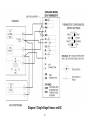
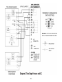
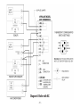
1
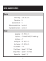
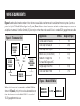
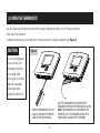
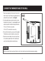
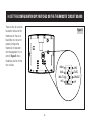
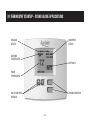
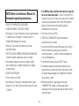
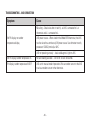
Premium Programmable Thermostat
Safety & Installation
Instructions
Model 8570
READ AND SAVE THESE INSTRUCTIONS
TABLE OF CONTENTS
PAGE
PAGE
SPECIFICATIONS . . . . . . . . . . . . . . . . . . . . . . . . . . . . 1
5. WIRE THE THERMOSTAT TO THE
HVAC EQUIPMENT . . . . . . . . . . . . . . . . . . . . . . 8
WIRE REQUIREMENTS. . . . . . . . . . . . . . . . . . . . . . . . 2
Diagram 1 – Single-Stage Furnace and AC . . . . . . 9
1. SELECT A MOUNTING LOCATION. . . . . . . . . . . 3
Diagram 2 – Two-Stage Furnace and AC . . . . . . 10
2. OPEN THE THERMOSTAT . . . . . . . . . . . . . . . . . 4
Diagram 3 – Two-Stage Roof Top Unit . . . . . . . . 11
3. MOUNT THE THERMOSTAT BASE
TO THE WALL . . . . . . . . . . . . . . . . . . . . . . . . . . . 5
4. SET THE CONFIGURATION DIP SWITCHES
ON THE THERMOSTAT CIRCUIT BOARD . . . . . 6
Diagram 4 – Boiler with AC . . . . . . . . . . . . . . . . 12
Diagram 5 – Radiant Floor 1st Stage Heat
with Furnace 2nd Stage Heat and AC . . . . . . . . . 13
Diagram 6 – Single-Stage Heat Pump . . . . . . . . 14
Diagram 7 – Two-Stage Heat Pump . . . . . . . . . . 15
6. OPTIONAL – INSTALL AN OUTDOOR
TEMPERATURE SENSOR . . . . . . . . . . . . . . . . . 16
PAGE
PAGE
7. OPTIONAL – INSTALL AN AUTOMATIC
HUMIDIFIER CONTROL (AHC) . . . . . . . . . . . . . 19
10. CUSTOMIZE THE
APPLICATION SETTINGS . . . . . . . . . . . . . . . 30
8. OPTIONAL – INSTALL AN INDOOR
TEMPERATURE SENSOR . . . . . . . . . . . . . . . . . 21
Differential . . . . . . . . . . . . . . . . . . . . . . . . . . . . 30
9. THERMOSTAT STARTUP . . . . . . . . . . . . . . . . . 23
Progressive Recovery . . . . . . . . . . . . . . . . . . . . 31
Verify Outdoor Temperature Sensor . . . . . . . . . . 24
Balance Points (Heat Pumps Only) . . . . . . . . . . . 32
Check Fan Operation . . . . . . . . . . . . . . . . . . . . . . 24
Input Dealer Contact Information . . . . . . . . . . . 33
Verify AHC Connection . . . . . . . . . . . . . . . . . . . . 24
Blower Extension for Humidity Control . . . . . . . 34
Check Heating Operation . . . . . . . . . . . . . . . . . . 26
Monitors – Air Filter, Service Humidifier,
UV Lamp, Service HVAC . . . . . . . . . . . . . . . . . . 35
Check Cooling Operation . . . . . . . . . . . . . . . . . . 28
Check Emergency Heat Operation
(Heat Pumps Only) . . . . . . . . . . . . . . . . . . . . . . . 29
Offset . . . . . . . . . . . . . . . . . . . . . . . . . . . . . . . . 31
SAFETY INSTRUCTIONS
Read this Installation Manual before beginning installation of the Aprilaire® 8570 Thermostat. For questions call
Research Products Corporation at (800) 334-6011.
WARNING
1. 120 Volts may cause serious injury from electrical shock. Disconnect electrical power to the HVAC equipment before
starting installation. This thermostat is not a 120-volt (line voltage) device.
2. Improper installation may cause serious injury from electrical shock. This product must be installed by a qualified
heating and air conditioning contractor in accordance with NEC Standards and applicable local and state codes.
3. Mercury is toxic and may be hazardous to health. Any replaced thermostats containing mercury must be disposed of
properly. Contact local authorities for disposal information.
MODEL 8570 SPECIFICATIONS
Electrical
Thermostat Voltage:
Total Load Current:
Single Output Load Current:
Solid State Output Residual Current:
Voltage Drop at Solid State Outputs:
24-volts ± 20% AC or DC
2A
1A
Less than 5 mA
Less than 1-volt
Thermal
Operating Range:
Display Accuracy:
Control Accuracy:
Control Range Heat:
Control Range Cool:
Heat/Cool Deadband:
1st Stage Differential:
2nd Stage Differential:
Temperature Offset:
32°F – 99°F (0 C – 37 C)
±1°F between 60°F and 80°F, ±2°F outside this range
±1°F
40°F – 88°F (4 C – 30 C)
42°F – 90°F (6 C – 32 C)
2°F or C
Adjustable 1°F – 3°F (1°F default)
Adjustable 1°F – 3°F (1°F default)
Adjustable 1°F – 4°F
-1-
WIRE REQUIREMENTS
Figure 1 and the table show the number of wires that must be available at the thermostat in stand-alone thermostat systems (i.e. not as
part of an Aprilaire® Model 6504 Intelligent Zone System). Figure 1 shows optional connections to both an outdoor temperature sensor and
an Aprilaire® Automatic Humidifier Control (AHC), but only one or the other can be used. All wire is standard 18-24 gauge thermostat cable.
Application
Figure 1 – Thermostat Wire
OPTIONAL –
AUTOMATIC
HUMIDIFIER
CONTROL
(AHC)
OPTIONAL –
OUTDOOR
TEMPERATURE
SENSOR
2-WIRES
HVAC
EQUIPMENT
2-WIRES
SEE
TABLE
OPTIONAL –
INDOOR
TEMPERATURE
SENSOR
2-WIRES
# Wires
5
1 (9)
Two-Stage Furnace/AC
7
2 (10)
Two-Stage Roof Top Unit
7
3 (11)
Boiler w/AC (2-transformer)
6
4 (12)
Radiant 1st Stage Heat,
Furnace 2nd Stage and AC
6
5 (13)
Single-Stage Heat Pump
6
6 (14)
Two-Stage Heat Pump
8
7 (15)
MODEL 8570
THERMOSTAT
Figure 2 – Model 6504 Wire
When this thermostat is connected to a Model 6504 as
shown in Figure 2, only one four-wire cable need be run
from the thermostat to the Model 6504. Use standard
18-24 gauge thermostat cable.
Diagram (Page)
Single-Stage Furnace/AC
MODEL 8570
THERMOSTAT
-2-
4-WIRES
MODEL 6504
(1) SELECT A MOUNTING LOCATION
If installing the thermostat alone…
• Mount on an interior wall, in a frequently occupied space.
• Keep the thermostat 18" from an outside wall.
• Mount the thermostat approximately 5 feet above the floor.
Height requirements are different for compliance with the
Americans with Disabilities Act (ADA) – 48" maximum height
for forward reach and 54" maximum height for side reach.
• Thermostat can be mounted to a vertical junction box (j-box).
• DO NOT mount the thermostat:
– behind doors, in corners or other dead air spaces.
– in direct sunlight or near lamps, appliances or other
sources of heat.
– on an outside wall or wall exposed to an unconditioned
space (i.e. garage).
– in the flow path of a supply register, in stairways or near
outside doors.
– on a wall where concealed pipes or ductwork could
influence the sensor.
– near sources of electrical interference such as arcing
switch contacts.
If installing an indoor temperature sensor…
• Mount the thermostat where it can be readily accessed.
Note that the backlighting illuminates whenever a button
is pressed.
• Thermostat can be mounted on a vertical junction box (j-box).
• DO NOT mount the thermostat where the operating range
temperatures will be exceeded (i.e. attic or unventilated
equipment room).
• Mount the sensor in the same location as if installing a
thermostat alone.
-3-
(2) OPEN THE THERMOSTAT
Use your hands to pull the thermostat face off of the base. Separate one side at a time. There are latches on
either side of the thermostat.
If needed, the thermostat can be pried from the base by inserting a flat-head screwdriver (see Figure 3).
CAUTION
Figure 3
Loss of internal programs
may result from static
discharge to thermostat
circuit board. Avoid
touching the circuit board
and touch a grounded
metal object before
handling the thermostat.
INSERT SCREWDRIVER INTO 1 OF
4 SLOTS (2 ARE ON THE TOPSIDE,
2 ARE ON THE BOTTOM SIDE)
-4-
USE THE SCREWDRIVER TO SEPARATE THE
HOUSINGS. REPEAT ON THE REMAINING 3 SLOTS.
NOTE: THE HOUSINGS WILL NOT COMPLETELY
SEPARATE. PULL THE HOUSINGS APART WITH
YOUR HANDS TO COMPLETELY SEPARATE.
(3) MOUNT THE THERMOSTAT BASE TO THE WALL
1. Place the wire opening in the base over the wire entry
hole in the wall. Level the base (for appearance only)
and mark the screw locations. See Figure 4.
Figure 4
2. Use the supplied screws and wall anchors to mount
the thermostat to the wall. It is recommended that wall
anchors be used for installation to drywall/sheet rock.
• Drill a 3/16" hole for wall anchors.
W2
W1
RH
• Drill a 3/32" starter hole for screws only.
R
RC
3. For junction box mounting, screws are field supplied.
The thermostat can be installed on a vertical j-box.
G
4. Seal the wire entry hole(s) with caulk, drywall putty
or insulation to prevent drafts from inside the wall
cavity from affecting thermostat performance.
IDS
Y1
ODT
Y2
CIR
GND
B
ZA
O
ZB
I+
C
I-
CAUTION
Minimize wire entry hole size and seal the hole – drafts from inside the wall could affect temperature readings.
-5-
(4) SET THE CONFIGURATION DIP SWITCHES ON THE THERMOSTAT CIRCUIT BOARD
There are four dip switches
located on the back of the
thermostat (on the circuit
board) that must be set to
properly configure the
thermostat for operation
with the equipment it is to
control. Figure 5 shows
the default position for the
four switches.
Figure 5
6504
-6-
AHC
ON
GAS
MULTI
H/C
ELEC
SINGLE
HP
6504 or AHC – This switch is used to configure the thermostat
installation as part of a Model 6504 Intelligent Zone System.
• Set to 6504 only if installing as part of a Model 6504
Intelligent Zone System.
• Set to AHC if the thermostat is to be wired to the
HVAC equipment or standard zone system.
GAS or ELEC – When set to ELEC, the fan terminal (G) will
be energized on a call for heat.
• Set to ELEC when the heat source is electric
(such as strip heat).
• Set to GAS when the heat source is fossil fuel (oil, propane,
natural gas). For heat pumps, when set to FOSSIL, the
compressor terminal(s) will de-energize before the auxiliary
heat terminal (W1) is energized, thus acting as a fossil fuel kit.
MULTI or SINGLE – When set to single, the second stage
outputs (Y2 and W2) do not energize.
• Set to SINGLE for single-stage furnace/AC applications or
single-stage compressor heat pump systems.
• Set to MULTI if the furnace or air conditioner is two-stage
or if the heat pump has a two-stage compressor.
HEAT/COOL or HEAT PUMP – When set to HP the compressor
terminal (Y1) is the first stage output for both heating and cooling.
• Set to HP when installed with heat pumps.
• Set to H/C when installed with furnace/AC systems,
roof top units or boiler/AC combination systems.
STOP!
If installing this thermostat as part of a Model 6504 Intelligent Zone System, refer to the Model 6504
Installation Manual for wiring and checkout procedures. Continue Model 6504 installation with Step 10 (page 30).
If wiring this thermostat directly to the HVAC equipment or standard zone control panel, continue with Step 5.
-7-
(5) WIRE THE THERMOSTAT TO THE HVAC EQUIPMENT
WARNING
120 volts may cause serious injury from electrical shock. Disconnect electrical power to the furnace
and air conditioner before starting installation. This thermostat is not a 120 volt (line voltage) device.
1. Run a cable with the correct number of wires
(see table) from the thermostat to the HVAC equipment.
2. Strip 1/4" of insulation from the end of the wires to
be connected to the thermostat.
3. Strip no more insulation than is required to make a
sound electrical connection at the HVAC equipment.
4. Wire the thermostat to the HVAC equipment according
to the wiring schematic appropriate for your HVAC
equipment.
Application
# Wires
Diagram (Page)
Single-Stage Furnace/AC
5
1 (9)
Two-Stage Furnace/AC
7
2 (10)
Two-Stage Roof Top Unit
7
3 (11)
Boiler w/AC (2-transformer)
6
4 (12)
Radiant 1st Stage Heat,
Furnace 2nd Stage and AC
6
5 (13)
Single-Stage Heat Pump
6
6 (14)
Two-Stage Heat Pump
8
7 (15)
-8-
Diagram 1: Single-Stage Furnace and AC
-9-
Diagram 2: Two-Stage Furnace and AC
- 10 -
Diagram 3: Two-Stage Roof Top Unit
- 11 -
Diagram 4: Boiler with AC
- 12 -
Diagram 5: Radiant Floor 1st Stage Heat with Furnace 2nd Stage Heat and AC
- 13 -
Diagram 6: Single-Stage Heat Pump
- 14 -
Diagram 7: Two-Stage Heat Pump
- 15 -
(6) OPTIONAL – INSTALL AN APRILAIRE MODEL 8052 OUTDOOR TEMPERATURE SENSOR
Note: If an AHC is to be installed, do not wire
an outdoor temperature sensor– see Step 7.
The AHC uses its own outdoor temperature
sensor, which can be read by the thermostat.
1. Mount the outdoor temperature sensor
(see Figure 6).
• Locate on the North side of the building if
possible. East and West are acceptable
locations as long as the sensor will not be
exposed to direct sunlight.
• Mount above anticipated snow line.
• Mount at least 3 feet away from exhaust
vents and condensing units.
• Maximum wire length from sensor to
thermostat is 300 feet.
• Under a soffit or under a wall overhang are
recommended areas for mounting the sensor.
• Follow any additional location requirements
found on sensor installation instructions.
Figure 6
NORTH, EAST
OR WEST SIDE
OF BUILDING
SENSOR WITH
BRACKET
ABOVE SNOW LINE
- 16 -
2. Run a 2-wire cable from the sensor to the thermostat.
CAUTION
Do not run the wire along side line
voltage (120 VAC) or higher lines as this can cause
erratic readings.
3. Take a resistance measurement before connecting to the
ODT and CIR GND terminals to verify the sensor is
properly installed. Measure the wires at the thermostat to
account for wire splices.
• Use an ohmmeter to measure the resistance (kΩ) of
the sensor. The resistance reading will depend on the
outdoor temperature (see table).
4. Wire the sensor to the thermostat (see Figure 7).
• Strip 1/4" of insulation from the two sensor wires.
• Connect the sensor wires to the ODT and CIR GND
terminals of the thermostat. The wiring is not polarity
sensitive, so either wire can be connected to either
thermostat terminal.
- 17 -
OUTDOOR TEMPERATURE (°F)
RESISTANCE (kΩ)
-30
230.6
-20
163.8
-10
117.6
0
85.4
10
62.6
20
46.3
30
34.6
40
26.1
50
19.9
60
15.3
70
11.9
80
9.4
90
7.4
100
5.9
Figure 7
IDS
ODT
CIR
GND
ZA
ZB
C
- 18 -
(7) OPTIONAL – INSTALL AN AUTOMATIC HUMIDIFIER CONTROL (AHC)
Note: The AHC uses its own outdoor temperature sensor,
which is read by the thermostat. If an AHC is to be installed,
do not wire an outdoor temperature sensor to the ODT
terminal of the thermostat.
1. Mount the AHC and its outdoor temperature sensor.
• Follow the directions provided with the AHC except do not
mount the AHC temperature sensor in a fresh air intake.
The temperature sensor must be mounted outside.
• Maximum wire length from AHC to thermostat is 300 feet.
• The AHC must have constant power. DO NOT power the
AHC through furnace accessory terminals.
• DO NOT operate the AHC in Manual Mode – this will result
in the outdoor temperature shown on the thermostat to
always be 20°F.
3. Wire the AHC to the thermostat (see Figure 8).
• Strip 1/4" of insulation from the ends of the wires.
• Connect the I- terminal of the AHC to the I- terminal of
the thermostat.
• Connect the I+ terminal of the AHC to the I+ terminal of
the thermostat.
4. You will need to power up the thermostat to verify the
connection. Refer to step 5 of THERMOSTAT START UP
on page 24.
5. After completing the thermostat installation, you will also
need to verify proper operation of the AHC – see AHC
installation instructions for details on how this is done.
WARNING
Improper installation may cause serious
injury from electrical shock. Do not power up humidifier
before completing the thermostat installation.
2. Run a 2-wire cable from the AHC to the thermostat.
CAUTION
Do not run the wire along side line voltage
(120 VAC) or higher lines as this can cause erratic readings.
- 19 -
NOR
MA
L
Figure 8
6
7
T
RE ES
S
4
POWER
C
3
F
B
BYPASS
A
OFF
T/ T
E
5
O
2
I+ I- R C
24V
H
ODT
1
AUTOMATIC MODE
B2203201 Rev. B
AHC must be powered by a
continuous supply – do not wire
to furnace accessory terminals.
- 20 -
F
(8) OPTIONAL – INSTALL AN APRILAIRE MODEL 8051 INDOOR FLUSH MOUNT TEMPERATURE SENSOR
1. Mount the indoor temperature sensor.
• Locate the sensor as you would locate a thermostat.
• Maximum wire length from sensor to thermostat is
300 feet.
• Follow the installation instructions provided with
the sensor.
2. Run a 2-wire cable from the sensor to the thermostat.
3. Take a resistance measurement before connecting to
the IDS and CIR GND terminals to verify the sensor is
properly installed.
• Use an ohmmeter to measure the resistance (kΩ) of the
sensor. The resistance reading will depend on the indoor
temperature (see table from OUTDOOR SENSOR
installation section on page 17).
4. Wire the sensor to the thermostat (see Figure 9).
• Strip 1/4" of insulation from the two sensor wires.
• Connect the sensor wires to the IDS and CIR GND
terminals of the thermostat. The wiring is not polarity
sensitive, so either wire can be connected to either
thermostat terminal.
CAUTION
Do not run the wire along
side line voltage (120 VAC) or higher lines as
this can cause erratic readings.
- 21 -
Figure 9
IDS
ODT
CIR
GND
ZA
ZB
C
- 22 -
(9) THERMOSTAT STARTUP – STAND ALONE APPLICATIONS
EQUIPMENT
STATUS
MESSAGE
CENTER
OUTDOOR
TEMPERATURE
SETPOINTS
ROOM
TEMPERATURE
UP/DOWN BUTTONS
MULTI-FUNCTION
BUTTONS
- 23 -
• If an AHC has been installed, allow the fan to operate
for no less than 40 seconds. If an AHC is not part of this
installation, you can turn the fan off at any time. A humidity
value can be displayed only after at least 40 seconds of
blower run-time to ensure the humidity reading is
representative of the room air.
NOTE: Refer to the Owner’s Manual for
thermostat operating instructions.
1. PLACE THE THERMOSTAT ON THE BASE.
2. TURN ON POWER TO THE HVAC SYSTEM.
• The display will show the Aprilaire screen for approximately
5 seconds (up to 10 seconds if installed as part of a
Model 6504 Intelligent Zone System).
• Turn the fan off (set to AUTO).
• After this initial screen the thermostat will enter
operational mode.
• Ensure that the AHC has power (the green status light on
the AHC should be on) and make sure the AHC is
functioning properly – see AHC installation procedure for
start up and diagnostics.
3. VERIFY OUTDOOR TEMPERATURE SENSOR CONNECTION
(if optional outdoor temperature sensor installed).
• If an outdoor temperature sensor has been installed
and is operational, an outdoor temperature will appear
on main display.
4. CHECK FAN OPERATION
• Turn on the fan (set to ON).
• The thermostat G terminal will energize and the system
blower will start. The Fan Status on the display will show
“FAN ON.”
5. VERIFY AHC CONNECTION (if optional Automatic
Humidifier Control installed).
• From the Main Screen, press the “INFO” button.
• The outdoor temperature and relative humidity will be
displayed for five seconds after which the contact screen
will be displayed (see page 33 for additional information
on the contact screen).
• When the humidifier is operating, the message
“HUMIDIFIER ON” appears at the message center,
alternating with the time and date and any other currently
active messages.
- 24 -
TROUBLESHOOTING – AHC CONNECTION
Symptom
Cause
Miswiring – Check wire colors to verify I- at AHC is connected to I- at
thermostat and I+ is connected to I+.
No RH display, no outdoor
temperature display
AHC power source – When wired to the Model 8570 thermostat, the AHC
must be wired to a continuously ON power source. Use voltmeter to verify
presence of 24VAC (nominal) at AHC.
AHC not operating correctly – check red diagnostic light on AHC.
No RH display, outdoor temperature OK
No valid reading available – run fan for at least 40 seconds.
RH display, outdoor temperature @ 20°F
AHC set for manual mode of operation. Wire an outdoor sensor to the AHC
or wire an outdoor sensor to the thermostat.
- 25 -
6. CHECK HEATING OPERATION
• Wait for 2nd Stage:
Notes:
– Furnace, Boiler: Minimum-on time for 1st stage
is 2 minutes.
1. To avoid the minimum off times during system
checkout, always start and end the check out
procedure in the OFF mode.
• W1, W2 (and G if GAS/ELEC dip switch set to the
ELEC position) will energize.
2. Do not operate heat pumps in the heating mode at high
outdoor temperatures for extended periods of time.
– Heat pumps: Minimum-on time for 1st stage is
4 minutes.
• Set the thermostat to the OFF mode.
• Y1, W1 and G terminals will energize if
SINGLE/MULTI dip switch set to SINGLE and
ELEC/GAS dip switch set to ELEC.
• Set the thermostat to the HEAT mode:
– The B terminal will energize when in the Heat mode.
• Y1, Y2 and G terminals will energize if SINGLE/MULTI
dip switch set to MULTI.
• Raise the heat setting to 5° higher than the room
temperature to initiate a 1st stage heat call. The mode
display will change from "HEAT MODE" to "HEATING",
which will flash when the thermostat is calling for heat:
– Furnace, Boiler: W1 (and G if GAS/ELEC dip switch is set
in the ELEC position) terminals will energize.
• W1 will energize if SINGLE/MULTI set to SINGLE and
ELEC/GAS set to GAS.
• Wait 4 minutes for 3rd Stage (multi-stage compressor heat
pump systems only):
– Y1, Y2, W1 and G terminals will energize if
SINGLE/MULTI set to MULTI and ELEC/GAS set to ELEC.
– Heat pumps: Y1 and G terminals will energize.
– W1 will energize if SINGLE/MULTI set to MULTI and
ELEC/GAS set to GAS.
• Set the thermostat to the OFF mode.
- 26 -
TROUBLESHOOTING – HEATING OPERATION
Symptom
Cause
Thermostat does not call for heat
Minimum-off times. Change the mode to OFF first, then change the mode to
HEAT and make a call for heat.
Heating does not come on at all
Auxiliary Heat does not come on
RH terminal not connected – see wiring diagrams.
Heating equipment power not on.
High Balance point limit – set balance point higher than outdoor temperature
or disconnect outdoor temperature sensor during system checkout.
Furnace plenum sensor keeps fan on – normal.
Fan stays on after heat call
Fan comes on before heat starts, or
Fan does not come on with heat
Cooling comes on instead of heat
Takes longer than 4 minutes for auxiliary
heat to come on after compressor heat.
Blower Extension for humidifier operation. Verify that the message
"HUMIDIFYING" appears at the message center, alternating with the time
and date and any other currently active messages.
Change position of ELEC/GAS dip switch – ELEC for electric heat systems
(fan on with heat call) or to GAS for fossil fuel systems where the fan is
controlled internally by the heating equipment.
Reversing valve wiring.
Miswiring – check wire colors at thermostat and HVAC equipment.
SINGLE/MULTI dip switch set incorrectly – set to SINGLE for single-stage
compressor systems.
- 27 -
7. CHECK COOLING OPERATION
• Set the thermostat to the COOL mode:
Notes:
– The O terminal will energize when in the Cool mode.
1. To avoid the minimum off times during system
checkout, always start the check out procedure
in the OFF mode.
2. Do not operate air conditioning at low outdoor
temperatures. Refer to equipment manufacturer’s
recommendations for safe operating temperatures.
• Lower the cool setting to 5° below the room temperature
to initiate a 1st stage cool call. The mode display will
change from “COOL MODE” to “COOLING”, which will flash
when the thermostat is calling for cooling:
– Y1 and G terminals will energize.
• Wait 4-minutes for 2nd Stage:
• Set the thermostat to the OFF mode.
– Y1, Y2 and G terminals will energize.
• Set the thermostat to the OFF mode.
TROUBLESHOOTING – COOLING OPERATION
Symptom
Cause
Thermostat does not call for cooling
Minimum-off times. Change the mode to OFF first, then change the mode
to COOL and make a call for cooling.
Cooling does not come on at all
Heat comes on instead of cooling
RC terminal not connected – see wiring diagrams.
Cooling equipment power not on.
Reversing valve wiring.
Miswiring – check wire colors at thermostat and HVAC equipment.
- 28 -
8. CHECK EMERGENCY HEAT OPERATION
(Heat Pumps Only)
Notes:
1. To avoid the minimum off times during system checkout,
always start the check out procedure in the OFF mode.
• Raise the heat setting to 5° higher than the room
temperature to initiate a 1st stage heat call. The mode
display will change from “E-HEAT MODE” to “HEATING”,
which will flash when the thermostat is calling for heat:
– W1 (and G if GAS/ELEC dip switch is set in the ELEC
position) terminals will energize.
• Set the thermostat to the OFF mode:
• Wait for 2nd Stage:
• Set the thermostat to the EMERGENCY HEAT
(EMERG) mode:
– Minimum-on time for 1st stage is 2 minutes.
– W1, W2 (and G if GAS/ELEC dip switch set to the
ELEC position) will energize.
– The B terminal will energize when in the
Emergency Heat mode.
• Set the thermostat to the OFF mode.
TROUBLESHOOTING – EMERGENCY HEAT OPERATION
Symptom
Cause
Thermostat does not call for heat
Minimum-off times. Change the mode to OFF first, then change the mode
to EMERGENCY HEAT and make a call for heat.
Emergency Heat does not come on at all
Fan comes on before heat starts, or
Fan does not come on with heat
RH terminal not connected – see wiring diagrams.
Heating equipment power not on.
Change position of ELEC/GAS dip switch – ELEC for electric heat systems
(fan on with heat call) or to GAS for fossil fuel systems where the fan is
controlled internally by the heating equipment.
- 29 -
(10) CUSTOMIZE THE APPLICATION SETTINGS
1. DIFFERENTIAL
Determines the temperature above/below the temperature
setting at which the heating or cooling equipment will turn
on. For example, a heat temperature setting of 70°F with a
differential of 2° will result in the equipment turning on and
off to maintain the temperature between 68°F and 70°F. If the
second stage differential is also 2°, the second stage would
be used to ensure the temperature did not drop below 66°.
However, once the second stage is turned on, it will stay on
until the temperature again reaches the 70° setting. The default
setting for the first stage and second stage differential is 1°.
To change the differential settings:
1. Make sure the thermostat is in the OFF mode.
2. Press and hold both the ▲ and ▼ buttons for 3 seconds.
– The display will show the ADV. SETTINGS MENU.
3. Use the ▲ or ▼ button to highlight “SET DIFFERENTIAL”
and press the SELECT button.
– If the thermostat SINGLE/MULTI dip switch is set for
MULTI, two differentials will appear, if set for SINGLE,
only one will appear.
4. To cancel, press the BACK button. This will return you
to the ADV. SETTINGS MENU.
5. To change the first stage differential, press the ▲ and ▼
button to raise or lower the setting. To change the second
stage differential, press the SELECT button.
6. To finish and return to the ADV. SETTINGS MENU, press
the SELECT button after the value(s) have been set.
– For heat pumps – the auxiliary heat differential is the
same as the first stage differential in single-stage heat
pump applications and is the same as the second stage
differential for two-stage heat pump applications.
- 30 -
2. OFFSET
All thermostats are factory calibrated to be accurate to within
±1° of true temperature. An offset is available to allow for
agreement with field temperature measuring instruments. The
value set will be added to the temperature sensed by the
thermostat. The result will be displayed on the thermostat and
will be used as the control value.
To change the offset:
1. Make sure the thermostat is in the OFF mode.
2. Press and hold both the ▲ and ▼ buttons for 3 seconds.
– The display will show the ADV. SETTINGS MENU.
3. Use the ▲ or ▼ button to highlight “SET OFFSET” and
press the SELECT button.
4. To cancel, press the BACK button.
5. To change the offset value, press the ▲ or ▼ button to
raise or lower the setting between –4° and +4° (°F or °C).
6. To finish and return to the ADV. SETTINGS MENU, press
the SELECT button.
3. PROGRESSIVE RECOVERY
Progressive Recovery causes the thermostat to bring on the
heating/cooling equipment before the programmed event start
time, in order for the temperature to be at the programmed
value by the programmed time. The feature can be turned on
or off. When turned off, the heating/cooling equipment will
not begin bringing the space temperature to the programmed
value until the start of the event.
To turn Progressive Recovery on or off:
1. Make sure the thermostat is in the OFF mode.
2. Press and hold both the ▲ and ▼ buttons for 3 seconds.
– The display will show the ADV. SETTINGS MENU.
3. Use the ▲ or ▼ button to highlight “PROGRESSIVE
RECOVERY” and press the SELECT button.
• To cancel, press the BACK button
• To change whether Progressive Recovery is on or off,
press the ▲ or ▼ button to highlight either ON or OFF.
• To finish and return to the ADV. SETTINGS MENU, press
the SELECT button.
- 31 -
4. BALANCE POINTS (HEAT PUMPS ONLY)
This feature is only available when the thermostat has been
configured to operate heat pumps (see SET THE
CONFIGURATION DIP SWITCHES on page 6) and only when an
outdoor temperature is available to the thermostat. Outdoor
temperature can come from an AHC or from an outdoor
temperature sensor.
The low balance point is the outdoor temperature at or below
which the thermostat will lockout the compressor(s) – only
auxiliary heat will be used to satisfy heating demands. The high
balance point is the outdoor temperature at or above which the
thermostat will lockout the auxiliary heat – only compressor
heat will be used to satisfy heating demands. Emergency heat
operation is unaffected by the high balance point.
To change the balance points:
1. Make sure the thermostat is in the OFF mode.
2. Press and hold both the ▲ and ▼ buttons for 3 seconds.
– The display will show the ADV. SETTINGS MENU.
3. Use the ▲ or ▼ button to highlight “SET BALANCE
POINTS” and press the SELECT button.
4. To cancel, press the BACK button. This will return you to
the ADV. SETTINGS MENU.
5. To change the low balance point, press the ▲ or ▼
button to raise or lower the temperature value
(range is 0°F to 40°F).
6. To change the high balance point, press the SELECT
button, then press the ▲ or ▼ button to raise or lower the
temperature value (range is 40°F to 80°F).
7. To finish and return to the ADV. SETTINGS MENU, press
the SELECT button after the value(s) have been set.
Important time saver: If the thermostat is installed as part
of a Model 6504 Intelligent Zone System, the balance points
only need to be changed at one thermostat. The Model 6504
will share the new settings with all connected thermostats.
- 32 -
5. INPUT DEALER CONTACT INFORMATION
During thermostat operation, the two multi-function buttons
are labeled INFO and MENU. When the INFO button is
pressed, the thermostat will display the humidity and
temperature sensed by the AHC (if an AHC has not been
installed the Aprilaire logo screen will appear), then the
thermostat will display the thermostat model number and
contact information. At installation, the contact information is
blank and only the thermostat model number appears. You
have the option of inputting this contact information with the
name and number of your company. Twenty (20) characters
are available for your company name. Space for a telephone
number, including area code, is available.
To change the contact information:
1. Make sure the thermostat is in the OFF mode.
2. Press and hold both the ▲ and ▼ buttons for 3 seconds.
– The display will show the ADV. SETTINGS MENU.
3. Use the ▲ or ▼ button to highlight “INPUT DEALER INFO”
and press the SELECT button. This enters the company
name screen.
4. To cancel, press the BACK button. This returns to the
ADV. SETTINGS MENU. You must be at the first position
when pressing the BACK button to return to the
ADV. SETTINGS MENU.
5. To delete a character, press the BACK button.
6. To enter a letter in the name of the company, use the
▲ or ▼ buttons to scroll through the available characters.
Press the SELECT button to enter the character. For spaces,
press SELECT.
7. To finish and go to the company number screen,
repeatedly press SELECT until all remaining characters have
been filled with spaces, then press SELECT again.
8. To delete a number, press the BACK button.
9. To enter a number, use the ▲ or ▼ buttons to scroll
between the available characters. Press the SELECT button
to enter the character. The full 10-digit telephone number
must be entered.
10. To finish, press the SELECT button after entering the
10th digit.
- 33 -
6. BLOWER EXTENSION FOR HUMIDITY CONTROL
If the heating equipment has not run long enough to allow the
humidifier to meet the humidity demand, the thermostat will
continue the blower after a heat call. One second before the
thermostat turns off the heating terminal(s), the fan terminal
will be energized thus extending blower operation. If the fan
terminal was on as part of the heat call it will remain on, if it
was not on it will be turned on. The thermostat will operate
the blower for no less than 5 minutes after the heat call and
not more than 15 minutes. This will allow the humidifier to
continue to put moisture in the air to satisfy the humidity
demand. This feature can be enabled or disabled and can only
be used when an AHC is part of the installation.
Note: To take full advantage of this feature, the humidifier
should be plumbed to hot water.
3. Use the ▲ or ▼ button to highlight “BLOWER EXTENSION”
and press the SELECT button.
4. To cancel, press the BACK button
5. To change whether Blower Extension is enabled (on) or
disabled (off), press the ▲ or ▼ button to highlight either
ON or OFF.
6. To finish and return to the ADV. SETTINGS MENU, press
the SELECT button.
Important: When the thermostat is installed as part of a
Model 6504 Intelligent Zone System, leave this feature
disabled. The Model 6504 performs this function.
To enable blower extension:
1. Make sure the thermostat is in the OFF mode.
2. Press and hold both the ▲ and ▼ buttons for 3 seconds.
– The display will show the ADV. SETTINGS MENU.
- 34 -
7. MONITORS – AIR FILTER, SERVICE HUMIDIFIER,
UV LAMP, SERVICE HVAC
The thermostat monitors time and can display scheduled
reminders for the user to service their humidifier, change their
filter and UV lamps, and to remind the user to schedule an
HVAC system maintenance check. All monitors are strictly time
based, so setting a filter monitor to three months will result in
the change reminder being displayed in three months,
regardless of how much the HVAC system has run in that
period. All monitors can also be turned off for installations
where one or more of the components may not be installed.
When the thermostat has verified that a monitor setting has
been reached, a message is displayed on the thermostat (at
the message center location where date and time are normally
displayed) and the label for the multi-function button normally
labeled INFO changes to CALL DEALER.
To set humidifier, filter, UV and HVAC service
reminder schedules:
1. Press the MENU button.
2. Use ▲ or ▼ button to highlight SETTINGS, then press the
SELECT button. Press the BACK button to cancel.
3. Use ▲ or ▼ button to highlight MONITORS, then press
SELECT. Press BACK to cancel.
4. Use ▲ or ▼ button to highlight the monitor you wish to
set (AIR FILTER, SERVICE HUMIDIFIER, UV LAMP or
SERVICE HVAC) then press the SELECT button. Press the
BACK button to cancel.
5. Use ▲ or ▼ button to highlight the amount of time you
wish to set then press the SELECT button. Press the BACK
button to cancel.
6. Pressing the SELECT button, after setting the schedule,
takes you back to the MONITORS screen.
• To set additional reminder schedules return to step 3.
• To finish, press the BACK button three times to return to
normal operation.
Important: When an AHC is installed with the thermostat,
either directly or as part of a Model 6504 Intelligent Zone
System, the service humidifier monitor will automatically be
set to AUTO. AUTO is not a choice unless an AHC is present.
Set to AUTO, the AHC will initiate “service humidifier” based
on humidifier type and run time.
- 35 -
DP #10006198
B2203358A
P.O. BOX 1467 • MADISON, WI 53701-1467
Printed in U.S.A.