1
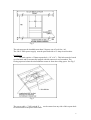
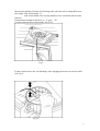
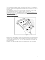
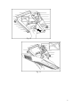
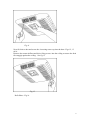
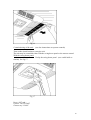
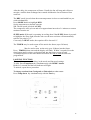
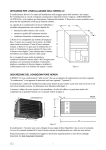
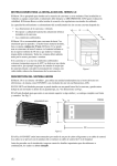
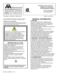
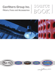
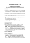
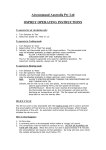
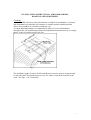
\
INSTALLATION INSTRUCTIONS AIRCOMMAND IBIS
ROOFTOP AIRCONDITIONER
Suitability:
The IBIS caravan rooftop aircondioner is suitable for installation on caravans
and motorhomes provided the roof structure is suitable and the installed position
allows for reasonable air circulation within the van.
A central installed position is recommended to allow for even air distribution
throughout the van. In difficult positions the airdistribution plenum may be set at right
angles to the fore/aft direction of the van
Fig 1
The installed weight of a unit is 46 KG and the roof structure must be strong enough
to carry this load. If in doubt always use an “H” frame to spread the load out to the
walls. See Figs. 1 & 2 for details.
1
Fig 2
The unit must not be installed more than 5 degrees out of level fore / aft.
The 240 V 50Hz power supply must be protected with a 15 Amp circuit breaker.
Installation:
The unit requires a 356mm square hole (14” x 14” ). This hole must be boxed
up all around and be structurally integral with the transverse roof members. The
boxing up must isolate the airconditioner return air from the ceiling space. See Fig.3
Fig 3
The power cable ( 7/050 twin & E )
can be entered on any side of this square hole
for connection to the power inlet block.
2
Before installing the unit over the square hole, clean the roof around the hole
to remove any grease etc. See Fig 4.
Fig 4
Take the sealing gasket and strip off the backing to expose the self adhesive side.
Lay the gasket over the hole and press down firmly.
Apply silicone sealant around the outside edge of the gasket, and now the
aircondioner is ready for installation over the hole. See fig . 5
Lift the unit over the hole and manipulate it so the hold down bolt holes are
sighted in each corner of the square hole.
Fig 5
3
Bolting down:
NB: The maximum length of threaded rod allowable to be screwed into the unit
is 60mm.
The standard rods supplied are 100mm x 5/16” BSW. If the ceiling thickness is such
that more than 60 mm will enter the unit, then the threaded rods must be shortened or
replaced with a shorter type.
Using an overlength rod may damage the evaporator assy within the unit.
Installing the 4 clamp bars: See Figs 6 &7
Firstly engage the 4 threaded rods into the moulded in nuts in the base of the unit. Run
the threaded rods in until there is about 20mm of rods below the ceiling line.
Now take each clamp bar in turn , feed them onto the threaded rod and force the
threaded rod firmly into the corner of the square hole.
Now using the nails provided, affix the clamp bars at 45 degrees across the corners of
the square hole. THIS IS MOST IMPORTANT.
Ensure that the heavy washers provided are used.
Now start the nuts and tighten each progressively to pull the unit down firmly.
Put on the second nut and lock it against the first to secure the bolts. Fig 6
Fig 6
4
Fig 7
Connection of power supply: See Fig. 8
The power cable can now be connected via the terminal block located on the
underside of unit.
Fig 8
Attachment of the duct assy & extension duct:
5
Measure the distance from the fan discharge tube, after the unit is clamped down to
the ceiling. This is dimension “A”
Add 15mm which is the overlap distance of the extension duct over the
fan tube.
Extension duct length is therefore A + 15 mm = “D”
Cut the extension duct to this length. See Fig 9
Fig 9
Fit the circular duct to the fan discharge tube engaging the notch over the fan cable.
See Fig 10
Fig 10
6
Now the duct can be engaged with the extension duct and pushed up firmly against
the ceiling. NB the extension duct should fit snuggly into the foam seal at the base of
the duct spigot.
Note that there are two sets of holes provided in the duct to secure it to the ceiling.
Select the holes that will pick up the timber framing around the hole.
Using the screws provided, screw the duct to the ceiling ensuring that the duct faces
fore and aft accurately. ( in some circumstances you may elect to install the duct at
right angles to fore and aft)
Installation of the plenum facia:
Fig 11
Firstly reach up and undo the tie securing the control cable. Let the control cable hang
down. See Fig 11 Minimise the amount of control cable hanging down by rolling it
up and securing with a rubber band. Too much cable laying about may interfere with
the removable filter.
Lift up the facia and connect the control cables together via the 4 pin micro plug.
7
Fig 12
Fig 13
8
Fig 14
Now fit facia to duct and screw the 4 securing screws up into the duct. Figs 12 , 13
& 14.
Remove the return airfilters and drive fixing screws into the ceiling to ensure the facia
fits snuggly against the ceiling. See fig 15
Fig 15
Refit filters. Fig 16
9
Fig 16
Commissioning of the unit: (see also instructions to operate controls)
Turn on the circuit breaker to energise unit.
The unit may be controlled either with the swing down panel or the remote control.
With the swing down panel:
Unclip the swing down panel . (use a table knife or
similar) See fig 17.
Fig 17
Press “ON” pad.
Choose “AUTO FAN”
Choose say “COOL”
10
Set temperature a few degrees below room temperature. Note: The digital readout =
actual room temp. Press down or up arrow the readout will blink out the set point and
then return to room temp.
The fan will start immediately and the compressor will start after a 3 minute delay.
Check unit runs OK and cools.
OPERATING INSTRUCTIONS
Turn the unit on by pressing the ON /OFF button once
Press the MODE button to cycle through options Cool, Dry, Heat , and Fan.
To select cooling, cycle mode button to highlight COOL.
You may select either High, Med, Low, or Auto fan speeds by pressing the FAN
button. It is recommended that you choose Auto.
Now select the desired room temperature (herein refereed to as SETPOINT).
By pressing the TEMP up or down keys, the readout will flash the setpoint
temperature. Keep pressing the button until it flashes your desired setpoint.
In approx 5 seconds the display will resume reading the actual roomtemp.
The compressor will have a delayed start usually 3 minutes, before unit starts to cool.
NB: Any interruption to the power supply will cause the unit to delay compressor start
up.
For simply recirculating air, choose the FAN mode.
Choose any of the three fan speeds by pressing FAN button.
NB: Temperature button is invalid in Fan only mode.
To heat, press MODE button to highlight HEAT.
Select desired setpoint temperature by pressing TEMP buttons up or down.
It is recommended that AUTO fan speed be selected.
11
After the delay, the compressor will start. Usually the fan will stop and will not re
energize until the heat exchanger has warmed and then the fan will start to blow
warm air.
The DRY mode is used when the room temperature is close to comfortable but you
wish to dehumidify.
Press MODE button to highlight DRY.
Set the temperature to desired setpoint.
NB: The fan speed is locked in LOW.
The compressor will cycle on and off at approximate intervals of 6 minutes to extract
moisture from the air.
SLEEP mode: If the unit is operating in cooling, then if the SLEEP button is pressed
to highlight the Sleep light, then the unit over the next one hour will automatically
raise the set point by 1C.
Conversely in HEAT mode, the setpoint will be lowered 1C.
The TIMER may be used to turn off the unit in the future (up to 24 hours)
Or
May be used to turn on the unit up to 24 hours into the future.
Press TIMER button once and the display will flash. Within 3 seconds ,Press the
timer button until you have set desired time into the future to turn off unit.
A subsequent press of the timer button will allow the time to start the unit to be
programmed.
LOCKING FUNCTION:
This provides a means of locking in the mode and fan speed settings.
To lock. Press Temp down key simultaneously with MODE button.
Hold for 3 seconds and the lock indicator will light.
To unlock, repeat above procedure.
To change readout from Centigrade to Fahrenheit or vice versa:
Press Temp down key simultaneously with the Fan key.
12
OPERATION USING THE REMOTE HANDPIECE:
Be sure to point the signal transmitter at the main control on the plenum.
All functions are available as per the main control.
Indicator lights will confirm what functions have been selected
13