1
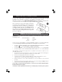
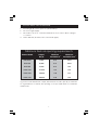
GAS HEATERS
Model Nos:
Little Devil • Devil 850 • Devil 1250 • Devil 1850 • Devil 3150
OPERATING & MAINTENANCE
INSTRUCTIONS
0802
Should you experience difficulty in setting
up or operating this equipment, please
contact your Clarke dealer, or Clarke
International helpline on:
020 8588 7400
For Spare Parts and Service, please contact your nearest dealer,
or CLARKE International, on one of the following numbers.
PARTS & SERVICE TEL: 020 8988 7400
PARTS & SERVICE FAX: 020 8558 3622
or e-mail as follows:
PARTS: [email protected]
2
Thank you for purchasing this CLARKE Gas Space Heater.
This range of portable, direct fired gas heaters is designed to BS 4096 for industrial
applications to give safe, efficient and reliable operation, and are for use with
Propane Gas only. Propane gas bottles are not supplied with the unit, but are
readily available from Builders Merchants or gas suppliers.
As with all mechanical equipments, optimum performance will only be achieved
if the correct application and servicing procedures are followed.
Please read this leaflet thoroughly and follow the instructions carefully before
attempting to use the heater. In doing so you will ensure the safety of yourself
and that of others around you, and you can look forward to it giving you long
and reliable service.
GUARANTEE
This CLARKE product is guaranteed against faulty manufacture for a period
of 12 months from the date of purchase. Please keep your receipt as proof
of purchase.
This guarantee is invalid if the product is found to have been abused or
tampered with in any way, or not used for the purpose for which it was
intended.
Faulty goods should be returned to their place of purchase, no product
can be returned to us without prior permission.
This guarantee does not effect your statutory rights.
CONTENTS
PAGE
Safety Precautions ............................................................................ 4
Electrical Connections ...................................................................... 5
Gas Connection ................................................................................ 6
Changing Gas Bottles ....................................................................... 6
Operation ........................................................................................... 7
Starting Procedure ............................................................................ 8
Stopping Procedure .......................................................................... 9
Fresh Air Requirements ...................................................................... 9
Maintenance ..................................................................................... 10
Specifications ..................................................................................... 10
Trouble Shooting ................................................................................ 11
Wiring Diagrams ................................................................................. 12-13
Parts Lists and Diagrams ................................................................... 14-23
3
SAFETY PRECAUTIONS
WARNING!
Lack of ventilation can cause Carbon Monoxide poisoning.
Carbon Monoxide poisoning can kill.
Signs of Carbon Monoxide poisoning are, headaches, dizziness and/or nausea. Should
anyone show these signs, they must GET FRESH AIR IMMEDIATELY. Turn off the heater and
have it serviced before using again.
Pregnant women, persons with a heart or lung condition, anaemia or under the influence
of alcohol, or those at high altitudes, are more likely to be effected by Carbon Monoxide
than others.
Read, and make sure you fully understand the following precautions and the hazards
associated with this type of equipment.
•
Use ONLY Propane gas
•
Ensure the Propane gas bottle, gas hose and electric cable, are positioned behind
the unit, well away from the heat
•
Ensure all gas hose and regulator connections are GAS TIGHT, and the hose is not
kinked.
•
NEVER use the heater where Gasoline, Paint thinner or other highly flammable vapour
or high dust content is present.
•
Use ONLY with the electrical voltage specified, and ensure the appliance is properly
earthed.
•
Use ONLY in well ventilated areas. Provide ventilation of at least 100 square inches of
fresh air for every 100,000 BTU/ hr of rating.
•
The minimum clearance from any combustible materials is 8 feet (250cm) from hot
air outlet and 4 feet (125cm) from the top and sides.
•
Stand the heater on a stable, level surface whilst hot or operating. If the heater
should overturn, a fire could occur.
•
Keep children and animals away from heater at all times.
•
Use heater in accordance with all fire regulations.
•
NEVER use heater in living or sleeping areas.
•
NEVER leave a heater plugged in without adult supervision if children or animals are
likely to be present.
•
NEVER move, handle, replenish gas supply or service the heater, when it is hot,
operating or plugged in.
•
NEVER attach duct work, or impede air flow into or out of heater.
•
Disconnect the heater from the power supply when not in use.
•
Use ONLY the regulator supplied with the machine.
•
DO NOT exceed the limit of 240Btu/hr, per square metre of room area.
•
If the machine works for long periods at maximum capacity, be aware that it is possible
for ice to form on the cylinder, due to excessive evaporation.
•
NEVER direct hot air towards the cylinder in order to de-ice.
4
ELECTRICAL CONNECTIONS
Connect the mains lead to a standard, 230 Volt (50Hz) electrical supply through
an approved 13 amp BS 1363 plug, or a suitably fused isolator switch.
With the exception of the Little Devil and Devil 650, the appliance may also be
connected to a 110 Volt supply, through a suitably approved plug.
The conversion to 110V, is by means of a switch,
mounted on the rear panel of the unit, which is
held in place by a lock plate. To change the
voltage, remove the two self tapping screws
securing the plate, and remove the plate. Move
the switch to the appropriate position, and
replace the plate having turned it through 180O
as shown opposite.
Fig.1
WARNING! THIS APPLIANCE MUST BE EARTHED
IMPORTANT: The wires in the mains lead are coloured in accordance with the
following code:
Green & Yellow
Earth
Blue
-
Neutral
Brown
-
Live
As the colours of the flexible cord of this appliance may not correspond with the
coloured markings identifying terminals in your plug proceed as follows:
•
Connect GREEN & YELLOW cord to terminal marked with a letter “E” or Earth
symbol ‘
’ or coloured GREEN or GREEN & YELLOW.
•
Connect BROWN cord to terminal marked with a letter “L” or coloured RED
•
Connect BLUE cord to terminal marked with a letter “N” or coloured BLACK
If this appliance is fitted with a plug which is moulded onto the electric cable (i.e. nonrewirable) please note:
1.
The plug must be thrown away if it is cut from the electric cable. There is a danger of
electric shock if it is subsequently inserted into a socket outlet.
2.
Never use the plug without the fuse cover fitted.
3.
Should you wish to replace a detachable fuse carrier, ensure that the correct
replacement is used (as indicated by marking or colour code).
4.
Replacement fuse covers can be obtained from your local dealer or most electrical
stockists.
5.
The fuse in the plug must be replaced with one of the same rating (13 amps) and this
replacement must be ASTA approved to BS1362.
We strongly recommend that this machine is connected to the mains supply through a
Residual Current Device (RCD).
If in doubt, consult a qualified electrician. Do not attempt any electrical repairs yourself.
5
UNPACKING
On unpacking, check the heater for possible shipping damage. Should any
damage be apparent, please notify your Clarke dealer immediately.
Your heater is fully assembled, only the electrical and gas supply’s need
connecting.
PROPANE GAS SUPPLY
These heaters are designed for use with PROPANE gas ONLY. Gas bottles are not
WARNING
Propane Gas cylinders must be used and stored in accordance with the
‘Highly Flammable Liquids and Liquefied Petroleum Gases Regulations 1972’
supplied, but are readily available from Builders Merchants or gas suppliers etc
GAS CONNECTION
Connect the free end of the gas hose to the gas inlet connection on the machine, and
tighten to ensure there are no gas leaks. Before attaching the regulator to the gas cylinder,
ensure the mating parts are free from grease and dirt, and are undamaged.
Fit the regulator to the cylinder, tightening the thread as tight as possible with a
propane spanner, noting that the threads are LEFT HANDED. To check for leaks,
use soapy water, or liquid soap
IMPORTANT: The gas hose and cylinder must ALWAYS be located behind the
machine.
Fig.2
In order to reduce the risk of icing up
when operating at long periods at
maximum capacity, you should use a
larger capacity gas bottle, or two/three
bottles in parallel, as shown in Fig. 2.
The ‘Tee’ piece and ‘pigtails’ are
readily available from your Builders
Merchants or gas supplier
CHANGING GAS BOTTLES
1.
Turn off the heater, and disconnect from the electrical supply.
2.
Close the gas valve on the bottle, and unscrew the regulator, (left hand thread).
3.
Ensure the replacement bottle screw threads and gas orifice is perfectly
clean before screwing in the regulator valve, tightly.
4.
Check to ensure there are no leaks using soapy water, and when satisfied,
plug in to the electrical supply, and restart the machine.
6
OPERATION
Understanding the basic operation of the heater, will reinforce the need to
maintain the unit in top condition at all times, whilst always observing the safety
precautions.
The heater comprises four basic systems:
1.
The gas system.
2.
The air system.
3.
The ignition system.
4.
The safety control system.
1. Air System
An axial fan, which is energised when switching ON, provides the main air flow.
2. Gas System
The gas supply to the machine is by means of a high pressure hose, connected
to a LPG cylinder, via a pressure regulator.
When the mains supply is switched on, the Safety Shut-off Valve Solenoid is
energised, allowing the gas to flow to the Flame Failure Valve, and when the
Failure Valve Override knob is depressed, gas flows to the Burner Head.
3. Ignition System
A Piezoelectric Igniter is positioned at the burner head. When the Igniter button
is depressed, a high intensity spark is generated, which ignites the gas. Heat from
the flame is sensed by a Thermocouple, which is connected to the Flame Failure
Valve. As the Thermocouple heats up, a low voltage is fed to the Flame Failure
Valve, causing the valve to open, so that after 5-10 seconds, the Override knob
may be released, and the main flame is established.
4. The Safety Control System.
Should the flame extinguish for any reason, the Thermocouple will quickly cool,
causing the Flame Failure Valve to close, shutting off the gas supply.
Similarly, should there be a power failure, causing the fan motor to stop, the
Safety Shut-Off Valve Solenoid will become de-energised, and therefore shut off
the gas supply.
Additionally, the machine is fitted with Thermal Overload Protection, which will
intervene should the unit overheat, shutting off the electrical supply.
7
STARTING PROCEDURE
WARNING!
Before starting the heater, you MUST ensure that the minimum ventilation
requirements are observed, to avoid the risk of carbon monoxide poisoning.
1.
Ensuring there is sufficient gas, and that it is correctly connected, open the
valve on the gas cylinder, and open the regulator valve which is adjacent
to the gas inlet pipe. (Not applicable on the Little Devil).
2.
Plug the heater in to a suitably earthed supply, and observing all precautions
previously stated, push the fan switch to the ON (I) position, (1, Fig.3), and
ensure the fan operates.
3. Fully depress the gas valve button (2, Fig.3), which is adjacent to the gas
inlet pipe, and push the ignition button (3, Fig.3), repeatedly, until the burner
ignites. Keep the gas valve button (4, Fig.3), depressed for a further 10
seconds approx., until the main flame is established.
Should the flame extinguish when the gas valve button is released, wait for
1 minute, before repeating the operation, this time, holding down the gas
valve button for a longer period.
Fig.3
NOTES:
The Little Devil and Devil 650 heaters have a fixed, regulated gas flow, whereas
all other models have a variable gas flow regulator so that you can regulate the
heat output by adjusting the regulator pressure.
Turning the knob clockwise will increase the pressure, and therefore the output,
anticlockwise to decrease.
If ignition is difficult or irregular, ensure the fan is operating, and that the air inlet
and outlet are completely free. Ensure also that the electrode gap is correct,
and that the electrode is clean (see Maintenance).
IMPORTANT:
Should the thermal overload protection feature operate, shut off the gas
supply, and allow the unit to cool for at least 10 minutes, with the fan running,
before attempting to relight the burner.
Should the other safety features (previously mentioned) operate, the heater
may be restarted once the cause of the problem has been found and rectified.
8
STOPPING PROCEDURE
1.
Turn OFF gas at source. (Turn off cylinder valve).
2.
Disconnect gas supply.
3.
Allow fan to run for 2 - 3 minutes with burner off, in order to allow casing to
cool down.
4.
Switch OFF fan, and disconnect electrical supply.
Minimum fresh air opening requirements
Heater Model
Output
Btu/hr
Minimum
Ventilation ft2
Minimum
Ventilation mtrs2
Little Devil
34,000
0.25
0.023
Devil 650
60,000
0.36
0.035
Devil 850
78,500
0.75
0.07
Devil 1250
121,000
1.03
0.10
Devil 1850
170,000
1.40
0.13
Devil 3150
300,000
2.40
0.22
eg. For the Devil 1250 at max. output, a 3ft window must be open by 13" minimum
As a general rule of thumb, an opening of 1in2 per 1000 Btu/hr is a minimum
requirement.
9
MAINTENANCE
It is essential that the heater is correctly maintained and kept in top condition at all times.
IMPORTANT
Before carrying out any adjustment or maintenance, ensure the heater is
switched OFF, disconnected from the mains and gas supply’s, and has been
given adequate time to cool down.
All models are similar, in that access to the working parts, is gained by removing
the rear panel, which is secured by 4 screws, (3 in the case of the Little Devil),
around its’ edge. Once removed, the panel complete with all components may
be lifted clear.
Monthly (When in constant use)
Ensure the electrode is clean, and the gap is no more than 5mm (see fig 4).
Check the condition of the gas hose, if there are any signs of deterioration, it
should be renewed, using only a CLARKE original spare part.
Ensure that all connections are clean and firm.
When necessary, clean the fan and inside of the heater thoroughly.
SPECIFICATIONS
Little
Devil
Devil
650
Devil
850
Devil
1250
-
24,000
60,500
83,350
198,000
34,000
60,000
78,500
121,000
170,000
300,000
0.3/5
0.7/10
1.5/22
1.5/22
1.5/22
2/30
Air Flow (m3/hr)
300
300
650
650
1,500
3300
Gas Consumption (kg/hr)
0.8
1.35
0.6 - 1.8
1.4 - 2.8
2-4
4.6 - 8.3
Nozzle Size (mm)
0.7
1.00
1.1
1.25
1.5
2.0
Min. Output (Btu/hr)
Max. Output (Btu/hr)
Gas Pressure Max (bar/psi)
Motor Voltage (Volts)
Power rating (Watts)
Input Current 230V (Amps)
-
230 -1ph 230 -1ph 110/230-1ph 230 -1ph 230 -1ph
35
35
0.26
0.3
110V (Amps)
Fuse Rating (Amps)
Dimensions (mm)
Weight (kg)
Part No.
Devil
1850
Devil
3150
230 -1ph
85
85
91
140
0.7
0.35
0.42
0.5
13
13
13
0.3
13
13
13
350x180x270 490x180x270 550x270x320 635x270x380 725x460x535 1075x420x565
5
6
13
15.5
23
30
6920160
6920162
6920170
6920340
6920360
6920350
10
TROUBLE SHOOTING
FAULT
Motor does not start
CAUSE
REMEDY
1. Check power supply, power
1. No power
cable and fuse, and replace if
necessary.
2. Faulty Motor/
Capacitor
2. Check and if necessary,
replace.
3. Lock out of appliance
due to overheating.
3. Detect cause of overheating.
Wait for 5 mins, and restart. If
condition persists, contact
your Clarke dealer for advice.
1. Electrode in wrong
position
1. Check position and reset if
necessary.
2. Faulty connection
between Piezo and
electrode.
2. Check, and connect
properly.
1. Cylinder gas tap closed.
1. Open the gas tap.
2. Cylinder is empty.
2. Replace cylinder.
3. The nozzle is obstructed.
3. Remove the nozzle, and
clean it.
4. Gas leaks from the
supply hose or from
the tap.
4. Use soapy water to find the
leak, and repair.
The burner starts, but
stops as gas valve is
released.
1. The thermocouple is
not warm enough.
1. Repeat the starting operation,
keeping the gas valve button
depressed for a longer time.
The Heater stops
during operation.
1. Excessive gas supply.
1. Check the pressure regulator,
and replace if necessary.
Piezo does not spark
No gas flow to the
burner
2. Check that fan motor works
properly.
3. Check, and use a larger
cylinder, or two or more in
parallel.
4. Investigate cause, check to
ensure there are no obstructions
to air flow. Check adequate
ventilation is provided. See also
‘Motor does not Start’
11
WIRING DIAGRAMS
IMPORTANT: The wiring to these heaters should not be tampered with under
any circumstances. Should any wiring problems occur, contact your nearest
CLARKE dealer or qualified electrician.
Little Devil, Devil 650 & Devil 850
F1
Safety Thermostat
M1
Fan Motor
Q1
Switch
Q2
Piezoelectric Ignition
S1
Thermocouple
S2
Ignition Electrode
S3
Gas Valve
X1
Terminal Board
S4
Solenoid Valve
Devil 1250
B1
Safety Thermostat
G1
Gas Valve
M1
Fan Motor
Q1
Switch
Q2
Piezoelectric device
S1
Ignition Electrode
S2
Thermocouple
Y1
Solenoid Valve
12
Devil 1850
B1
Safety Thermostat
C1 Capacitor
G1 Gas Valve
M1 Fan Motor
Q1 Switch
Q2 Piezoelectric device
S1
Starting Electrode
S2
Thermocouple
Y1
Solenoid Valve
X1 Terminal Board
Devil 3150
B1
Safety Thermostat
B2
Room (External) Thermostat
F1
Fuse
M1 Fan Motor
Q1 Switch
S1
Ionisation Probe
S2
Starting Electrode
Y1
Solenoid Valve
X1 Terminal Board
13
LITTLE DEVIL
14
LITTLE DEVIL
No. Description
Part No.
No. Description
Part No.
1
Chamber
2003104255
28
Terminal Board
1005064500
2
Rivet
1004043000
29
Switch
1005092855
3
Handle
1001015755
30
Label
1004010955
4
Aluminium Rivet
1004014800
31
Grommet
1005091455
5
Cone + Triangle
2003103655
32
Screw
1004012300
7
Washer
1004001100
33
Support
2003059855
8
Body
2003104055
35
Cable
1005091600
9
Grille
1008079955
36
Nozzle
1008063955
10
Motor
1005061300
37
Fitting
1006020555
11
Fan
1008063655
38
Solenoid Valve
1005069200
12
Coupling
1001017855
39
Valve
1006013355
13
Wire
2005054155
40
Fitting
1006017955
14
Screw
1004014000
42
Nut
1006013400
15
Electrode
1005082755
43
Screw
1004011600
16
Disc
2003060155
44
Wire
2005054455
17
Screw
1004000100
45
Blue Wire
2005054555
18
Thermostat
1005062300
45
Brown Wire
2005054655
20
Burner
1008079755
45
Earth Wire
2005054755
21
Thermocouple
1006018355
46
Hose
1009010255
23
Wire
2005054255
47
Valve
1008060755
24
Fastening Ring
1004013100
48
Pressure Regulator 1008072455
25
Piezo Igniter
1005061200
49
Cover Cap
1005092955
26
Rubber Ring
1001005100
50
Fitting
1006014900
15
DEVIL 850
16
DEVIL 850
No. Description
Part No.
No. Description
Part No.
1
Chamber
2003103855
29 Electrode
1005063500
2
Body
2003099855
30 Wire
2005048355
3
Handle
1001014700
31 Wire
2005071655
4
Rivet
1004043000
32 Rivet
1004043100
5
Washer
1004001100
33 Burner
1008065655
6
Aluminium Rivet
1004043600
34 Disc
2003104455
7
Grille
1008078455
35 Fitting
1006026455
8
Support
2003091355
36 Washer
1006003500
9
Screw
1004012600
37 Fitting
1006020755
10 Hose
1009010355
38 Fan
1008058700
11 Valve
1008094055
39 Coupling
1001017855
12 Pressure Regulator
1008094355
40 Motor
1005079155
13 Adapter
1006014900
41 Air Conveyor
2003099555
14 Cover
1001038255
42 Black Cap
1005076000
15 Connector
2005076855
43 Piezo Igniter
1005061200
16 Fitting
1006004100
44 Cable
1005102455
17 Hose
2009009555
45 Screw
1004011600
18 Nut
1006018055
46 Fair Lead
1005081755
19 Olive
1006018055
47 Cap Cover
1005092600
20 Valve
1006015355
48 Switch
1005092500
21 Fitting
1006026555
49 Rubber Ring
1001005100
22 Fitting
1006020400
50 Fitting
1006020555
23 Hose
2002019555
51 Solenoid Valve
1005069200
24 Thermocouple
1006018355
52 Nozzle
1008065755
25 Thermostat
1005087800
53 Nut
1006013400
26 Screw
1004000100
54 Tap
1008095455
27 Circlip
1004013100
55 Fitting
1006026655
28 Disc
2003099655
17
DEVIL1250
18
DEVIL1250
No. Description
Part No.
No. Description
Part No.
1
Chamber
2003128455
29 Electrode
1005082836
2
Body
2003128355
30 Wire
2005048355
3
Handle
1001014700
31 Wire
2005071655
4
Rivet
1004043000
32 Rivet
1004043100
5
Washer
1004001100
33 Burner
1008094655
6
Rivet
1004043600
34 Disc
2003104455
7
Grille
1008078455
35 Fitting
1006026455
8
Support
2003091355
36 Washer
1006003500
9
Screw
1004012600
37 Fitting
1006020755
10 Hose
1009016055
38 Fan
1008058700
11 Valve
1008094055
39 Coupling
1001017855
12 Pressure Regulator
1008094355
40 Motor
1005079155
13 Adapter
1006014900
41 Air Conveyor
2003099555
14 Cover
1001038255
42 Black Cap
1005076000
15 Connector
2005076855
43 Piezo Igniter
1005061200
16 Fitting
1006004100
44 Cable
10051402455
17 Hose
2009009555
45 Screw
1004011600
18 Nut
1006014100
46 Fair Lead
1005081755
19 Olive
100601055
47 Cover
1005092600
20 Valve
1006015355
48 Cap
1005092500
21 Fitting
1006026555
49 Rubber Ring
1001005100
22 Fitting
1006020400
50 Fitting
1006020555
23 Hose
2002019555
51 Solenoid Valve
1005069200
24 Thermocouple
1006018355
52 Nozzle
1008094255
25 Thermostat
1005087800
53 Nut
1006013400
26 Screw
1004000100
54 Tap
1008096055
27 Washer
1004013100
55 Fitting
1006026655
28 Disc
2003099655
19
DEVIL1850
20
DEVIL1850
No. Description
Part No.
No. Description
Part No.
1
Chamber
2003072636
27 Wire
2005048355
2
Handle
1001018636
28 Nut
1006016000
3
Body
2003072436
29 Burner
1008071836
4
Grille
1008071736
30 Fitting
1006026555
5
Foot
2003072536
31 Fitting
1006026455
6
Nut
1004013600
32 Disc
2003105336
7
Cap
1001010900
33 Electrode
1005082836
8
Hose
1009010355
34 Nozzle
1008071936
9
Valve
1008095836
35 Disc
2003104455
10 Pressure Regulator 1008094355
36 Fitting
1006015955
11 Adapter
1006014900
37 Thermostat
1005087800
12 Cover
1001038736
38 Nut
1005001121
13 Terminal Board
1005070155
39 Air Conveyor
2003072736
14 Insulator
1014057936
40 Rubber Ring
1001005100
15 Capacitor
1005076236
41 Cap
1001019900
16 Tap
1008095536
42 Piezo Igniter
1005061200
17 Nut
1006026755
43 Fair Lead
1005001021
18 Fitting
1006026655
44 Cable
1005102536
19 Valve
1006015355
45 Washer
1004004400
20 Connector
2005077636
46 Screw
1004005000
21 Fitting
1006004100
47 Grille
10080781636
22 Fitting
1006020400
48 Motor- Fan
1005076136
23 Hose
2002016736
49 Cover Cap
1005092600
24 Solenoid Valve
1005069200
50 Switch
1005092500
25 Thermocouple
1006018355
51 Fitting
1006020755
26 Hose
2002019555
21
DEVIL3150
22
DEVIL3150
No. Description
Part No.
No. Description
Part No.
1
Chamber
2003119036
27 Wire
2005073336
2
Body
2003118836
28 Wire
2005073436
3
Grille
1008071736
29 Nut
1006026755
4
Cap
1001018800
30 Nozzle
1008087736
5
Washer
1004010900
31 Fitting
1006021055
6
Wheel
1001002000
32 Air Conveyor
2003118936
7
Foot
2002019036
33 Thermostat
1005087800
8
Hose
1009010355
35 Nut
1005001121
9
Valve
1008095836
36 Push Button
1005082055
10 Pressure Regulator
1008095736
37 Cover Cap
1005099855
11 Adapter
1006014900
38 Fair Lead
1005001021
12 Cover
1001038836
39 Cable
1005012536
13 Flame Control
1005081855
40 Rubber Ring
1001005100
14 Rivet
1004005300
41 Cover
1001038736
15 Stirrup
2003128736
42 Motor
1005011732
16 Tap
1008095636
43 Connector
1005061800
17 Fitting
1006027755
44 Screw
1004002900
18 Fitting
1006001600
45 Connector
1005061600
19 Connector
2005077736
46 Cover
1005078600
20 Solenoid Valve
1005069200
47 Handle
2002019436
21 Fitting
1006004100
48 Grille
1008088236
22 Fitting
1006020400
49 Fan
1008088136
23 Hose
2002021336
50 Capacitor
1005076236
24 Burner
1008087636
51 Fuse Carrier
1005099600
25 Disc
2003117436
52 Fuse
1005002700
26 Electrode
1005082836
53 Cover Cap
1005092600
27 Wire
2005073336
54 Switch
1005092700
28 Wire
2005073436
55 Fitting
1006020755
29 Nut
1006026755
56 Washer
1006003500
23 Hose
2002021336
57 Terminal Board
1005070155
24 Burner
1008087636
58 Insulator
1014057336
25 Disc
2003117436
59 Fitting
1006015000
26 Electrode
1005082836
23