1
Streamline FS Condensing Boiler
Operating & Maintenance Manual
For Models 150 & 225
MHS Boilers Ltd
3 Juniper West
Fenton Way
Southfields Business Park
Basildon
Essex
SS15 6SJ
01268 546700 Telephone 01268 888270 Fax
WWW.MHSBOILERS.COM
L293
© MHS Boilers Ltd
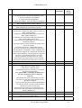
Contents.
Appliance Type
Standalone
Cascade Manager
Cascade Slave
Installation Regulations and Requirements
Dimensions
Installation Clearances
Delivery and Mobility
Technical Data
Pressure Relief Valve
Electrical Connections
Hydraulic Design
Standalone
Control Wiring
Standalone
Hydraulic Design
Cascade
Control Wiring
Cascade
Fluing Options
Standalone Conventional Flue
Standalone Balanced Flue
Cascade Conventional Flue
Cascade Balanced Flue
Filling The System
Pressure Vessel
System Water Quality
Care With The Use Of Solder Flux
Appliance Controls
Control Panel
RVA47 Cascade Manager
Module Controller
Module Controller End User Settings
Appliance Error Codes
Controller Parameter Default Settings
RVA47 Cascade Manager
Module LMU64 Controller (QAA73 Unit Required.)
Commissioning
Pre-Commissioning Checks.
Combustion System Commissioning
Internal Wiring
Module Control Indication
Internal Wiring Diagram
Exploded Diagrams
Spares Listings
Installer / End Users Note
221106 Draft Copy E&OE
2
© MHS Boilers Ltd
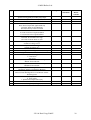
Appliance Type.
There are three build types within the Streamline FS range.
Please ensure you have the correct unit for the application and where required located
correctly within the cascade prior to beginning the installation.
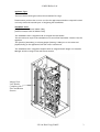
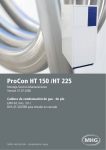
Standalone Units.
(150 FS Product Code 96.30000-7134)
(225 FS Product Code 96.30000-7135)
The Standalone Unit is supplied with an integral low loss header.
This unit does not require the installation of a second low loss header remote from the
appliance.
The system’s (Secondary) circulating pumps (Heating / HWS) are to be connected
(hydraulically) to the appliances flow and return connections.
The Standalone Unit is supplied complete with an integral RVA47 Single Unit Cascade
Manager wired to integral flow and return sensors.
Integral Low
Loss Header.
Complete with
Flow and Return
Sensors
221106 Draft Copy E&OE
3
© MHS Boilers Ltd
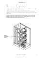
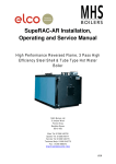
Cascade Manager Units
(150 FS Product Code 96.30000-7136)
(225 FS Product Code 96.30000-7137)
The Cascade Manager Unit is supplied without an integral low loss header.
A suitably sized low loss header must be installed within the system.
The system’s (Secondary) circulating pumps (Heating / HWS) are to be connected
(hydraulically) to the external low loss header and not to the appliances flow and return
connections.
The Cascade Manager Unit is supplied complete with an integral RVA47 multiple unit
Cascade Manager. Remote Flow and Return sensors (QAD21) must be mounted as
indicated in the hydraulic diagram section of manual and wired back the unit.
Integral
Distribution
Header.
221106 Draft Copy E&OE
4
© MHS Boilers Ltd
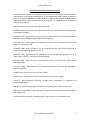
Cascade Slave Units.
(150 FS Product Code 96.30000-7138)
(225 FS Product Code 96.30000-7139)
The Cascade Slave Unit is supplied without an integral low loss header and should only
installed where a Cascade Master is also installed
A suitably sized low loss header must be installed within the system.
The system’s (Secondary) circulating pumps (Heating / HWS) are to be connected
(hydraulically) to the external low loss header and not to the appliances flow and return
connections.
The Cascade Slave Unit is supplied without an integral RVA47 multiple unit Cascade
Manager and therefore relies on the presence of a Cascade Master Unit to provide
operational signals via the LPB communication wiring.
Integral
Distribution
Header.
221106 Draft Copy E&OE
5
© MHS Boilers Ltd
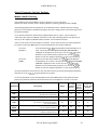
Installation Regulations and Requirements
The installation of Strata Streamline FS boilers must be in accordance with the relevant
requirements of Gas Safety (Installation & Use) Regulations 1994, Health & Safety at
Work Act, Building Regulations, IEE Regulations, Construction (Design & Management)
Regulations 1994, Local Authority Bye-Laws, National, Fire Regulations and Insurance
Company requirements.
The following Codes of Practice are also applicable:BS 5449: 1990 Specification for forced circulation hot water central heating systems
for domestic premises.
BS 6644: 2005 Specification for gas fired hot water boilers of rated inputs between
70kW (net) and 1.8MW(net) (2nd and 3rd family gases).
BS 6798: 1987 Specification for installation of gas fired hot water boilers of rated
input not exceeding 60 kW.
BS 6880: 1988 Code of Practice for low temperature hot water heating systems of
output greater than 45kW. Parts 1, 2 & 3.
BS 6891: 1988 Specification for installation of low pressure gas pipework of up to
28mm (R1) in domestic premises (2nd family gases)
BS 7593: 1992 Code of Practice for treatment of water in domestic hot water central
heating systems.
BS 7671: 1992 Requirements for electrical installations. IEE Wiring Regulations.
Sixteenth edition.
CISBE Guide reference sections B7, B11 and B13.
CP342 Part 2: 1974 Code of Practice for centralized hot water supply.
GE/UP/2 Gas installation pipework, boosters and compressors on industrial and
commercial premises.
IGE/UP/4 Commissioning of gas fired plant on industrial and commercial premises
IGE/UP/10 Installation of gas appliances in industrial and commercial premises. Part 1:
Flued appliances.
And any addition prevailing regulation and or code of practice not detailed above.
221106 Draft Copy E&OE
6
© MHS Boilers Ltd
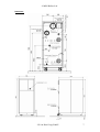
Dimensions.
221106 Draft Copy E&OE
7
© MHS Boilers Ltd
Installation / Service Clearances
Dimension
[Minimum mm Clearance ]
A
B
C
D
E
500
1000
700
680
1050
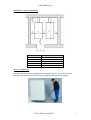
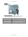
Delivery And Mobility.
Each Streamline FS boiler is supplied with a manoeuvring tool. This is to be used to
facilitate the correct position of the unit. (Shipped within the boiler casing.)
221106 Draft Copy E&OE
8
© MHS Boilers Ltd
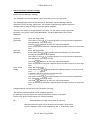
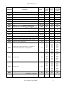
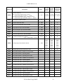
Technical Data
Technical Data
Nominal Heat Input Net
Min/Max
Nominal Heat Output
Min/Max
(50ºC/30ºC)
Nominal Heat Output
Min/Max
(80ºC/60ºC)
Design Water Flow Rate
Residual Head from In-built
Pumps (Cascade version
only)
Maximum Input Gas Rate
G20
G31
Gas Inlet Pressure
Min/Max
Maximum Flue Gas Mass
G20 (Hot)
Maximum Flue Gas Mass
G31 (Hot)
Residual Fan Pressure
Maximum Water Pressure
(Hot)
Minimum Water Pressure
(Cold)
Maximum Flow Temperature
Power Supply (240 V / 50
Hz)
Max Power Consumption
Water Content
Lift Weight (Dry)
Lift Weight (Wet)
Efficiency @ Full Load
Gross
Efficiency @ 30% of Full
Load Gross
NOx emission @ 0% O2
150
225
kW
15.0/149.2
15.0/216.0
kW
16.0/155.0
16.0/225.0
kW
14.5/143.2
14.5/206.0
Ltr/sec
1.8
2.66
kPa
15.0
15.0
m³/hr
m³/hr
mbar
Kg/hr
Kg/hr
Pa
bar
bar
ºC
Amps
15.0
5.77
18.0/50.0
250.9
231.4
200
3.0
1.0
90
7
21.7
8.35
18.0/50.0
363.6
335.1
200
3.0
1.0
90
7
Watts
Ltrs
kg
kg
%
690
30
250
280
86.48
800
35
270
305
85.67
%
98.20
98.37
Mg/kW
h
Flue Classification
26.7 (Class 5)
B23, C33, C43, C53, C63, C83.
Connections
HTG Primary Flow
HTG Primary Return
Gas
Flue Connection
Combustion Air Connection
Condensate Outlet
PN6
PN6
BSP
Plastic
DN 40
DN 40
R1.25”
DN 160
DN 125
20mm
DN 40
DN 40
R1.25”
DN 160
DN 125
20mm
Please note that the condensate disposal system must be installed in Plastic or Stainless
Steel. (Copper is not acceptable.)
221106 Draft Copy E&OE
9
© MHS Boilers Ltd
Pressure (Safety) Relief Valve
In accordance with BS 6644: 2005, the installer shall install as suitably sized Pressure
(Safety) Relief Valve.
The location of this valve is important with respect to the applied pressure of the boiler
circulation pump, it is therefore recommended to locate the Pressure (Safety) Relief
Valve on the flow pipe immediately adjacent to the boiler; furthermore, there must not
be any means of isolation between the boiler and the Pressure (Safety) Relief Valve.
Electrical Connections
Basic electrical connection for all type of Streamline FS
Additional terminals requiring Field Wiring for Cascade Manager Streamline FS units
Only
(These terminals are prewired on Standalone Streamline FS units.)
221106 Draft Copy E&OE
10
© MHS Boilers Ltd
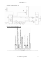
Hydraulic Design Standalone Unit
Electrical Connections Standalone Unit
If Direct On Boiler Weather Compensation is not required a 620 Ohm Resistor must be applied to the AF terminals to remove the E10 Error Code from the RVA47 Cascade
Manager LPB Network.
221106 Draft Copy E&OE
11
© MHS Boilers Ltd
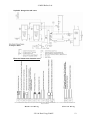
Hydraulic Design Cascade Units
Electrical Connections Cascade Units
If Direct On Boiler Weather Compensation is not required a 620 Ohm Resistor must be applied to the AF terminals to remove the E10 Error Code from the RVA47 Cascade
Manager LPB Network.
Master Unit Wiring
221106 Draft Copy E&OE
Slave Unit Wiring
12
© MHS Boilers Ltd
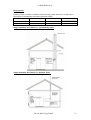
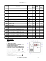
Fluing Options
Please not that excessive resistance within the flue system will lead to a reduction in
the output of the appliance and induce operation faults.
Boiler Type
Flue Outlet Size
Flue Size
Maximum Length
Flue and Combustion Air Ducts Combined
Streamline 150
Streamline 225
DN 160
DN 160
DN 160
DN 160
28m
23m
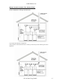
Single Standalone Streamline FS. Conventionally Flued.
Single Standalone Streamline FS. Balanced Flued.
221106 Draft Copy E&OE
13
© MHS Boilers Ltd
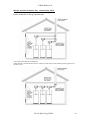
Multiple Cascade Streamline FS’s. Conventionally Flued.
Preferred Method of Fluing Cascaded units
Conventional Flue Header Arrangement.
If this method is utilised the flue must be sized to prevent back pressure effecting other appliances on
the flue system.
221106 Draft Copy E&OE
14
© MHS Boilers Ltd
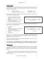
Multiple Cascade Streamline FS’s. Balanced Flued.
Preferred Method of Fluing Cascaded units
Conventional Flue Header Arrangement.
If this method is utilised the flue must be sized to prevent back pressure effecting associated
appliances.
221106 Draft Copy E&OE
15
© MHS Boilers Ltd
Filling The System
The Initial filling of a sealed heating system, and subsequent refilling, must be by a
method that has been approved by the Water Regulation Advisory Scheme (WRAS) for
that type of heating system.
i.e.
Domestic (In-House)
Non Domestic (Other than In-House)
Fluid Category 3 (C-3)
Fluid Category 4 (C-4)
For Category 3 systems, the approved method of filling must comprise of the following
components in the arrangement shown;
•
•
•
Control Valve incorporating a Double
Check Valve on the Mains Cold Water
pipework.
Temporary Connecting Hose, which must
be disconnected after use.
Control Valve, on the heating system.
For Category 4 systems, the approved method of filling must comprise of the following
components in the arrangement shown;
•
•
•
•
•
•
Control Valve.
Strainer.
Verifiable Backflow Device with Reduced
Pressure Zone (RPZ Valve)
Incorporating a ‘Type BA’ Air Gap.
Tundish.
Control Valve.
Further more, in accordance with BS 6644: 2005 system with an input greater than
70kW (nett), an automatic water replenishment unit shall be installed to automatically
replenish any lost or evaporated water.
Please refer to BS 6644: 2005 for allowable water replenishment methods for use with
sealed/pressurized heating systems.
For information on a comprehensive range of pressurization units that comply with
current British Standards and WRAS Regulations, please contact MHS Boiler Sales.
Expansion Vessel
In accordance with BS 6644: 2005, WRAS Regulations, and Local Authority Water
Regulations, as applicable, the installer shall install a suitably sized, and approved,
Expansion Vessel to ensure that the water capacity of the system has ample expansion
capacity.
The location of the expansion vessel shall only be isolatable from the system via a
Lockable Type Service Valve, which shall be locked in the OPEN position, to prevent
accidental isolation.
221106 Draft Copy E&OE
16
© MHS Boilers Ltd
Furthermore, a drain facility should be provided adjacent to the expansion vessel
to aide the routine maintenance, overhaul, of the vessels Air Pressure setting.
For information on a comprehensive range of expansion vessels that comply with
current British Standards and WRAS Regulations, please contact MHS Boiler Sales.
System Water Quality
Water Treatment, System Cleaning (BS 7592: 2006)
The entire primary system MUST be thoroughly cleaned and flushed to remove debris,
flux residues, etc. before opening the boiler isolation valves & flooding the boiler.
Particular care must be taken where the Strata Streamline boiler is being retro-fitted
into an old/existing system, as system silt or magnetite can be very damaging to the new
boiler.
Following cleaning and flushing the system MUST be dosed with a good quality water
treatment to prevent corrosion and the formation of scale. FAILURE TO OBSERVE
THESE REQUIREMENTS WILL RENDER THE WARRANTEE ON THE APPLIANCE
VOID.
Cleaning, flushing and water treatment must be carried out in accordance with the
requirements of BS 7593:1992, prior to commissioning the boiler.
Repeated draining and refilling of the system, without replenishment of water
treatment, must be avoided, as this is very damaging to the boiler. The boiler must not
operate without the system water being correctly and adequately treated, and
maintained, with an appropriate level of corrosion inhibitor.
For specific guidance on water treatment, direct contact is advisable with:Betz Dearborn Limited
(Sentiel)
Foundry Lane
Widnes
Cheshire
WA8 8UD
Tel: 0151 424 5351
Fax: 0151 420 5447
Alpha-Fry Technologies
(Fernox)
Cookson Electronics
Forsyth Road
Sheerwater
Woking
Surrey
GU21 5RZ
Tel: 0208 665 6666
Fax: 0208 665 4695
Care With The Use of Solder Flux
The Strata Streamline FS range has heat exchangers fabricated from 316L Stainless
Steel. It is most important that the compatibility of any flux is checked with the
supplier before use, and that any flux manufactures recommendations are strictly
followed with regards to use in conjunction with Stainless Steel.
221106 Draft Copy E&OE
17
© MHS Boilers Ltd
Appliance Controls
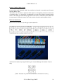
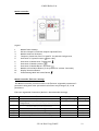
Control Panel
RVA47 Cascade Manager
Legend
1.
2.
3.
4.
5.
Room Temperature Set Point Adjuster. Assumed Room Temperature if no Room Unit Fitted
Parameter Setting Buttons - / +
Parameter Line Selection Buttons Down / Up
Display Screen
Mode Selection Buttons. Operating Mode Indication
Automatic Operation
Continuous Operation On / Off
Standby
6.
HWS On / Off
Manual Override Button and Indicator
7.
Manual Operation On / Off
Computer Access Port
221106 Draft Copy E&OE
18
© MHS Boilers Ltd
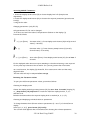
Module Controller
Legend
1.
2.
3.
4.
5.
Module Power Isolator
Infrared Output to Flue Gas Analyser Optional Extra.
Module Numerical Indicator
Temporary Connection Port For QAA73 for LMU 64 Configuration.
Indication of System Pressure
(Not Used)
6.
Indication of Module Over Temperature
7.
8.
9.
10.
Indication of Module Lockout
Indication of Module Burner Activation
Module Lockout Reset Button (To be pressed for at least 3 Seconds)
Display Alteration Button
11.
Commissioning Mode Activation Button
Module Controller End User Settings.
The Module Controller provides access to the End User adjustable parameters P
parameters along with other operational information only settings A, B, C & D
parameters.
End User Adjustable Parameters. (Default = Recommended Settings)
Parameter
P0
P1
P2
Function
Range
Default
Required Module Flow Temperature / Room
Temperature. (Outside air sensor attachment dependant. Without = Flow Temperature)
Required HWS Set Point.
20-900C / 10-300C
85 / 200C
10-800C
600C
NA
NA
-- / 40
-31 / +31
NA
NA
32
0
(Only Used if the Module is Directly Controlling HWS Generation)
P3
P4
P5
P6
Not used in This Configuration
Not used in This Configuration
Weather Compensation Curve Heating Circuit 1
Weather Compensation Curve Parallel Displacement
221106 Draft Copy E&OE
19
© MHS Boilers Ltd
Accessing Module Parameters
1. Press the display mode button (10) to choose display level «P» (keep button
depressed).
2. Press the display mode button (10) to choose the required parameter (press button
briefly).
3. Adjust the value:
Changing parameters: (only P0...P6)
Only parameters P0...P6 can be changed.
To do this, wait until the value of the parameter flashes on the display (3).
Proceed as follows:
P ❍ (+) or (Enter)
Increase value (+): Press display mode button (10) briefly several
times (< 1 second)
❍ (-)
Decrease value (-): Press chimney sweep button (11) briefly
several times (< 3 seconds)
P ❍ (+) or (Enter)
Save value (Enter): Press display mode button (10) for at least 3
seconds
If the displayed value does not require amending or the altered setting is not required
do not press any buttons on the controller for a period greater than 12 seconds.
As a confirmation, the display (3) shows P0...P6 in consecutive order and the newly
adjusted value.
The new value will only be adopted after storage.
Reviewing the Parameter Values
To query the different parameter values, proceed as follows:
Choosing the display mode
Choose the display mode by pressing button (10) for more than 3 seconds (display (3):
A...). Keep button (10) depressed to reach the different display levels b, C, d, P
and back to A.
Release the button when the required display level is reached (A, b, C, d, P).
Choosing and displaying individual values or parameters
To change between the different values or parameters (0… max. 7) of the different
display
levels (A, b, C, d, P), press button (10) briefly.
The current value appears about 2 seconds after choosing the relevant parameter.
221106 Draft Copy E&OE
20
© MHS Boilers Ltd
Module Operating Codes
221106 Draft Copy E&OE
21
© MHS Boilers Ltd
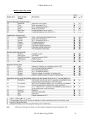
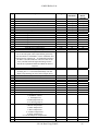
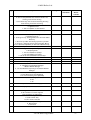
Appliance Error Codes
If a fault is encountered within the appliance or Cascade LPB network, a fault code will
be generated and displayed by the failing module and all LPB networked RVA47 Cascade
Managers.
If a fault is encountered by a module the respective code will be displayed along with a
flashing LED. Three digit codes will be displayed in two consecutive sections. I.e. 1-53 = 153.
If a fault is encountered by a RVA47 Cascade Manager or communicated to a RVA47
Cascade Manager via the LPB network ER will be generated on the display.
Opening the controllers flap and pressing the Down PROG button twice will gain access
to parameter line 50 where the generated fault code can be reviewed.
In either case the fault code should be noted for future reference.
If the fault is related to a specific module the unit can be rest by pressing the Lockout
Reset Button (9) for at least 3 seconds.
If the fault is related to a RVA47 Cascade Manager or the LPB communication network
the fault code will clear automatically following the rectification of the fault.
This is also applicable following the rectification of any module fault. This can take up to
10 minutes.
Fault Code
E-0
E-10
E-20
E-26
E-28
E-40
E-46
E-50
E-52
E-58
E-60
E-61
E-62
E-77
E-78
E-81
E-82
E-86
E-91
E-92
E-100
E-110
E-111
Description
No Error Detected
Outside Air Sensor Fault / Not Detected
Flow Water Sensor Fault / Not Detected
System Flow Sensor Faulty / Not Detected
Flue Gas Sensor Fault / Not Detected
Return Water Sensor Fault / Not Detected
System Return Water Sensor Fault / Not Detected
HWS Sensor Short Circuit 1
HWS Sensor Short Circuit 2 (Not Used)
HWS Volt Free Switch Fault / Not Detected
Faulty Room Sensor
Faulty Room Sensor
Incorrect Room Unit Connected
Air Pressure Sensor Not Detected (Not Used)
Water Pressure Sensor Defective (Not Used)
LPB Short Circuit (Boiler Cascade Wiring)
LPB Address Conflict (Boiler Cascade Settings)
Short Circuit on PPS Connection (Not Used in Streamline Configuration)
EEPROM
Hardware Malfunction
Conflict Between Time of Day Master Control (Boiler / QAA70 / RVA47)
Module Water Temperature Overheat
Module Temperature Too High (Auto Resetting)
221106 Draft Copy E&OE
22
© MHS Boilers Ltd
E-113
E-117
E-118
E-119
E-124
E-130
E-131
E-132
E-133
E-134
E-135
E-140
E-142
E-145
E-146
E-147
E-148
E-150
E-151
E-152
E-153
E-154
E-160
E-161
E-162
E-164
E-166
E-180
E-181
E-183
Flue Gas Temperature overheat (Not Used)
High System Water Pressure Sensor (Not Used)
Low System Water Pressure Sensor (Not Used)
System Water Pressure Switch Activated (Below 0.8 bar)
Module Temperature Too High (Auto Resetting)
Flue Temperature Too High (Auto Resetting)
Fault With Burner
External Safety Interlock Activated (Open Circuit)
No Flame Detected After Final Ignition Attempt
Flame Extinguished During Operation
Air Supply Error (Not Used)
LPB Segment / Address Not Recognized (Boiler Cascade Settings)
LPB Missing Partner (Boiler Cascade Settings)
Wrong Device Connected to PPS Circuit (Not Used in Streamline Configuration)
Unrecognized Plant Configuration
Burner Modules Not Connected (PPS Circuit Not Used in Streamline Configuration )
LPB Interface Not Configured (Boiler Cascade Settings)
General Boiler Fault
Module LMU64 Controller Malfunction
Module LMU64 Controller Parameter Programming Error
Module Control Interlocked
Module Operating Outside of Predefined Parameters. (System Hydraulic Error.)
Fan Not Reaching Set Point
Module Combustion Fan Speed Too High
Air Pressure Switch Fault (Not Used)
Flow Switch / Pressure Switch Open (Not Used)
Air Pressure Switch Fault (Not Used)
Module Operating in Chimney Mode 100% Output
Module Operating in Commissioning Mode
Module Controller / QAA73 Room Unit in Parameter Setting Mode
221106 Draft Copy E&OE
23
© MHS Boilers Ltd
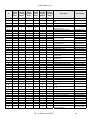
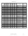
Control Parameter Default Settings.
RVA47 Cascade Manager Settings.
The Standalone and Cascade Master units are preset for correct operation.
The following Pages detail the parameters of the RVA47 Cascade Manager and the
Standard Factory settings, please note, the installer/commissioning engineer may have
changed some of these settings to suit the system installed.
There are two levels of access available, as follows. If you cannot access a particular
parameter line, please consult with MHS Boilers Technical Department for further
assistance.
Level One
(End User)
Level Two
(Installer)
Level Three
(OEM)
-
-
-
Open The Hinged Flap.
Use either of the
Program Buttons to access the desired parameter
line. (Parameter Line range 0-50)
Buttons to alter the required parameter.
Use the
Once all alterations have been completed press the AUTO button to exist this
level.
Open The Hinged Flap.
Press & Hold the
Program Buttons simultaneously for more than 3
seconds until Parameter # 51 appears.
Use either of the
Program Buttons to access the desired parameter
line. (Parameter Line range 51-173)
Buttons to alter the required parameter.
Use the
Once all alterations have been completed press the AUTO button to exist this
level.
Open The Hinged Flap.
Press & Hold the
Program Buttons simultaneously for up to 9 seconds
until - - - - - appears.
A password will be required to access this level.
Available upon request from MHS Boilers Technical Services Department.
Use either of the
Program Buttons to access the desired parameter
line. (Parameter Line range 2-92)
Buttons to alter the required parameter.
Use the
Once all alterations have been completed press the AUTO button to exist this
level.
Complete RVA47 Cascade Controller Parameter Settings.
The defaults indicated below are for standard systems.
If additional control features are required alteration will have to be made.
Please refer to the RVA47 manual for additional details.
#, -, ----
Indicates where an input can be made if required.
Indicates where an input can not be made and a sensed / attenuated
figure is displayed. ‘OFF’ will be displayed if the +/- buttons are used.
221106 Draft Copy E&OE
24
© MHS Boilers Ltd
[#]
1
2
3
4
5
6
7
8
9
10
11
13
14
15
16
17
18
19
23
30
31
32
33
34
35
50
51
52
53
Description
End User Level
Time of Day
Weekday
Date
Year
Day of Week
Heating Time Switch 1st On Time
Heating Time Switch 1st Off Time
Heating Time Switch 2nd On Time
Heating Time Switch 2nd Off Time
Heating Time Switch 3rd On Time
Heating Time Switch 3rd Off Time
Required HWS Temperature
Heating Night Setback Temperature
Frost Protect Temperature
Summer/Winter Changeover Temperature
Weather Compensation Curve.
If a 0-10 volt signal is the required heat generation
control method for the RVA47 / boiler installation this
setting must be adjusted to -- on all RVA47s present in
the boiler cascade installation. This will result in the
Auto, On/Off and Frost lights becoming inactive.
Alteration to parameter #170 and #172 will also be
required.
Actual Room Temperature
Actual Outside Temperature
(Pressing the + & - buttons simultaneously until the
display stops flashing will reset the averaged value.)
Restore User Level Factory Presets
Hot Water Time Switch 1st On Time
Hot Water Time Switch 1st Off Time
Hot Water Time Switch 2nd On Time
Hot Water Time Switch 2nd Off Time
Hot Water Time Switch 3rd On Time
Hot Water Time Switch 3rd Off Time
Fault Code Display
Engineer Level
Output Test
0. Automatic control
1. All outputs off
2. HWS pump/valve on
3. Circulating pump on
Input Test
0. Return Temperature
1. HWS Temperature
2. Flow Temperature
3. Outside Temperature
4. Room Temperature
5. 0-10 Volt Required Temperature
Plant Type
Range
150 & 225
Standalone
150 & 225
Master
Cascade
00:00-24:00
1-7
00:00
1900-3000
00:00-24:00
00:00-24:00
00:00-24:00
00:00-24:00
00:00-24:00
00:00-24:00
40-60
10-30
4-15
8-30
0-40
As Required
As Required
As Required
As Required
As Required
06:00
22:00
55
16
10
30
32
As Required
As Required
As Required
As Required
As Required
06:00
22:00
55
16
10
30
32
0-50
-50-+50
---
---
0-1
00:00-24:00
00:00-24:00
00:00-24:00
00:00-24:00
00:00-24:00
00:00-24:00
0-255
0
06:00
22:00
--
0
06:00
22:00
--
0-3
0
0
0-5
0
0
0-100
--
--
1.7 1.5 6.7 1-7
221106 Draft Copy E&OE
25
© MHS Boilers Ltd
[#]
Description
Range
150 & 225
Standalone
56
57
59
60
61
62
66
69
70
71
72
75
76
77
95
100
101
Actual System Flow Temperature
Actual System Return Temperature
Actual System HWS Temperature
Attenuated Outside Air Temperature
Composite Outside Air Temperature
Outside Air Temperature Source
Maximum System Flow Temperature
Maximum HWS Temperature
Nominal Room Temperature Set Point
Set Point Of Room Temperature
System Flow Temperature Set Point
Modules Available in Cascade
Lead Module in Cascade
Hour of Operation Until Sequence Change
Heating Pump Output (HKP) Output Functions
Displacement Of Weather Compensation Curve
Gain Factor/Room Influence
0. Active
1. Inactive
Room Temperature Switching Differential
Minimum System Flow Temperature
Maximum System Flow Temperature
Building Construction Type
0. Heavy
1. Light
Adaptation of Heat Curve
0. Inactive
1. Active
Optimum Start Time Maximum Forward Shift.
00:00 Inactive
Optimum Stop Time Maximum Forward Shift
00:00 Inactive
Heating Zone Quick Setback Constant
Over Heat Protection Heating Zone Pump
Legionella Protection Function 0. Off. 1. On
Legionelle Protection Temperature
HWS Pump Operation Function. (Stored > Flow Temp)
0. Off 1. Always On 2. Only On When Boiler is
Interlocked Off Via 170=3
Reduced HWS Temperature Set Point
HWS Time Control
0. 24 Hours per Day
1. As Heating Time Switch Settings
2. As HWS Time Switch Settings
HWS Pump Control
0. Heating Time Switch Setting Apply
1. HWS Time Switch Settings Apply
HWS Control in Cascade System
0. Controlled Via Master RVA47 Manager
1. Controlled Via All RVA47 Managers in Segment
2. Controlled Via All RVA47 Managers In LPB
System
0-140
0-140
0-140
-50-+50
-50-+50
00.01/14.16
8-85
8-85
0.0-35.0
0.0-35.0
0-140
00.1/16.3
00.1/16.3
0.990
1-5
-4.5 - +4.5
0-1
--------------3
0
1
150 & 225
Master
Cascade
--------------3
0
1
---/0.5-4
8-95
8-95
0-1
--8
82
1
--8
82
1
0-1
0
0
00:00-06:00
00:00
00:00
00:00-06:00
00:00
00:00
0-20
0-1
0-1
8-95
0-2
2
0
0
65
0
2
0
0
65
0
8-70
0-2
40
2
40
2
0-1
1
1
0-2
2
2
102
103
104
105
106
107
108
109
110
117
118
119
120
121
122
123
221106 Draft Copy E&OE
26
© MHS Boilers Ltd
[#]
Description
Range
150 & 225
Standalone
124
HWS Charging Cycles Per 24 Hour Period
0. One Per Day with 2.5 Hour Forward Shift from
Heating Time Switch Setting
1. Several Per Day with 1 Hour Forwarding Shifting
from Heating Time Switch Setting
HWS Temperature Control
0. QAZ21 Sensor
1. Volt Free Enable via Thermostat
System Flow Temperature Boost When HWS Enabled
0-1
1
150 & 225
Master
Cascade
1
0-1
0
0
0-30
20
20
0-3
1
1
10-990
0-3
10
0
10
0
00.1-16.3
1-120
0-1800
0-16
--1
30
1
--1
30
1
0-14
0
0
0-1
1
1
On/Off
On
On
125
126
127
143
HWS Priority / Shifting
0. Absolute Priority
1. Shifting Priority. Heating Reduced to Increase HWS
Recovery
2. No Priority. HWS and Heating Operate in parallel
3. Shifting / Absolute Heating Switched OFF, Mixing
Circuit Decreased (RVA46) to Increase HWS Recovery.
Hours Of Operation Prior to Sequence Rotation
Changeover Sequence Program
0. No Exemptions
1. The First Module is Exempt
2. The Last Module is Exempt
3. The First and Last Modules are Exempt
Module Designated as Fixed Lead Unit
Cascade Enable Delay Time
Anti Cycling Time (Seconds)
LPB Control Address
0. Standalone Single RVA47 Manager
1. Master RVA47 Manager
2….16. Slave RVA47s Operating From Master RVA47
Manager
LPB Control Segment
0. Heat Generating Units (RVA47s)
1…14. Heat Consuming Units (RVA46s)
LPB Power Supply
0. Off
1. On
Operation of LPB Power Supply
144
Display of LPB Communication
On/Off
On
On
145
Changeover Via LPB Connection
0. All Controllers in Same Segment
1. All Controllers in LPB System
Summer/Winter Changeover Via LPB
0. Local Control Only
1. Entire Control Via LPB
Central Standby Switching
0. Deactivated
1. Activated
0-1
1
1
0-1
0
0
0-1
0
0
130
131
132
133
134
140
141
142
146
147
221106 Draft Copy E&OE
27
© MHS Boilers Ltd
[#]
Description
Range
150 & 225
Standalone
148
Clock Mode
0. Autonomous All Clocks Can Have Different Times
1. System Time Without Adjustment
2. System Time With Adjustment
3. System Clock Master. There Can Only be One Master
Auto Time Adjustment Spring
Date and Month of Last Sunday in March
Auto Time Adjustment Autumn
Date and Month of Last Sunday in October
Operation of H1 Terminal
0. Changeover of Operation When Volt Free Switch is
Made. (HWS Stopped)
1. Changeover of Operation When Volt Free Switch is
Made. (HWS Unaffected)
2. Minimum Flow Temperature Maintained When Volt
Free Switch is Made. (Set at 171.)
3. Heat Generation Stopped When Volt Free Switch is
Made.(Frost Active)
4. 0-10 Volt Control to Vary System Flow Temperature.
(Curve set at 172)
(Terminal #1. 0-10 volt. Terminal #2. Ground.)
{If a 0-10 volt signal is the required heat generation
control method for the RVA47 / boiler installation this
setting must be adjusted to 4. Alterations must also be
made to parameter #17. The setting must be adjusted
from 32 to – on all RVA47s present in the boiler
cascade installation. This will result in the Auto,
On/Off and Frost lights becoming inactive. Possible
alterations to parameter #172 may also be required.}
Minimum Temperature Set Point Via H1 (170 = 2)
Maximum Temperature Set Point Via H1 (170 = 4)
Operating Action of H1 control contacts.
0. The contact is Normally Closed.
1. The contact is Normally Open.
{The RVA47 will operate according to its internal
time switches and presets.
If a remote BMS is controlling the RVA47 via a
Volt Free switch across H1 ‘0’ should be
inserted.
This will allow the boilers operate when the Volt
Free switch is made and stopped (Blocked.) when
the switch is opened.
If you are controlling the lead (master) RVA/Boiler
via a volt free switch across H1, all slave modules
should be left with ‘1’ as the input.
This will allow the AUTO light and the OFF light to
indicate their operational mode dictated by the lead
(master) RVA/Boiler.}
OEM Level
Maximum Module Temperature
When Operating In Manual Mode
0-3
2
150 & 225
Master
Cascade
2
Date/Month
25.03
25.03
Date/Month
25.10
25.10
0-4
0
0
8-95
5-130
0-1
80
82
1
80
82
1
8-120
82
82
149
150
170
171
172
173
2
221106 Draft Copy E&OE
28
© MHS Boilers Ltd
[#]
Description
Range
150 & 225
Standalone
8
Pump Run On Time
System Heating (HKP) and HWS (SLP) Pumps
Minimum System Return Temperature
Room Influence Gain Factor
Boost Room Temperature Set Point
Room Sensor Dependant (QAA10/50/70)
Increase. Heat Up Time Reduced
Decrease Heat Up Time Increased
Frost Protection
0. Frost Protection Program Disabled
1. Frost Protection Program Enabled
Heat Gains
Increase. If Heat Gains are High
Decrease. If Heat Gains are Low
Adaptation Sensitivity 1
Outside Air Range 4-120C
Adaptation Sensitivity 2
Outside Air Range <40C
Maximum HWS Set Point
HWS Switching Differential (QAZ21 Sensor Only)
Legionella Function 0. Off 1. On.
Cascade Strategy
1-3 Automatic
4-6. Fixed
Minimum % Output reached Prior to Switching Off a
Module In the Cascade
Maximum % Output Reached Prior to Switching On a
Module In The Cascade
Time Spent By Module On Ignition Rate Prior to
Modulation (Delay Time Between Modules)
Minimum Temperature Difference Between Flow/
Return Sensor Readings Prior to The Return Sensor
Becoming Lead
Display Default
0. Time of Day
1. System Flow Temperature (CA)
Software Version
RVA47 Manager Operating Hours
0-20
3
150 & 225
Master
Cascade
3
8-95
0-20
0-20
8
4
5
8
4
5
0-1
1
1
-2-+4
0
0
1-15
15
15
1-15
15
15
8-80
0-20
0-1
1-6
60
5
0
3
60
5
0
3
5-100
20
20
5-100
85
85
0-1200
0
0
0-20
2
2
1
1
#
--
#
--
22
30
32
33
35
36
37
40
41
42
50
51
52
56
60
90
91
92
00.0-99.9
0-500,000
221106 Draft Copy E&OE
29
© MHS Boilers Ltd
Control Parameter Default Settings.
Module LMU64 Setting.
The Standalone and Cascade Master units are preset for correct operation.
However the slave units may require modest parameter updating. (Usually limited to H605)
The following Pages detail the parameters of the modules and the Standard Factory settings,
please note, the installer/commissioning engineer may have changed some of these settings to suit
the system installed.
To access the parameters detailed below a QAA73 Room Unit is require. The unit must be
connected to the respective Module Controller Via the dedicated Plug, Behind cover plate (4) or
directly to the respective LMU64 module controller. Via the X10:01 Terminal.
There are two levels of access available, as follows. If you cannot access a particular parameter
line, please consult with MHS Boilers Technical Department for further assistance.
Level One
(Installer)
-
Press & Hold the
Program Buttons simultaneously for at
least 3 seconds until INITIALIZATION BMU PARAMETER is
displayed on the appears on the screen. Use the
Program
Buttons to access the desired parameter line. Use the
Button to alter the displayed parameter to the required setting.
Level Two
(OEM)
-
Whilst in Level One Press & Hold the
Program Buttons
simultaneously for at least 3 seconds until INITIALIZATION BMU
SERVICE is displayed on the screen. Use the
Program
Buttons to access the desired parameter line. Use the
Button to alter the displayed parameter to the required setting.
An altered parameter will be saved to the controllers memory by leaving the displayed parameter
when either of the
Program Buttons are pressed.
To exit the parameter review and amendment levels the INFO Button of the QAA73 must be
pressed. Any unsaved parameter alterations will be lost if the QAA73 is version 1.3 or lower.
QAA73 #
H90
H91
H93
H94
H503
H504
H505
150 & 225
150 & 225
Cascade
Cascade Slave
Master
Defaults
Defaults
Description
Range
150 & 225
Standalone
Defaults
Reduced Temperature for DHW
8….60
10
10
10
0…1
0
0
0
0…1
0
0
0
0…1
0
0
0
20 ... 90 °C
20
20
20
20 ... 90 °C
90
90
90
20 ... 90 °C
85
85
85
DHW Production Control
(0=Time control 1=Constant)
DHW Production Control 0=Non Eco 1=Eco
DHW Secondary Pump Control
(0= As H91. 1= As HWS Time Switch)
(K2, X2:03, H615:6)
Minimum boiler setpoint temperature
(20 °C<=TkSmin<=TkSmax)
Maximum boiler setpoint temperature
(TkSmin<=TkSmax<=90 °C)
Boiler setpoint at design outside temperature
221106 Draft Copy E&OE
30
© MHS Boilers Ltd
QAA73 #
H506
H507
H516
Description
Minimum flow setpoint temperature
(20 °C<=TvSmin<=TvSmax)
Maximum flow setpoint temperature
(TvSmin<=TvSmax<=90 °C)
Summer / winter changeover temperature
(30 °C: S / W changeover deactivated)
150 & 225
150 & 225
Cascade
Cascade Slave
Master
Defaults
Defaults
Range
150 & 225
Standalone
Defaults
20 ... 90 °C
25
25
25
20 ... 90 °C
90
90
90
8 ... 30 °C
18
18
18
H532
Heating curve slope heating circuit 1
1 ... 40
32
32
32
H533
Heating curve slope heating circuit 2
1 ... 40
32
32
32
H536
Maximum speed at maximum output in heating
mode
(maximum speed limitation)
0 ... 9950 rpm
7000
7000
7000
0 ... 100 %
100
100
100
0 ... 9999 kW
15
15
15
0 ... 9999 kW
75
75
75
0 ... 255 min
10
10
10
0 ... 3600 s
300
300
300
H541
H542
H543
H544
H545
Maximum degree of modulation in heating mode
(LmodTL <= PhzMax <= LmodVL)
Minimum boiler output in kW
Maximum boiler output in kW
(lower calorific value)
(lower calorific value)
Overrun time of pumps, max. 210 min
(setting 255: continuous operation of Q1)
Minimum burner pause time
(heat demand-dependent switching hysteresis)
H551
Constant for quick setback without room influence
0 ... 20
2
2
2
H552
Hydraulic system adjustment
0 ... 255
80
80
80
b0=1
b1=0
b2=1
b3=1
b4=0
b5=1
b6=0
b7=0
b0=0
b1=0
b2=0
b3=0
b4=1
b5=0
b6=0
b7=0
b0=1
b1=0
b2=0
b3=0
b4=0
b5=0
b6=1
b7=0
b0=1
b1=0
b2=1
b3=1
b4=0
b5=1
b6=0
b7=0
b0=0
b1=0
b2=0
b3=0
b4=1
b5=0
b6=0
b7=0
b0=1
b1=0
b2=0
b3=0
b4=0
b5=0
b6=1
b7=0
b0=1
b1=0
b2=1
b3=1
b4=0
b5=1
b6=0
b7=0
b0=0
b1=0
b2=0
b3=0
b4=1
b5=0
b6=0
b7=0
b0=1
b1=0
b2=0
b3=0
b4=0
b5=0
b6=1
b7=0
150
150
150
H554
Setting flags: status code open-circuit sensor for
ANx channel suppressed / not suppressed
0 ... 255
H555
Setting flags
0 ... 255
H558
Setting flags
0 ... 255
H596
Running time of actuator in heating circuit 2
(TimeOpening / TimeClosing)
221106 Draft Copy E&OE
30 ... 873 s
31
© MHS Boilers Ltd
QAA73 #
Description
Range
150 & 225
Standalone
Defaults
150 & 225
150 & 225
Cascade
Cascade Slave
Master
Defaults
Defaults
LPB device number of LMU
H605
* Module numbering
150 Stand Alone & Master Upper 2 Lower 3
Cascade Slave Upper 4, Lower 5………16 ETC
225 Stand Alone & Master Upper 2, Middle 3, Lower 4
Cascade Slave Upper 5, Middle 5, Lower 6………16 ETC
H606
LPB segment number of LMU
H614
0 ... 16*
2,3, (150)* 2,3, (150)* 4,5-16 (150)*
2,3,4 (225)* 2,3,4 (225)* 5,6,7-16(225)*
0 ... 14
0
0
0
Program input LMU basis
0 ... 255
3
3
3
H615
Function programmable output K2 LMU
0 ... 255
0
0
0
H618
Progr input on clip-in function module
0 ... 255
0
0
0
H619
Function output1 clip-in function module
0 ... 255
0
0
0
H620
Function output2 clip-in function module
0 ... 255
0
0
0
H621
Function output3 clip-in function module
0 ... 255
0
0
0
H622
Maximum value of heat demand with external
predefined temperature setpoint
5 ... 130 °C
85
85
85
b0=1
b1=0
b2=0
b3=0
b4=0
b5=0
b6=0
b7=0
b0=1
b1=0
b2=0
b3=0
b4=0
b5=0
b6=0
b7=0
0
0
(5 °C< = TAnfoExtMax< = 130 °C)
H630
Setting flags of maintenance alarms
0 ... 255
b0=1
b1=0
b2=0
b3=0
b4=0
b5=0
b6=0
b7=0
H636
Months (interval) since last service visit
0 ... 255
months
0
H700
1st Historical Fault – Number of Occurrences.
H701
1st Historical Fault – Operating Phase.
H702
1st Historical Fault – Operating Error Code
H703
2nd Historical Fault – Number of Occurrences.
H704
2nd Historical Fault – Operating Phase.
H705
2nd Historical Fault – Operating Error Code
H706
3rd Historical Fault – Number of Occurrences.
H707
3rd Historical Fault – Operating Phase.
H708
3rd Historical Fault – Operating Error Code
H709
4th Historical Fault – Number of Occurrences.
H710
4th Historical Fault – Operating Phase.
H711
4th Historical Fault – Operating Error Code
221106 Draft Copy E&OE
32
© MHS Boilers Ltd
QAA73 #
Description
H712
5th Historical Fault – Number of Occurrences.
H713
5th Historical Fault – Operating Phase.
H714
5th Historical Fault – Operating Error Code
H715
Current Historical Fault – Number of Occurrences
H716
Current Historical Fault – Operating Phase.
H717
Current Historical Fault – Operating Error Code
H718
Hours run burner
H719
Hours run heating mode
H720
Hours run DHW heating
H721
Hours run zone
H722
Start counter
H727
Current Fault Code – ALBATROS Error Code
H728
1st Historical Fault – ALBATROS Error Code
H729
2nd Historical Fault – ALBATROS Error Code
H730
3rd Historical Fault – ALBATROS Error Code
H731
4th Historical Fault – ALBATROS Error Code
H732
5th Historical Fault – ALBATROS Error Code
H732
Current Historical Fault – ALBATROS Error Code
H755
Measured value of ionization current
Range
0 ... 131070
hrs
0 ... 131070
hrs
0 ... 131070
hrs
0 ... 131070
hrs
0 ... 327675
150 & 225
Standalone
Defaults
150 & 225
150 & 225
Cascade
Cascade Slave
Master
Defaults
Defaults
0
0
0
0
0
0
0
0
0
0
0
0
0
0
0
0 ... 583
-
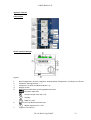
Module Controller
Legend
1. Module Power Isolator
2. Infrared Output to Flue Gas Analyser Optional Extra.
3. Module Numerical Indicator
4. Temporary Connection Port For QAA73 Unit
5. Indication of System Pressure
(Not Used)
6. Indication of Module Over Temperature
7. Indication of Module Lockout
8. Indication of Module Burner Activation
9. Module Lockout Reset Button (To be pressed for at
least 3 Seconds)
10. Display Alteration Button
11. Commissioning Mode Activation Button
221106 Draft Copy E&OE
33
© MHS Boilers Ltd
Commissioning The Appliance
Pre-Commissioning Checks
Prior to undertaking the commissioning of the unit please ensure that the system water
has been cleansed and treated with a suitable inhibitor as detailed in Filling the system
and system water quality.
Prior to applying power to the individual modules their dedicated circulation pumps
should be bleed and checked to ensure free rotation of the armature.
Combustion System Commissioning.
The commissioning function enables the boiler to be started up in heating mode by
pressing the
Chimney Sweep Button (11) on the module controller.
There are two levels of operation accessed via the Chimney Sweep Button (11)
Operation at Maximum Output With No Adjustment.
Pressing the
Chimney Sweep Button (11) for more than 3 seconds but less than 6
seconds places the respective module in High Fire mode.
Chimney Sweep
To indicate that the module is operating under the control of the
Button the display (3) will indicate SF and the red Lockout LED (7) will flash with a
single pulse.
This mode is maintained until the limit thermostat temperature is reached or the
Chimney Sweep Button is pressed from more than 1 second.
Operation at Maximum or Minimum Output For Flue Gas Analysis and Gas Valve
Adjustment
Pressing the
Chimney Sweep Button (11) for more than 6 seconds. places the
respective module in High Fire mode.
Chimney Sweep
To indicate that the module is operating under the control of the
Button the display (3) will indicate 100 for High Fire and 0 for Low Fire and the red
Lockout LED (7) will flash with a double pulse.
To alternate the module between High Fire and Low Fire the
Chimney Sweep and
P Buttons must be pressed for less than 1 second.
P
Button
High Fire
Button
221106 Draft Copy E&OE
Low Fire
34
© MHS Boilers Ltd
This mode is maintained until the limit thermostat temperature is reached or the
Chimney Sweep or P Button is pressed from more than 1 second. The module stops
operating when the button is released.
Whilst the module is operating under the control of the Chimney Sweep Button (with
adjustment) the gas valve can be adjusted to give correct flue gas analysis readings.
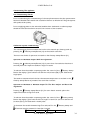
Each module is equipped with a modulating gas valve.
The modulating gas valve must be set at High Fire and Low Fire to ensure correct
operation throughout its modulating range.
It is advisable to check the combustion figures on High and Low Fire prior to carrying
out any adjustments.
Adjusting the High Fire has a marked effect on the Low Fire figures.
Where as adjusting the Low Fire has little effect on the High Fire figures.
The High fire adjustment is carried out via the 2.5mm Allen Key socket D
The High Fire adjustment is a Gate type restrictor.
Therefore turning the screw clockwise will close the gate and thus restrict the quantity
of gas passing through to the burner.
The Low fire adjustment is carried out via the 2.5mm Allen Key socket N
The Low Fire adjustment is a diaphragm governor.
Therefore turning the screw clockwise will increase the pressure on the diaphragm and
thus increase the quantity of gas passing through to the burner.
Legend
A.
B.
D.
N.
Valve Inlet Gas Pressure Test Point
Valve Outlet Gas Pressure Test Point
High Fire Adjuster (Gate Type)
Low Fire Adjuster (Governor Type)
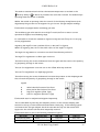
Each module must be analysed and adjusted separately.
This is undertaken by inserting the analysers probe in to the silicone sampling tube
secured to the top of each module and sealed with a black plug. If fluctuating figures
are obtained the flue gas analyser should be inserted directly into the module flue
spigot once the silicone tube has been temporally removed.
Each module must be set to the following combustion figures.
Gas Type
Injector Size
High Fire
Natural Gas (G20)
15mm (Exploded Part #79)
8.5% C02
LPG (G31)
10mm (Exploded Part #79)
11.0% CO2
221106 Draft Copy E&OE
Low Fire
9.0% CO2
11.0% CO2
35
© MHS Boilers Ltd
Internal Wiring
Module Operation Indication
Communication Operation Indications
The RED LED on the OCI420 communication clip mounted on the front of each LMU64 module
controller flashes to indicate the detected operational status of the module dictated by the LPB
communication from the Streamline FS Masters RVA47 Cascade Manager.
LED FLASH STATUS
INTERPRETATION OPTIONS
LED ON Constantly
OCI420 not configured to operate with LMU64
LED OFF Constantly
OCI420 Configured. LPB Short Circuit / No Power.
LED ON 93% OFF 7%
OCI420 and LUM64 Not Compatible / LPB Address inadmissible.
LED ON 5% OFF 95%
Boiler being controlled via LPB and required to be not operating.
LED ON 5% OFF 20% ON 5% OFF 70%
Boiler being controlled via LPB and required to be operating.
221106 Draft Copy E&OE
36
© MHS Boilers Ltd
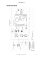
Internal Wiring Diagram
221106 Draft Copy E&OE
37
© MHS Boilers Ltd
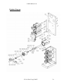
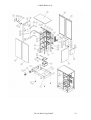
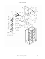
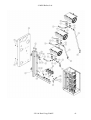
Exploded Diagram
221106 Draft Copy E&OE
38
© MHS Boilers Ltd
221106 Draft Copy E&OE
39
© MHS Boilers Ltd
221106 Draft Copy E&OE
40
© MHS Boilers Ltd
221106 Draft Copy E&OE
41
© MHS Boilers Ltd
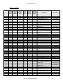
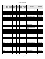
Spares Listings
#
150 FS
Stand
Alone
150 FS
Cascade
Master
150 FS
Cascade
Slave
225 FS
Stand
Alone
225 FS
Cascade
Master
225 FS
Cascade
Slave
1
2
3
4
5
1
8
32
32
4
1
8
32
32
4
1
8
32
32
4
1
8
32
32
4
1
8
32
32
4
1
8
32
32
4
6
4
4
4
4
4
4
7
8
9
10
11
12
1
2
44
46
9
1
1
2
44
46
9
1
1
2
44
46
9
1
1
2
45
47
9
1
1
2
45
47
9
1
1
2
45
47
9
1
13
25
25
25
25
25
25
14
15
16
17
18
19
20
21
22
23
24
25
26
27
28
29
30
31
32
33
1
1
1
1
16
1
4
2
4
2
2
2
1
21
1
1
4
8
2
1?
1
1
1
1
16
1
4
2
4
2
2
2
1
21
1
1
4
8
2
1
1
1
1
1
16
1
4
2
4
2
2
2
1
21
1
1
4
8
2
1
1
1
1
1
19
1
4
3
6
3
3
3
1
21
1
1
4
8
3
1?
1
1
1
1
19
1
4
3
6
3
3
3
1
21
1
1
4
8
3
1
1
1
1
1
19
1
4
3
6
3
3
3
1
21
1
1
4
8
3
1
33
---
1
1
---
1
1
34
2
2
2
2
2
2
35
1
1
1
1
1
1
36
1
1
1
1
1
1
37
38
39
40
41
42
43
44
2
1
2
14
12
2
1
1
2
1
2
14
12
2
1
1
2
1
2
14
12
2
1
1
2
1
2
14
12
2
1
1
2
1
2
14
12
2
1
1
2
1
2
14
12
2
1
1
221106 Draft Copy E&OE
Description
Base Tray
Base Tray Securing Bolts
Toothed Washer ; A5.3
Hexagonal Nut ; M5
Leveling Feet ; M12 x 98
Hexangular Nut for Levelling
Feet ; M12;
Roller Mounting Panel
Roller D= 80 mm, H= 108 mm
Washer ; 8,4
Bolt ; M8 x 16
Washer 8,4 x 24 x 2
Vertical Support Left Front
Rectangular Nut M8, 30 x 20 x
4
Vertical Support Right Front
Vertical Support Left Rear
Vertical Support Right Rear
Vertical Support Support Left
Rectangular Nut; M8;
Vertical Support Support Right
Brace Support
Heat Exchanger Cradle
Pop rivet 6,4 x 12,5
Cable Brackets D=12,7
Cable Bracket Bolt M5
Heat Exchanger Support Bolt
Horizontal Frame Support Left
Case Mounting Stud
Horizontal Frame Support Right
Rear Casing Panel
Cable Supports
Cable support screws
Heat Exchanger Support
Low Loss Header Assembly
Distribution Header Assembly
Cascade Units Only
Return Senor Pocket ½"x80mm
Return Temperature Sensor
QAZ21/0720
Flow Temperature Sensor
QAZ21/0720
Automatic Air Releases 3/8"
Water Pressure Switch, 0,8 bar
Sealing Washer
Washers 10,5; DIN 125, St A3C
Mounting Bolts M10x20;
Blank Plug M10; DIN 934 A3B
Drain Valve Support
Flue Gas Collector DN 160
Part Number
96.35460-7020
94.15393-5001
On Request
On Request
94.17230-7001
On Request
96.36560-7032
94.17273-7001
On Request
On Request
On Request
96.35760-7004
95.99196-0022
96.35760-7003
96.35760-7006
96.35760-7005
96.35760-7011
On Request
96.35760-7012
96.35760-7007
96.36560-7030
On Request
95.99186-0060
On Request
94.17230-7002
96.35760-7001
96.36689-7008
96.35760-7002
96.35460-7021
96.39658-7001
On Request
96.36560-7031
96.36144-7042
96.36144-7046
96.38235-7001
96.00022-0943
94.19314-5001
94.74400-5003
96.32547-7005
95.99187-0036
On Request
On Request
On Request
96.36560-7033
96.36400-7003
42
© MHS Boilers Ltd
#
150 FS
Stand
Alone
150 FS
Cascade
Master
150 FS
Cascade
Slave
225 FS
Stand
Alone
225 FS
Cascade
Master
225 FS
Cascade
Slave
o.A.
44.6
44.7
44.13
44.15
44.16
o.A.
1
3
1
2
3
2
1
1
3
1
2
3
2
1
1
3
1
2
3
2
1
--3
1
3
4
3
---
--3
1
3
4
3
---
--3
1
3
4
3
---
45
2
2
2
3
3
3
46
o.A.
47
48
o.A.
48.7
49
50
2
1
1
1
1
1
2
2
2
1
1
1
1
1
2
2
2
1
1
1
1
1
2
2
3
--1
1
--1
3
3
3
--1
1
--1
3
3
3
--1
1
--1
3
3
51
2
2
2
3
3
3
52
2
2
2
3
3
3
53
8
8
8
12
12
12
54
6
6
6
8
8
8
55
56
57
58
59
60
61
63
65
66.1
66.2
1
1
2
1
4
1
1
1
2
2
4
1
1
2
1
4
1
1
1
2
2
4
1
1
2
1
4
1
1
1
2
2
4
1
1
2
1
4
1
1
1
2
3
6
1
1
2
1
4
1
1
1
2
3
6
1
1
2
1
4
1
1
1
2
3
6
66.3
4
4
4
6
6
6
66.4
66.5
66.6
66.7
66.8
66.9
66.10
66.11
66.12
66.13
66.14
66.15
66.16
66.17
4
2
2
2
2
12
2
2
2
8
8
2
2
2
4
2
2
2
2
12
2
2
2
8
8
2
2
2
4
2
2
2
2
12
2
2
2
8
8
2
2
2
6
3
3
3
3
18
3
3
3
12
12
3
3
3
6
3
3
3
3
18
3
3
3
12
12
3
3
3
6
3
3
3
3
18
3
3
3
12
12
3
3
3
66.18
6
6
6
9
9
9
221106 Draft Copy E&OE
Description
Part Number
Flue Spigot Blanking Plug
Heat Exchanger Flue Seal
Appliance Flue Seal
Condensate Waste Elbows
Condensate Elbow Seal
Condensate Elbow Locknut
Condensate Plug
Flue Gas Temperature Sensor
QAK 36.670/109, M8
Flue Gas Sensing Tapping
Flue Gas Sensing Plug
Gas Distribution Pipe
Combustion Air Collector
Combustion Air Plug DN 60
Combustion Air Seal DN 125
LMU64 Controller Plate
LMU64 Controller 6.3 A Fuse
Module Controller
LMU 64.015C180,
OCI420 Communication Clip
LMU64 Controller Mounting
Screws
LMU64 Controller Mounting
Bracket
Wiring Connections Label
Wiring Connections Strip
Strip Mounting Screws
Wiring Connection Cover Plate
Cover Plate Mounting Screws
Condensate Neutralising Box
Condensate Feed Pipe
Condensate Outlet Pipe
Condensate Outlet Adapter
Heat Exchanger
Sealing Washer
Flow / Return Sensor QAK
36.350
Manual Air Release 3/8
Burner Door
Burner Door Seal
Burner Door Air / Gas Seal
Burner Door Insulation
Burner Door Nuts M10
Ignition/Rectification Gasket
Ignition/Rectification Electrode
Burner (l = 238,5mm)
Toothed Washer A 6,4 (V2A)
Burner Mounting Screws M6
Burner Graphite Gasket
Fan Outlet Gasket
Premix Adapter Plate
Premix Adapter Mounting
Screws
96.36400-7006
95.99287-0087
95.99287-0092
96.36444-7001
96.36487-7004
96.36496-7001
96.36496-7003
94.19314-5023
95.95120-0035
95.23188-0052
96.36344-7013
96.36400-7004
96.36400-7007
95.99287-0091
96.35660-7005
95.95112-0019
96.39100-7026
96.39100-7023
On Request
95.99194-0009
96.38791-7028
96.39216-7005
On Request
96.35560-7001
On Request
94.68500-4124
96.36444-7003
96.36444-7005
96.36496-7002
96.31000-7006
95.99187-0029
94.19314-5011
96.00025-0019
96-34600-7006
96.00025-1220
96.00025-1255
96.31587-7002
96.00025-1082
96.34487-7001
96.34236-7001
96.00025-2111
95.99197-0206
95.99194-0046
96.00025-1745
96.00025-2107
96.34784-7007
95.99194-0017
43
© MHS Boilers Ltd
#
150 FS
Stand
Alone
150 FS
Cascade
Master
150 FS
Cascade
Slave
225 FS
Stand
Alone
225 FS
Cascade
Master
225 FS
Cascade
Slave
66.19
2
2
2
3
3
3
66.20
8
8
8
12
12
12
66.21
66.22
4
2
4
2
4
2
6
3
6
3
6
3
66.23
6
6
6
9
9
9
66.24
66.25
66.25.3
66.26
66.27
66.28
66.29
2
2
2
2
2
2
2
2
2
2
2
2
2
2
2
2
2
2
2
2
2
3
3
3
3
3
3
3
3
3
3
3
3
3
3
3
3
3
3
3
3
3
66.30
6
6
6
9
9
9
66.31
67
68
o.A.
69
2
7
2
1
8
2
7
2
1
8
2
7
2
1
8
3
9
3
--12
3
9
3
--12
3
9
3
--12
70
2
2
2
3
3
3
71
2
2
2
3
3
3
72
73
74
75
76
o.A.
77
78
79
79
80
81
o.A.
--1
1
8
2
1
2
2
2
2
2
2
1
--1
1
8
2
1
2
2
2
2
2
2
1
--1
1
8
2
1
2
2
2
2
2
2
1
1
1
1
9
3
--3
3
3
3
3
3
---
1
1
1
9
3
--3
3
3
3
3
3
---
1
1
1
9
3
--3
3
3
3
3
3
---
82
4
4
4
6
6
6
83
4
4
4
6
6
6
84
85
86
87
88
89
90
91
o.A.
2
2
1
2
2
1
1
2
1
2
2
1
2
2
1
1
2
1
2
2
1
2
2
1
1
2
2
3
2
1
2
2
1
1
3
---
3
2
1
2
2
1
1
3
---
3
2
1
2
2
1
1
3
1
92
1
1
---
1
1
---
221106 Draft Copy E&OE
Description
Combustion Fan RG 148
Fan Outlet Mounting Screws
M5
Electrode Mounting Screws M4
Non Return Valve Base
Non Return Valve Mounting
Screws 3,9x9,5
Non Return Valve Gasket
Non Return Valve Plate
Non Return Valve Circlip
Non Return Valve Spindle
Non Return Valve Spring
Fan Inlet Gasket
Fan Inlet Tube
Fan Inlet Tube Mounting
Screws M6x12
Gas Injector Sealing Grommet
Return Pipe Seals
Module Pump 7m
Blanking Plug For Pump
Heat Exchanger Header Seals
Heat Exchanger Flow
Connection
Heat Exchanger Return
Connection
Lower Module Return Pipe
Middle Module Return Pipe
Upper Module Return Pipe
Flow Pipe & Gas Pipe Seals
Module Flow Pipe (All)
Header Flow / Return Plug
Module Gas Valve 240V
Gas Injector Seal
Gas Injector Natural Gas 15mm
Gas Injector LPG 10mm
Gas Valve Inlet Flange Seal
Gas Valve Inlet Pipe
Gas Pipe Cap
Gas Valve Flange Screws; M4
x 25
Gas Valve Flange Screws; M4
x 12
Gas Injector Circlip
Hinge For Control Console
Control Console
Hinge For Control Panel
Hinge Mounting Screws
Appliance Electrical Isolator
Appliance Pressure Manometer
Module Displays AGU 2.361
Module Display Blanking Plate
Appliance Cascade Manager
RVA 47.320/380
Part Number
96.34000-7006
On Request
On Request
96.34317-7001
On Request
96.34387-7001
96.34318-7001
95.99197-0011
96.34394-7001
95.23171-0013
96.00025-0006
96.34784-7008
95.99194-0612
96.00025-1254
95.99187-0004
96.32100-7025
95.23188-7003
95.99187-0017
96.36144-7017
96.36144-7041
96.36144-7043
96.36144-7044
96.36144-7045
95.99187-0006
96.36144-7018
95.99185-0208
96.34500-7007
95.99187-0022
96.34344-7080
96.34344-7081
95.99287-0067
96.36344-7014
95.99185-0208
On Request
On Request
96.00025-1055
96.00025-8207
96.35760-7008
96.00025-8206
95.99198-0030
96.39444-7002
96.33590-7003
96.39100-7036
94.85560-5020
96.39100-7024
44
© MHS Boilers Ltd
#
150 FS
Stand
Alone
150 FS
Casca
de
Master
150 FS
Cascade
Slave
225 FS
Stand
Alone
225 FS
Cascade
Master
225 FS
Cascade
Slave
93
8
8
8
8
8
8
94
95
96
97
98
99
100
101
102
103
104
105
106
107
108
1
4
8
2
1
2
2
1
1
1
2
1
1
1
2
1
4
8
2
1
2
2
1
1
1
2
1
1
1
2
1
4
8
2
1
2
2
1
1
1
2
1
1
1
2
1
4
8
2
1
2
2
1
1
1
2
1
1
1
2
1
4
8
2
1
2
2
1
1
1
2
1
1
1
2
1
4
8
2
1
2
2
1
1
1
2
1
1
1
2
109
2
2
2
3
3
3
110
3
3
3
3
3
3
111
2
2
2
3
3
3
112
o.A.
o.A.
5
1
2
5
1
2
5
1
2
6
1
3
6
1
3
6
1
3
o.A.
2
2
2
3
3
3
o.A.
2
2
2
3
3
3
o.A.
1
1
1
1
1
1
o.A.
1
1
1
1
1
1
o.A.
1
1
1
1
1
1
o.A.
o.A.
o.A.
o.A.
o.A.
o.A.
o.A.
2
2
1
2
--1
X
2
2
1
2
--1
X
2
2
1
2
--1
X
3
3
1
3
1
--X
3
3
1
3
1
--X
3
3
1
3
1
--X
o.A.
2
2
2
2
2
2
221106 Draft Copy E&OE
Description
Part Number
Mounting Post AD-510,
4x12,5
Appliance Fuse Holder
Side Panel
Panel Spring Clips
Top & Lower Front Panel
Upper Front Panel
Magnetic Catch
Catch Mounting Screws
Control Panel Door
Retractable Pin Hinge
Protective Cover Plate
Name Badge Clip
Spring Disk Clip
Hexagonal Locking Nut M5
MHS Badge
Drain Valve 1/2
Flue gas sensing Tube
Di=12x1, L=650
Flue Gas sensing End Cap
d=12 mm
Combustion Air Supply Pipe
(Flexible, d=60mm)
Securing Ring, 50-65 mm
Appliance Wiring Harness
Module Wiring Harness
LMU64 to OCI420 Clip
Wiring Connector
Module Ignition Cable & Cap
LMU64 to Display Ribbon
Cable Lower Module
LMU64 to Display Ribbon
Cable Middle Module
LMU64 to Display Ribbon
Cable Upper Module
Electrode Earth Lead 450mm
Flow / Return Wiring Harness
Pump Wiring Harness
Pump Electrical Connection
Transport Documentation
Transport Documentation
Screw Set
Condensate Neutralising
Granules 1.4Kg
On Request
96.39400-7001
96.35160-7002
94.15371-5001
96.35360-7025
96.35360-7026
96.36689-7009
On Request
96.35360-7027
96.36689-7007
96.35360-7028
95.99198-0029
On Request
On Request
On Request
96.00025-0022
95.95213-0025
95.23188-0044
96.00025-8149
96.00025-8160
96.39200-7026
96.39200-7027
96.39200-7015
96.39200-7028
96.39200-7029
96.39200-7030
96.39200-7031
96.39200-7032
96.39200-7034
96.39200-7035
96.39200-7036
96.39200-7042
96.39200-7043
96.36600-7080
94.18564-5006
45
© MHS Boilers Ltd
Installer / End User Notes
221106 Draft Copy E&OE
46
© MHS Boilers Ltd
221106 Draft Copy E&OE
47