1
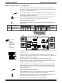
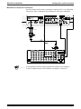
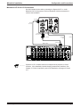
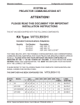
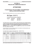
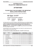
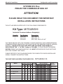
Mitsubishi Installation
Configuration and Connections
SYSTEM 8/10 Plus
PROJECTOR COMMUNICATIONS KIT
ATTENTION!
PLEASE READ THIS DOCUMENT FOR IMPORTANT
INSTALLATION INSTRUCTIONS
THIS KIT HAS BEEN SHIPPED WITH THE FOLLOWING COMPONENTS:
Kit Type: MITSUBISHI
Included Communications Adapter(s):
Quantity
1
1
1
Part Number
26-473-01
26-475-01
26-458-01
Description
ADP, UNV, “E”
ADP, UNV, “G”
ADP, UNV, “NEC-LCD MT”
THE TABLE BELOW LISTS THE POSSIBLE CONFIGURATION(S) AND CORRESPONDING
COMMUNICATIONS ADAPTER(S) FOR YOUR PROJECTOR MANUFACTURER’S VARIOUS
MODELS. PLEASE NOTE THAT YOUR SWITCHER HAS BEEN CONFIGURED AS
INDICATED BY THE “✔” IN THE “Config as” COLUMN. IF YOUR PROJECTOR MODEL
DIFFERS FROM THIS CONFIGURATION, YOU MUST RECONFIGURE YOUR SWITCHER
WITH THE CORRECT SETTINGS.
PLEASE REFER TO THE FOLLOWING PAGES FOR COMPLETE CONFIGURATION AND
SIGNAL CONNECTION INSTRUCTIONS.
THIS SWITCHER HAS BEEN CONFIGURED FOR:
Config
as
✔
Model
MITSUBISHI VS
Rotary Switches Cable
SW15 Settings
Comm
RS1 RS2 RS3 RS4 J2/J3 1 2 3 4 5 6 7 8 9 10 Adapter
VS
0
0
5
8
J2
↓ ↓ ↑ ↓ ↑ ↓ ↑ ↓ ↑ ↓ 26-473-01
LVP-X100
0
0
F
6
J2
↓ ↓ ↑ ↓ ↑ ↓ ↓ ↓ ↑ ↓ 26-475-01
LVP-X200/X300
1
0
F
6
J2
↓ ↓ ↑ ↓ ↑ ↓ ↓ ↓ ↑ ↓ 26-475-01
LVP-X400
3
0
F
6
J2
↓ ↓ ↑ ↓ ↑ ↓ ↓ ↓ ↑ ↓ 26-458-01
Extron • System 8/10 PLUS • User’s Manual • P/N 68-401-01 Rev. E
Page 1
Mitsubishi Installation
Configuration and Connections
Mitsubishi VS Projector Configuration
Verify that the System 8/10 PLUS is already configured for the Mitsubishi VS
projector. The general setup is explained on page 3-4 and the switch settings for
the projector are repeated below.
1. Use a small screwdriver to remove the access cover from the System 8/10 PLUS
front panel. See bottom of page 3-3. The label on the back of the access cover
also has the configuration information.
__________ Before changing anything, remove the AC power cord to the System 8/10 PLUS
to set the main power OFF; also turn the projector power OFF.
2. Set the switches as shown below:
____________ Be sure that SW15 (below) is set to Cable Saver mode (DIP switch #8 On), as
shown below.
Config
as
✔
Model
Mitsubishi VS
Rotary Switches Cable
RS1 RS2 RS3 RS4 J2/J3 1 2
0
0
5
8
3
SW15 Settings
4 5 6 7 8
↓ ↓ ↑ ↓ ↑ ↓
J2
ON
1
2
3
4
5
6
7
8
9 10
↑ ↓ ↑ ↓
9
Comm
Adapter
26-473-01
10
SW15 DIP Switch
RS2
_ RS5 is for
RGB
switching
delay. See
page 3-4 for
more
information.
RS3
RS5 RS2 RS1
RS1
RS4
RS3 RS4
Configured For:
RS-232
3. Use a grease pencil (or other rub-off marker) to mark the space on the label next
to “Mitsubishi VS”.
4. Locate the switcher’s Address DIP switches on the rear panel, lower right.
Unless this is part of a master/slave system, set #3 and #5 to the up position and
the others down. See picture to the left.
Use the illustration on the next page as a guide to the following steps.
5. Connect the Comm Adapter’s 9-pin male connector to the 9-pin female “Video
Switcher” connector on the rear panel of the projector.
6. Connect the CC-50' (or CC-100') cable from the 9-pin male connector of the
Comm Adapter to the 15-pin HD “Projector Control” port located on the rear
panel of the System 8/10 PLUS. (If you wish to make your own communications
cable, see page 3-2.)
______ Secure the screws on all D connectors.
7. Connect the BNC cables from the System 8/10 PLUS outputs to the Mitsubishi
VS projector inputs according to the application requirements.
8. Apply Main Power to the System 8/10 PLUS by connecting the power cord. The
Main Power LED should light. Apply power to the projector.
9. Return System 8/10 PLUS and projector to normal operation.
Extron • System 8/10 PLUS • User’s Manual • P/N 68-401-01 Rev. E
Page 2
Mitsubishi Installation
Configuration and Connections
Mitsubishi VS Projector Connections
Use the illustration below when connecting the System 8/10 PLUS to a Mitsubishi
VS projector. Refer to Mitsubishi documentation to continue the installation.
"E"
26-473-01
________ If the installation includes looping (master/slave) switchers, see Chapter 5.
If Video Loop Back is part of the installation, see pages 2-10 and 2-11.
Extron • System 8/10 PLUS • User’s Manual • P/N 68-401-01 Rev. E
Page 3
Mitsubishi Installation
Configuration and Connections
Mitsubishi LVP-X100 LCD Configuration
Check to see if the System 8/10 PLUS is already configured for the Mitsubishi
LVP-X100 projector. The general setup is explained on page 3-4 and the switch
settings for the LVP-X100 are repeated below.
1. Use a small screwdriver to remove the access cover from the System 8/10 PLUS
front panel. See bottom of page 3-3. The label on the back of the access cover
also has the configuration information.
__________ Before changing anything, remove the AC power cord to the System 8/10 PLUS
to verify that the main power is OFF; also turn the projector power OFF.
2. Set the switches as follows:
Config
as
Model
Rotary Switches Cable
RS1 RS2 RS3 RS4 J2/J3 1 2
Mitsu. LVP-X100
0
0
F
6
J2
SW15 Settings
4 5 6 7 8
↓ ↓ ↑ ↓ ↑ ↓
ON
_ RS5 is for RGB
switching delay. See
page 3-4 for more
information on switch
functions.
3
1
2
3
4
5
6
7
9 10
↓ ↓ ↑ ↓
8
9
Comm
Adapter
26-475-01
10
SW15 DIP Switch
RS2
RS3
RS5 RS2 RS1
RS1
RS4
RS3 RS4
Configured For:
RS-232
3. Use a grease pencil (or other rub-off marker) to mark the space on the label next
to “Mitsubishi LCD”.
4. Locate the switcher’s Address DIP switches on the rear panel, lower right.
Unless this is part of a master/slave system, set #3 and #5 to the up position and
the others down. See picture to the left.
Use the illustration on the facing page to do the following steps.
5. Plug the Comm Adapter’s 9-pin male connector into the 9-pin female “RS-232C”
connector on the side panel of the projector.
6. Connect the CC-50' (or CC-100') cable from the 9-pin male connector of the
Comm Adapter to the 15-pin HD “Projector Control” port located on the rear
panel of the System 8/10 PLUS.
______ Secure the screws on all D connectors.
7. Connect the BNC cables from the System 8/10 PLUS outputs to the
Mitsubishi X100 projector inputs according to the application requirements
(RGBHV and SVID/CVID).
8. Apply Main Power to the System 8/10 PLUS by connecting the power cord. The
Main Power LED should light. Apply power to the monitor.
9. Return System 8/10 PLUS and projector to normal operation.
Extron • System 8/10 PLUS • User’s Manual • P/N 68-401-01 Rev. E
Page 4
Mitsubishi Installation
Configuration and Connections
Mitsubishi LVP-X100 LCD Connections
Use the illustration below when connecting the System 8/10 PLUS to the
Mitsubishi LVP-X100 projector. Refer to Mitsubishi X100 documentation to
continue the installation.
15-Pin Male
SY-VGA
26-173-01
ComAdapter
26-475-01 "G"
G
Composite
Video
9-Pin Female
S-Video
15-Pin Male
RGBHV 5 BNC
________ System 8/10 PLUS channel numbers correspond to the projector’s “Group”
numbers. If the installation includes looping (master/slave) switchers, see
Chapter 5. If Video Loop Back is part of the installation, see pages 2-10 and
2-11.
Extron • System 8/10 PLUS • User’s Manual • P/N 68-401-01 Rev. E
Page 5
Mitsubishi Installation
Configuration and Connections
Mitsubishi LVP-X200 LCD Configuration
Check to see if the System 8/10 PLUS is already configured for the Mitsubishi
LVP-X200 projector. The general setup is explained on page 3-4 and the switch
settings for the LVP-X200 are repeated below.
1. Use a small screwdriver to remove the access cover from the System 8/10 PLUS
front panel. See bottom of page 3-3. The label on the back of the access cover
also has the configuration information.
__________ Before changing anything, remove the AC power cord to the System 8/10 PLUS
to verify that the main power is OFF; also turn the projector power OFF.
2. Set the switches as follows:
Config
as
Model
Rotary Switches Cable
RS1 RS2 RS3 RS4 J2/J3 1 2
Mitsu. LVP-X200
1
0
F
6
J2
SW15 Settings
4 5 6 7 8
↓ ↓ ↑ ↓ ↑ ↓
ON
_ RS5 is for RGB
switching delay. See
page 3-4 for more
information on switch
functions.
3
1
2
3
4
5
6
7
9 10
↓ ↓ ↑ ↓
8
9
Comm
Adapter
26-475-01
10
SW15 DIP Switch
RS2
RS3
RS5 RS2 RS1
RS1
RS4
RS3 RS4
Configured For:
RS-232
3. Use a grease pencil (or other rub-off marker) to mark the space on the label next
to “Mitsubishi LVP-X200”.
4. Locate the switcher’s Address DIP switches on the rear panel, lower right.
Unless this is part of a master/slave system, set #3 and #5 to the up position and
the others down. See picture to the left.
Use the illustration on the facing page to do the following steps.
5. Plug the Comm Adapter’s 9-pin male connector into the 9-pin female “RS-232C”
connector on the side panel of the projector.
6. Connect the CC-50' (or CC-100') cable from the 9-pin male connector of the
Comm Adapter to the 15-pin HD “Projector Control” port located on the rear
panel of the System 8/10 PLUS.
______ Secure the screws on all D connectors.
7. Connect the BNC cables from the System 8/10 PLUS outputs to the
Mitsubishi LVP-X200 projector inputs according to the application requirements
(RGBHV and SVID/CVID).
8. Apply Main Power to the System 8/10 PLUS by connecting the power cord. The
Main Power LED should light. Apply power to the monitor.
9. Return System 8/10 PLUS and projector to normal operation.
Extron • System 8/10 PLUS • User’s Manual • P/N 68-401-01 Rev. E
Page 6
Mitsubishi Installation
Configuration and Connections
Mitsubishi LVP-X200 LCD Connections
Use the illustration below when connecting the System 8/10 PLUS to the
Mitsubishi LVP-X200 projector. Refer to Mitsubishi LVP-X200 documentation to
continue the installation.
15-Pin Male
SY-VGA
26-173-01
ComAdapter
26-475-01 "G"
G
Composite
Video
9-Pin Female
S-Video
15-Pin Male
RGBHV 5 BNC
________ System 8/10 PLUS channel numbers correspond to the projector’s “Group”
numbers. If the installation includes looping (master/slave) switchers, see
Chapter 5. If Video Loop Back is part of the installation, see pages 2-10 and
2-11.
Extron • System 8/10 PLUS • User’s Manual • P/N 68-401-01 Rev. E
Page 7