1
TECHNICAL
Practice
1600A Series
Practice
TELECOM SOLUTIONS
FOR THE
ADA Compliant
Emergency Phones
2 1 S T C E N T U RY
June 13, 2006
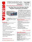
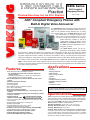
ADA* Compliant Emergency Phones with
Built-In Digital Voice Announcer
E-1600-02A
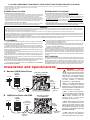
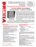
The 1600A Series ADA Compliant Emergency Phones are
designed to provide quick and reliable handsfree communication for any standard analog telephone line or analog
phone system station port. All 1600A Series phones meet
ADA requirements for elevator/ emergency telephones, and can be programmed from any Touch
Tone phone. The phones can dial up to 5 programmable emergency numbers, as well as 2
central station numbers. In addition, the E1600-20A and E-1600-52A feature a second "INFO" button that will dial up to 3 nonemergency numbers.
K-1600-EHFA
E-1600-45A
E-1600-03B
E-1600A
The 1600A Series phones can be programmed to automatically deliver a digital
announcement to identify the location of the emergency call. Alternatively, a DTMF Touch Tone code may also be
delivered. A “Call Connected” LED can be initiated manually or automatically. All programming parameters, including phone numbers and location numbers, are stored in non-volatile E2 memory. All units are phone line powered,
requiring no batteries or external power and are compatible with common Central Station Monitoring equipment.
E-1600-20A
E-1600-55A
For outdoor or harsh environments, select 1600A Series phones are available with Enhanced Weather Protection
(EWP). EWP products feature rubber gaskets and boots, hand soldered silicon sealed connections, gel-filled butt
connectors, as well as urethane potted circuit boards with weather sealed, field-adjustable trim pots and DIP switches for easy on-site programming.
Features
• Meets ADA requirements for Emergency Phones:
- Can automatically light the “Call Connected” LED for the
hearing impaired
- Transmits a unique location I.D. code or voice announcement
- Grade 2 Braille label for the visually impaired
• Non-volatile digital voice announcer with 16 seconds of voice
memory
• Advanced call progress detection
• Handsfree operation
• Phone line powered
• Non-volatile E2 memory (no batteries required)
• Touch Tone or pulse dialing
• Dials up to 5 emergency numbers
• E-1600-20A and E-1600-52A dial up to 3 non-emergency “INFO”
numbers
• Cycles through backup emergency and non-emergency numbers
on busy or no-answer
Need More Information on EWP?
• Optional Enhanced
? Call (715) 386-4345 and select 859.
Weather Protection (EWP)
• Hangs up on CPC, silence, busy signal, dial tone, time-out or Touch
Tone command
• Programmable to auto-answer on incoming calls
• Remotely programmable
• Extended temperature range (-15°F to 130°F)
• 7 different chassis or board only available
• Available in a 42” tall tower phone model E-1600A-BLT-EWP
• Central Station Monitoring capability (dials 2 numbers)
• Separate central station voice speed dial number
• Optional PB-100 Polling System available
• Optional BLK-3-EWP strobe light kit available
Applications
•
•
•
•
•
•
•
•
•
•
Elevators
Parking ramps/lots
ATM machines
Area of refuge locations
Lobbies
Entryways
Campus emergency stations
Roadside emergency stations
Stadiums
Convention centers
* Americans with Disabilities Act of 1992 contains federal regulations regarding elevator telephones (Public Law 101-336).
Specifications
Power: Telephone line powered. Minimum 24V DC talk battery voltage,
with a minimum loop current of 20mA loop (room temp), or 25mA (extended cold temp range). Loop current may be boosted on low current lines
with a Viking Model TBB-1 talk battery booster (Fax Back # 630).
Dimensions: See Installation and Specifications
Operating Temperature: -26° C to 54° C (-15° F to 130° F)
Humidity - Standard Products: 5% to 95% non-condensing
Humidity - EWP Products: Up to 100%
CAUTION - When installing on an analog extension of a phone system:
Some phone systems do not conform to analog telecom standards and might
not be compatible with the 1600A Series emergency phones. For a detailed
description of the telephone line specifications required for any of the 1600A
Series phones, retrieve Fax Back Document 869.
IF YOU HAVE A PROBLEM WITH A VIKING PRODUCT, PLEASE CONTACT: VIKING TECHNICAL SUPPORT AT (715) 386-8666
Our Technical Support Department is available for assistance Monday 8am - 4pm and Tuesday through Friday 8am - 5pm central time. So that we can give you better service, before you call please:
1. Know the model number, the serial number and what software version you have (see serial label).
2. Have your Technical Practice in front of you.
3. It is best if you are on site.
RETURNING PRODUCT FOR REPAIR
RETURNING PRODUCT FOR EXCHANGE
The following procedure is for equipment that needs repair:
1. Customer must contact Viking's Technical Support Department at 715-386-8666 to obtain a Return Authorization (RA)
number. The customer MUST have a complete description of the problem, with all pertinent information regarding the
defect, such as options set, conditions, symptoms, methods to duplicate problem, frequency of failure, etc.
2. Packing: Return equipment in original box or in proper packing so that damage will not occur while in transit. Static
sensitive equipment such as a circuit board should be in an anti-static bag, sandwiched between foam and individually boxed. All equipment should be wrapped to avoid packing material lodging in or sticking to the equipment. Include
ALL parts of the equipment. C.O.D. or freight collect shipments cannot be accepted. Ship cartons prepaid to:
Viking Electronics, 1531 Industrial Street, Hudson, WI 54016
3. Return shipping address: Be sure to include your return shipping address inside the box. We cannot ship to a PO Box.
4. RA number on carton: In large printing, write the R.A. number on the outside of each carton being returned.
The following procedure is for equipment that has failed out-of-box (within 10 days of purchase):
1. Customer must contact Viking’s Technical Support at 715-386-8666 to determine possible causes for the problem. The
customer MUST be able to step through recommended tests for diagnosis.
2. If the Technical Support Product Specialist determines that the equipment is defective based on the customer's input
and troubleshooting, a Return Authorization (R.A.) number will be issued. This number is valid for fourteen (14)
calendar days from the date of issue.
3. After obtaining the R.A. number, return the approved equipment to your distributor, referencing the R.A. number. Your
distributor will then replace the product over the counter at no charge. The distributor will then return the product to
Viking using the same R.A. number.
4. The distributor will NOT exchange this product without first obtaining the R.A. number from you. If you haven't
followed the steps listed in 1, 2 and 3, be aware that you will have to pay a restocking charge.
WARRANTY
Viking warrants its products to be free from defects in the workmanship or materials, under normal use and service, for a period of one year from the date of purchase from any authorized Viking distributor or 18 months from the date manufactured, which ever is greater. If at any time during the warranty period, the product is deemed defective or malfunctions, return the product to Viking Electronics, Inc., 1531 Industrial Street, Hudson, WI., 54016. Customer must contact Viking's
Technical Support Department at 715-386-8666 to obtain a Return Authorization (R.A.) number.
This warranty does not cover any damage to the product due to lightning, over voltage, under voltage, accident, misuse, abuse, negligence or any damage caused by use of the product by the purchaser or others.
Vikings sole responsibility shall be to repair or replace (at Viking's option) the material within the terms stated above. VIKING SHALL NOT BE LIABLE FOR ANY LOSS OR DAMAGE OF ANY KIND INCLUDING INCIDENTAL OR CONSEQUENTIAL DAMAGES RESULTING DIRECTLY OR INDIRECTLY FROM ANY BREACH OF ANY WARRANTY EXPRESSED OR IMPLIED, OR FOR ANY OTHER FAILURE OF THIS PRODUCT. Some states do not allow the exclusion or limitation of incidental or consequential damages, so this limitation may not apply to you.
THIS WARRANTY IS IN LIEU OF ALL OTHER WARRANTIES, EXPRESSED OR IMPLIED, INCLUDING THE WARRANTIES OF MERCHANTABILITY AND FITNESS FOR A PARTICULAR PURPOSE, WHICH ARE HEREBY EXCLUDED
BEYOND THE ONE YEAR DURATION OF THIS WARRANTY. Some states do not allow limitation on how long an implied warranty lasts, so the above limitation may not apply to you.
FCC REQUIREMENTS
This equipment complies with Part 68 of the FCC rules. Located on the equipment is a label that contains,
among other information, the FCC registration number and ringer equivalence number (REN). If requested, this
information must be provided to the telephone company.
The REN is used to determine the quantity of devices which may be connected to the telephone line.
Excessive REN's on the telephone line may result in the devices not ringing in response to an incoming call. In
most, but not all areas, the sum of the REN's should not exceed five (5.0) To be certain of the number of devices
that may be connected to the line, as determined by the total REN's, contact the telephone company to determine the maximum REN for the calling area.
This equipment cannot be used on the telephone company-provided coin service. Connection to Party Line
Service is subject to State Tariffs.
If this equipment causes harm to the telephone network, the telephone company will notify you in advance
that temporary discontinuance of service may be required. If advance notice isn't practical, the telephone company will notify the customer as soon as possible. Also, you will be advised of your right to file a complaint with
the FCC if you believe it is necessary.
The telephone company may make changes in its facilities, equipment, operations, or procedures that could
affect the operation of the equipment. If this happens, the telephone company will provide advance notice in
order for you to make the necessary modifications in order to maintain uninterrupted service.
If trouble is experienced with this equipment, please contact: Viking Electronics, Inc., 1531 Industrial
Street, Hudson, WI 54016 (715) 386-8666
If the trouble is causing harm to the telephone network, the telephone company may request you to remove
the equipment from the network until the problem is resolved.
The E-1600A Series phones use the USOC jack RJ11C.
It is recommended that the customer install an AC surge arrester in the AC outlet to which this device is connected. This is to avoid damaging the equipment caused by local lightning strikes and other electrical surges.
This equipment is Hearing-Aid Compatible (HAC).
The telephone Consumer Protection Act of 1991 makes it unlawful for any person to use a computer or other
electronic device, including fax machines, to send any message unless such message clearly contains in a margin at the top or bottom of each transmitted page or on the first page of the transmission, the date and time it is
sent and an identification of the business or other entity, or other individual sending the message and the telephone number of the sending machine or such business, other entity, or individual. (The telephone number provided may not be a 900 number or any other number for which charges exceed local or long-distance transmission charges.)
PART 15 LIMITATIONS
This equipment has been tested and found to comply with the limits for a Class A digital device, pursuant to Part
15 of the FCC Rules. These limits are designed to provide reasonable protection against harmful interference
when the equipment is operated in a commercial environment. This equipment generates, uses, and can radiate radio frequency energy and, if not installed and used in accordance with the instruction manual, may cause
harmful interference to radio communications. Operation of this equipment in a residential area is likely to cause
harmful interference in which case the user will be required to correct the interference at his own expense.
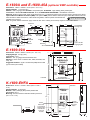
Installation and Specifications
C.O. Line
Rear View of a Standard
1600A Series Phone
*** Analog
PABX/KSU
Station
C.O.
Spade
Terminal
(included)
RJ11
or
** Earth Ground
(optional)
**** Drip Loop
(optional)
B. 1600A Series Phone with EWP
C.O. Line
Rear View of a 1600A
Series EWP Phone
Spade
Terminal
(included)
Red
und
)
2.
or
**** Drip Loop
(optional)
Green
* Note: The gel-filled (water-tight) butt
connectors are designed for insulation
displacement on 19-26 guage wire with a
maximum insulation of 0.082 inches. Do
not strip wires prior to terminating.
** Note: To increase surge protection,
loosen the PCB mounting screw labeled
vvvv(as shown) and fasten a wire with
spade terminal (included) from the
mounting screw to Earth Ground
(grounding rod, water pipe, etc.)
*** Analog
PABX/KSU
Station
* Gel-Filled
Butt Connectors
(included)
IMPORTANT:
Electronic
devices are susceptible to lightning and power station electrical
surges from both the AC outlet and the
telephone line. It is recommended that a
surge protector be installed to protect
against such surges. Contact Panamax
at (800) 472-5555 or Electronic
Specialists Inc. at (800) 225-4876.
!
A. Standard 1600A Series Phone
** Earth Ground
(optional)
*** Note: When installing a line powered
phone on a low voltage and/or low loop
current phone system extension, a PS2R Talk Battery/Loop Current boosting
power supply may be required. For more
information on the PS-2R, retrieve Fax
Back Documents 512.
**** Note: When wires are routed from
above, a “drip loop” is recommended to
keep water away from the circuit board.
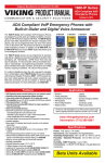
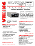
E - 1 6 0 0 A a n d E - 1 6 0 0 - 4 5 A (optional EWP available)
Dimensions: 133mm x 102mm x 51mm (5.25” x 4.0” x 2.0”)
Shipping Weight: 1.13 kg (2.5 lbs.)
Material: .062” (16 gauge) steel, E-1600A - Red powder paint, E-1600-45A - High visibility yellow powder paint
Connections: Standard E-1600A/E-1600-45A - RJ11, E-1600A-EWP/E-1600-45A-EWP - Gel-filled butt connectors
Mounting: Surface mount to walls, posts, single gang boxes or 4” x 4” electrical junction boxes or recess mount in elevator phone boxes.
Optional Enhanced Weather Protection (EWP): The optional EWP products feature sealed trim pots, sealed DIP switches, hand soldered and silicon sealed connections, rubber boots and gaskets, urethane potted circuit boards and
Need More Information on EWP?
? Call (715) 386-4345 and select 859.
gel-filled butt connectors.
Note: For greater weather resistance, apply a bead of clear silicon caulking around the top edge and sides of the chassis
3/4” Knock
Out
4.00
EMERGENCY
PHONE
5.25
MODEL E-1600A
CALL
CONNECTED
PUSH FOR
HELP
VIKING©
Bottom
View
Grade 2
Braille Label
Red Call
Connected LED
Push To
Call Button
3.40
2.00
2.00
(4) .20 diameter
mounting holes
E
M
E
R
G
E
N
C
Y
1.15
Condensation
Drain Hole
E-1600-45A
only
Side View
0.703
diameter
4.96
3.30
1.70
Rear View
(2) .20 x .40 slots
for single gang box
1.70
.15 x .31 wire exit notch
Front View
3.82
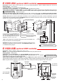
E-1600-02A
Dimensions: 330mm x 267mm x 51mm (13” x 10.5” x 2”)
Shipping Weight: 3.18 kg (7 lbs.)
Connections: RJ11
Material: .125” (11 gauge) brushed stainless steel
Mounting: Flush mount in elevator cabs, ATMs, stairwells, hallways, etc.
Suggested Hardware: (6) #8 x 3/4 flat head phillips sheet metal
type A screws (not included)
10.5
0.25
0.25
3.40
10.0
3.8
3.1
4.8
EMERGENCY
PHONE
6.25
13.0
Side
View
Minimum
Cutout
MODEL E-1600-02A
12.5
Red Call
Connected
LED
CALL
CONNECTED
PUSH FOR
Grade 2
Braille
Label
4.7
HELP
VIKING©
Push To
Call Button
(6) 0.188 diameter
countersunk holes
Front View
2.0
K - 1 6 0 0 - E H FA
Dimensions: 251mm x 174mm x 53mm (9.875” x 6.86” x
2.10”)
Shipping Weight: .91 kg (2 lbs.)
Material: .062” (16 Gauge) Red powder painted steel
Connections: RJ11
Mounting: Recess mounted in standard elevator phone box
(10.0” x 7.0” x 3.0”)
Front View
EMERGENCY
PHONE
MODEL K-1600-EHFA
8.50
9.875
CALL
CONNECTED
Grade 2
Braille Label
Top View
(2) countersunk
mounting holes
for #8 flat head
screws (not
included)
PUSH FOR
HELP
Red Call
Connected LED
Push to Call
Button
Side
View
VIKING©
0.675
VIKING ©
1.60
0.70
2.10
6.86
3.
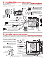
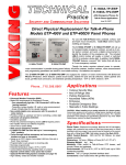
E - 1 6 0 0 - 2 0 A (optional EWP available)
Dimensions: Overall - 127mm x 127 x 57mm (5.0” x 5.0” x 2.25”), Plastic Electrical Box - 102mm x 102mm x 54mm (4.0” x 4.0” x 2.14”)
Shipping Weight: 1 kg (2.12 lbs.)
Front Panel Material: 14 gauge brushed stainless steel
Connections: Standard E-1600-20A - RJ11, E-1600-20A-EWP - Gel-filled butt connectors
Optional Enhanced Weather Protection (EWP): The optional EWP products feature sealed trim pots, sealed DIP switches, hand soldered and silicon sealed connections, rubber boots and gaskets, urethane potted circuit boards and gelNeed More Information on EWP?
? Call (715) 386-4345 and select 859. filled butt connectors.
Mounting with Plastic Rough-In Box (included): Flush into walls, mounts to side of wall stud Mounting with Optional VE-5x5:
Surface mount to walls, single gang boxes, double gang boxes, posts, or to a Viking VE-GNP Gooseneck pedestal (see options below).
Caution: When warm air comes in contact with cold surfaces, such as outside walls and conduits, it causes condensation. To prevent
condensation from accumulating inside the E-1600-20A always bring conduit into the bottom of the unit. If this is not possible, drill a 1/4”
diameter hole in the bottom of the black plastic box.
2.1”
Front View of
Plastic Rough-In
Box (included)
10.50”
* Adhere gasket to front panel,
centering over mounting holes
4.0"
3.25”
5.22”
3.81”
Y
Wall Stud
NC
RGE
EMEHONE
P
5.0”
Condensation
Drain Hole
5.14”
P
HEL
INFO
3/4" Knockout
for conduit
Grade 2 Braille
Label
Front View of Optional
VE-5x5 (not included)
L
CALCTED
NE
CON
Wire knock out
"Help" Push to
Call Button
(2) Standard flat head dry wall
(sheet rock) screws (not included)
The black plastic rough-in box (part # 259576) may be
purchased separately (Example: Mounting boxes to
studs before the walls are finished for flush installation). Go to www.vikingelectronics.com and click on
“Spare Parts” to order these rough-in boxes.
2.25”
39.5”
(4) 0.38” diameter
Call Connected
Red LED
(4) 0.2 x 0.43 slots
for double gang box
"Info" Push to Call Button
(2) 0.2 x 0.43 slots
for single gang box
(4) 6-32 X 3/4” stainless steel, flat
head, hexdrive, screws (included)
41.41”
Condensation Drain Hole
* Note: Peel off paper liner and adhere gasket to the back of the faceplate, centering it over the four corner mounting holes.
3.0” 3.3”
3/4"
Knockout
3.0”
Important: Be careful to position the modular jack inside the chassis as not to
damage the components on the circuit board. The E-1600-20A will NOT mount
to a standard double gang box.
Rear View of VE-5x5
(not included)
?
Side View of VE-GNP
(not included)
Need More Information on the VE-5x5 or VE-GNP?
Call (715) 386-4345 and select 424.
E - 1 6 0 0 - 0 3 B (optional EWP available)
Dimensions: 183mm x 149mm x 39mm (7.22” x 5.86” x 1.55”)
Material: .074” (14 gauge) Brushed stainless steel panel and extra heavy duty button with LED
Shipping Weight: 1.36 kg (3 lbs.)
Connections: Standard E-1600-03B - RJ11, E-1600-03B-EWP - Gel-filled butt connectors
Need More Information on EWP?
Mounting: Surface mount to walls, posts, single gang boxes, double gang boxes or 4” x 4” electrical
? Call (715) 386-4345 and select 859.
junction boxes or recess mount in elevator phone boxes.
Optional Enhanced Weather Protection (EWP): The optional EWP products feature sealed trim pots, sealed DIP switches, hand soldered and silicon sealed connections, rubber boots and gaskets, urethane potted circuit boards and gel- filled butt connectors.
Note: For greater weather resistance, apply a bead of clear silicon caulking around the top edge and sides of the chassis
Front View
Back View
Condensation
Drain Hole
5.36
EMERGENCY
PHONE
(4) .22 diameter
mounting holes
1.69
1.55
Grade 2
Braille Label
PUSH FOR
HELP
VIKING©
0.781
dia.
1.70
7.22
Bottom View
3.40
3.30
6.78
CALL
CONNECTED
Call Connected LED
VIKING ©
MODEL E-1600-03B
0.80
4.
(4) .187 x .50
slots for double
gang box
0.795
Push To Call Button
8-32 x .5" set
screws provided
1.70
2.605
3.40
5.00
(2) .187 x .50
slots for single
gang box
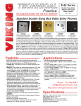
E - 1 6 0 0 - 5 0 A / 5 2 A (optional EWP available)
Note: This is a 1600A parts kit without chassis.
Shipping Weight: .45 kg (1 lb)
Connections: Standard E-1600-50A/52A - RJ11, E-1600-50AEWP/52A-EWP - Gel-filled butt connectors
Optional Enhanced Weather Protection (EWP): The optional EWP products
feature sealed trim pots, sealed DIP switches, hand soldered and silicon
sealed connections, rubber boots and gaskets, urethane potted circuit boards
and gel-filled butt connectors.
?
(2) 0.10 diameter
mounting holes
(4) 0.335 x 0.177
mounting slots
for #4 or #6 studs
Side
View
.47 .785
2.60
2.10
0.827
Mic Hole
2.37
Mylar Speaker Dimensions
Black
Side View
PC Board Mounting
Red
3.54
3.20
Gel-filled butt
connectors
(EWP only)
Connect to phone line
(E-1600-50A-EWP/52A-EWP)
Connect to phone line
(standard E-1600-50A/52A)
Panel
-or-
Screen (included)
Speaker Gasket
(EWP only)
Note: Mic holes should be near the bottom of the boot to allow for drainage.
EWP Mic Mounting Boot. Glue to the
back of your panel at an upward angle
(shown left) behind a 0.10” - 0.25” diameter hole.
2.10
1.0
Speaker
(included)
Standard Mic Mounting Boot. Glue or
screw directly behind 0.04” - 0.125” diameter hole in panel.
.50
2.60
Cone
Dia.
Need More Information on EWP?
Call (715) 386-4345 and select 859.
0.5
-or-
Red
Green
RJ11
1.50
Red
2.95
Connect to “INFO” button (E-1600-52A only,
requires a .75” diameter mounting hole)
Red
Red call connected LED with
mounting hardware (requires a
.250” diameter mounting hole)
0.80
Maximum
0.17
EWP
version
is hand
soldered
Red (LED anode)
0.95
Black (LED cathode)
Clear Spacer Red Retaining
Lens
LED
Ring
Connect to “PUSH FOR HELP” or “HELP” button
(requires a .75” diameter mounting hole).
Black
Note: When using the included push button
switches, cut off forked portion of spade lugs and
fasten screws to barrel portion of spade lugs.
Black
2.20
PUSH FOR
Spade
Terminal
(included)
These (2) mounting
holes are not available
on EWP models
HELP
VIKING©
(4) 0.156 diameter
mounting holes
2.40
* Earth Ground
(optional)
BL-1 grade 2 black
braille label included
Important: If installing the EWP version outdoors, apply non-corrosive silicone (included with EWP version) to back side of LED and push button switches
after making all connections and testing. Completely encapsulate exposed switch connections (screw terminals/stripped wires) and bare wire connections.
E-1600-55A
(optional EWP available)
The E-1600-55A is a universal emergency phone kit for installing behind elevator panels, or an installation requiring a custom panel. The finished panel
should provide: (4) studs (#6 diameter minimum) for mounting plate, audio holes for speaker and microphone, a momentary SPST push button switch and
a 0.25” diameter mounting hole for the LED. Alternatively, the LED can be cut off and the wires connected to a integral switch with LED (often found in
elevators). Note: An LED must be connected to the red and black wires for the phone to operate.
Optional Enhanced Weather Protection (EWP):
The optional EWP products feature sealed trim
pots, sealed DIP switches, hand soldered and silicon sealed connections, rubber boots and gaskets,
urethane potted circuit boards and gel-filled butt
connectors.
Need More Information on EWP?
?
4.50
Connect to
phone line
(EWP version)
Gel-filled butt
connectors
(EWP only)
Connect to
phone line
(standard
version) RJ11
-or-
2.25
Red
Green
2.1”
4.0"
Red "Call Connected" LED with
included mounting hardware
(requires a 0.25" diameter hole)
Red (LED
anode)
Clear Spacer Red 5mm Retaining
Lens
Round LED Ring
Connect to momentary push
button switch with contact
rating of 50VDC/100mA min
5.0
Black (LED
cathode)
3.77
Black
4.50
*
Black
Additional wire length may be
added if required.
0.25
Diameter
(4) Countersunk holes for
mounting the dust cover
(4) 0.25 diameter clearance holes
for mounting the unit to the back
side of a finished panel.
Wire
Knockout
3.625
Typ.
*
* Note:
Dust Cover Install prior to fastening
faceplate to finished panel.
1.76
2.0
Diameter
Call (715) 386-4345 and select 859.
Shipping Weight: .73 kg (1.6 lb)
Connections: Telco - RJ-11 jack or wire
nuts, Switch - spade terminals
Material: 0.062” thick (16 gauge) zinc
plated steel
0.25 Typ.
(4) 6-32 x 3/4" stainless steel flat head, hexdrive,
screws (included) for fastening dust cover
5.0
1/16" thick foam gasket (included) for accoustically sealing
mic and speaker to back of finished panel. Remove backing
and adhere gasket to front panel of the E-1600-55A,
centering over speaker and microphone holes (as shown).
(4) 0.25 diameter
holes (not used)
Stainless steel speaker and
microphone protection screens
5.
Programming
A. Accessing the Programming Mode
The 1600A Series emergency phones can be programmed from any Touch Tone
phone using a C.O. line, analog PABX/KSU station, or a DLE-200B Line Simulator.
?
Need More Information on the DLE-200B?
Call (715) 386-4345 and select 605.
1. Using the Security Code
Step 1. Move DIP switch 2 to the ON position (sets unit to answer incoming calls, see section J).
Step 2. From a Touch Tone phone call the line attached to the 1600A Series phone.
Step 3. When the 1600A Series phone answers, enter the 6-digit security code (factory set to 845464, see section C). A
double beep should then be heard indicating you have entered the programming mode.
2. Without the Security Code
Step 1. Move DIP switch 2 to the ON position (sets unit to answer incoming calls, see section J).
Step 2. Move DIP switch 3 to the OFF position (incoming calls enter Programming without security code, see section J).
Step 3. From a Touch Tone phone call the line attached to the 1600A Series phone.
Step 4. When the 1600A Series answers, a double beep will be heard and will automatically enter the programming mode.
Step 5. When finished programming, move DIP switch 3 back to the ON position (see section J).
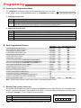
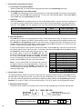
B. Quick Programming Features
Enter Digits - then - Enter Memory Location
First emergency speed dial number ......................................................................... 0-20 digits
Second emergency speed dial number ................................................................... 0-20 digits
Third emergency speed dial number ....................................................................... 0-20 digits
Fourth emergency speed dial number ..................................................................... 0-20 digits
Fifth emergency speed dial number ......................................................................... 0-20 digits
Central station receiver number ............................................................................... 0-20 digits
Central station voice number ................................................................................... 0-20 digits
First “Info” speed dial number (E-1600-20A and E-1600-52A only) ......................... 0-20 digits
Second “Info” speed dial number (E-1600-20A and E-1600-52A only) .................... 0-20 digits
Third “Info” speed dial number (E-1600-20A and E-1600-52A only) ........................ 0-20 digits
Voice announcer options (factory set to 000000) ..................................................... 6 digits
Timing/Dialing options (factory set to 234111) ......................................................... 6 digits
Security code (factory set to 845464) ...................................................................... 6 digits
Identification number (factory cleared) .................................................................... 0-20 digits
To add a 4 at any point in the dialing string .............................................................. 44
To add a # at any point in the dialing string .............................................................. 4#
To add a four second pause at any point in the dialing string ................................... 47
To switch to pulse dialing at any point in the dialing string ........................................ 46
To clear any speed dial number ............................................................................... (no digits)
then
then
then
then
then
then
then
then
then
then
then
then
then
then
then
#00
#01
#02
#03
#04
#05
#06
#07
#08
#09
#17
#18
#19
#20
#00 - #09
Note: A double beep indicates a valid memory position, four beeps indicate an error.
C. Security Code (memory location #19)
The security code allows the user/installer to program the 1600A series phone while DIP switch 3 is in the ON (normal)
position. The factory set security code is 845464 (V-I-K-I-N-G). It is recommended that the factory set security code
be changed. Example: To store 123456 as the security code:
Step 1. Access programming as shown is Programming section A.
Step 2. Enter 123456 #19..
Step 3. Hang-up.
Note: The security code must be 6 digits and cannot include a 4 or a #.
6.
Enter Your Security Code Here:
#19
D. Speed Dial Numbers
Note: Up to 20 digits can be stored in each dial position. Special features such as pause, mode change, Touch Tone
4 and # count as single digits.
1. Emergency Speed Dial Numbers (memory locations #00 - #04)
The emergency speed dial number programmed in location #00 is the number that
is dialed when the “HELP” / ”CALL” button is first pressed. Additional speed dial
numbers will be dialed when there is no answer or a busy signal is detected and the
next number redial features are activated. To program, enter the desired speed dial
number followed by the location number (#00 - #04). To clear a speed dial location,
simply enter the memory location (#00 - #04) alone. The 1600A series phone is
factory set with no speed dial number programmed.
To Program:
Enter:
4
44
#
4#
4 second pause
47
switch to pulse mode
46
0, 1, 2...9
0, 1, 2...9
2. “INFO” Speed Dial Numbers (E-1600-20A/52A Only) (memory locations #07 - #09)
The information speed dial number programmed in location #07 is the telephone or extension number that is dialed
when the “INFO” button is first pressed. Additional information speed dial numbers will be dialed when there is no
answer or a busy signal is detected and the next number redial features are activated. The E-1600-20A phone will
cycle through the programmed speed dial numbers until answered. To program, enter the desired speed dial number followed by the location number (#07 - #09). To clear a speed dial location, simply enter the location (#07 - #09)
alone.
3. Speed Dial Programming Examples
Step 1 See Section A
Step 2 - Enter Digits:
...to store 555-1234 as the first emergency speed dial number
Enter Programming
5551234#00
...to store a Touch Tone 9, a four second pause and then a pulse
dialed 333-4444 into the second “Info” speed dial memory position
Enter Programming
9 47 46 3 3 3 4 4 4 4 # 0 8
...to clear the first emergency speed dial number
Enter Programming
#00
To Program the 1600A Series Phone...
E. Identification Number (memory location #20)
The Touch Tone I.D. number (up to 20 digits) is used by emergency personnel to identify the location of the caller and
is given out when the receiving party presses a Touch Tone 4. The security office can display the number using a
Touch Tone decoder. To program the I.D. number, enter the desired number followed by #20. Example: To store 333
as the I.D. number, enter: 3 3 3 # 2 0
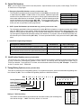
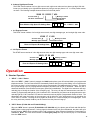
F. Timing/Dialing Options (memory location #18)
There are six positions in the timing/dialing options. To program these options, enter the six desired timing/dialing numbers followed by #18. The six available timing/dialing options are defined as follows:
Dial: A + B + C + D + E + F + # + 1 + 8
Factory Default Setting: 2 + 3 + 4 + 1 + 1 + 1
Enter Timing/Dialing Settings Here:
A
B
Talk/Listen Delay
Call Length
Silence Time Out
Dial Next Number on Ring No Answer
Dial Next Number on Busy
Pulse Dial Speed
Setting A - Talk/Listen Delay
This feature selects switching time between talk and listen modes (VOX switching time).
Use chart at the right. * Note: The factory default is .2 seconds.
C
D
E
F
#18
Touch
Tone
1
2
3
4
5
6
7
8
9
Talk/Listen
Delay
.1 sec
.2 sec *
.3 sec
.4 sec
.5 sec
.6 sec
.7 sec
.8 sec
.9 sec
7.
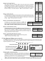
Setting B - Call Length Time Out
This feature selects the maximum length of time that calls can be connected.
Programmable in increments of 1 minute up to a maximum of 9 minutes (Touch Tones 1 9). Program 0 in this location to disable the call length time out. With the call length disabled, the 1600A series phone must rely on a CPC signal, busy signal, silence or return to
dial tone to hang-up. Use chart at the right. * Note: The factory default is 3 minutes.
Setting C - Silence Time Out
This feature selects the length of time that calls will remain connected without voice activity. Programmable in increments of 10 seconds up to a maximum of 90 seconds (Touch
Tones 1 - 9). To disable the silence time out, program 0 in this location. Use chart at the
far right. * Note: The factory default is 40 seconds.
Setting D - Dial Next Number on Ring No Answer
If enabled and a ring-no-answer is detected, the 1600A series
phone will dial the next programmed speed dial number, and continue to cycle through the emergency numbers until a call is completed. * Note: This feature is disabled in the factory default setting.
Touch
Tone
0
1
2
3
4
5
6
7
8
9
Call Length
Time Out
Disabled
1 min
2 min
3 min*
4 min
5 min
6 min
7 min
8 min
9 min
Touch
Tone
0
1
2
3
4
5
6
7
8
9
Silence
Time Out
Disabled
10 sec
20 sec
30 sec
40 sec*
50 sec
60 sec
70 sec
80 sec
90 sec
Setting D
Disabled*
Dials second number after
2, 3, 4...9 rings respectively
Touch Tone
1 or 0
2, 3, 4...9
Setting E - Dial Next Number on Busy
If enabled and a busy is detected, the 1600A series phone will dial the next programmed speed dial number, and continue to cycle through the emergency numbers until a call is completed. * Notes: This feature is disabled in the factory
default setting. If the busy signal is interrupted with a promotional message, contact your central office to have it removed.
Touch Tone
1
2
Setting E
Disabled*
Enabled
Touch Tone
1
2
Setting F
10 pps*
20 pps
Setting F - Pulse Dialing Rate (Pulses per second)
The 1600A series phone is capable of different pulse dialing speeds.
* Note: The factory default setting is 10pps.
G. Voice Announcer Options (memory location #17)
The 1600A series phones have a built-in non-volatile digital voice announcer that may be used to identify the location
of the emergency phone call. The 16 seconds of digital record time is recorded remotely from a Touch Tone phone.
Programming options are as follows:
Dial: A + B + C + D + E + F + # + 1 + 7
Factory Default Setting: 0 + 0 + 0 + 0 + 0 + 0
Two Digit Announcement Delay {
Enter Settings Here:
A
B
C
Repeat Announcement Setting
D
E
F
0
0
0 #17
Future Use (enter “0”)
Settings A and B - Announcement Delay
The 1600A series phone is factory set to automatically start playing the
voice announcement after it has determined the call has been answered.
Alternately, the announcement may be programmed to play after a programmed amount of time, from 1 to 99 seconds after dialing.
8.
Touch Tone
00
01-99
Setting A/B
Play automatically
1-99 seconds*
* Note: If the announcement delay time is used, you must allow enough time for the 1600A series phone to detect
ring-no-answer and busy signals when using the redial features. The factory default is set to play automatically.
Setting C - Repeat Announcement Option
The 1600A can be programmed to play the announcement from 1-9 times,
or to continuously repeat the announcement every 8 seconds until a
Touch Tone 4 is detected from the distant party. The I.D. number (if programmed) will be sent and the call connected LED will turn on automatically after the announcement has stopped repeating.
Touch Tone
0
1-9
Setting C
Repeat every 8 secs*
Repeat 1-9 times
* Note: The factory default for the 1600A series phone is to repeat until a 4 is detected (digit 0).
H. Recording the Announcement
Step 1. Call into the 1600A series phone with a Touch Tone phone and access programming.
Step 2. Enter 44, wait for the tone and then begin recording. Sixteen seconds of record time is available.
Step 3. Enter any Touch Tone to stop the recording. Playback is automatic.
Step 4. Enter 45 to review the announcement again.
Step 5. If you choose to not use a voice announcement, enter 43 to clear the recording.
Example: “Elevator number 1215, located in the Financial Building, needs assistance. Press the asterisk (4) key on
your telephone to start and stop this announcement...”
I. Automating the Call Connected LED
There are two methods of turning on the Call Connected LED. The LED will turn on after a Touch Tone 4 is detected
from the distant party or after the voice announcer is finished playing a programmed number of times. If you want the
Call Connected LED to light automatically when the call has been answered, but you don’t want a voice announcement
to be played, follow these programming steps:
Step 1:
Step 2:
Step 3:
Access Programming as shown in section A
Make a short (1 second) recording of silence
Enter digits: 001000#17
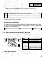
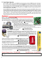
J. DIP Switch Programming/Speaker and Microphone Adjustments
Two POTs are provided to increase or decrease speaker volume and microphone sensitivity. In certain noisy locations
the microphone sensitivity may need to be decreased as shown below. Caution: Setting the microphone gain too high
may cause distorted audio, prevent the distant party from breaking over and inhibit second number redialing.
Speaker
Volume
Microphone
Sensitivity
DIP Switches
Off
1
2
3
On
(DIP Switches shown
in factory setting)
DIP
Position Description
Switch
ON
“HELP” / “CALL” button alternately connects
1
and disconnects calls (factory default)
OFF
“HELP” / “CALL” button connects calls only
2
ON
Incoming calls answered (factory setting)
2
OFF
Incoming calls are not answered
3
ON
Normal operation mode (factory setting)
3
OFF
Learn mode - Any incoming calls are automatically entered into the programming
mode (no security code required). Use this
option if you have forgotten your security
code.
1
K. Central Station Programming
The standard 1600A emergency phone is capable of communicating using the “Ademco Contact I.D.”, “Ademco High
Speed”, “DTMF 4+1 Express”, or the “DTMF 4+2 Express” formats. All formats use the programming memory location
#20 to store the account code and alarm details.
9.
1. Central Station Programming Features
a. Accessing the Programming Mode
Before programming, you must access the programming mode (see Programming section A).
b. Enabling/Disabling Central Station Mode
The 1600A Series emergency phone can be placed in the “Central Station Mode” by entering a central station
phone number in position #05 while programming. To cancel the “Central Station Mode,” clear position #05 by
entering #05 only (see Programming section D).
c. Ring Delay
When the 1600A Series emergency phone is in the “Central Station Mode”, it is best to have the ring delay set
to a minimum of three, because some receivers send a long tone after answering the line that sounds like a
ring back. If the 1600A is set to a ring delay of two, the phone will disconnect (see Programming section F).
To Program the 1600A Series Phone...
Step 1:
Step 2 - Enter Digits:
...to enable central station programming and dial 952-2567
Enter Programming
9522567#05
...to disable central station programming
Enter Programming
#05
d. Speed Dial Numbers
The 1600A Series phone can be programmed to dial a central station receiver only, or dial up to 5 voice numbers first, and if no answer, then dial the central station receiver. When calling the first numbers (memory positions #00-#04 (see Programming section D), the phone stays in “two-way talk mode” allowing two-way conversation. When calling the Central Station number (memory position #05), the phone is in a “listen only mode”
in order to interpret the hand shake signals of the receiver.
A second central station number position has been provided in location #06 that is used when the central station receiver does not have a talk over mode. If a number is placed in position #05 and position #06 is cleared,
the E-1600A will call the central station monitor receiver. After
the receiver sends a kiss-off, the E-1600A lights the “Call
Location Call Type
Connected” LED and goes into two-way talk mode. If numbers
#00
Voice - Emergency
are in both positions #05 and #06, the E-1600A will call the
Voice - Emergency
#01
receiver first, and after the kiss-off, will hang-up and redial the
Voice - Emergency
#02
number in position #06 for two-way voice communication
#03
Voice - Emergency
Notes: If only a central station is to be dialed, the central station phone number must be preprogrammed in memory location #05 and memory locations #00-#04 must be cleared. The
“Call Connected” LED will light automatically if there is a voice
recording programmed.
#04
#05
#06
#07
#08
#09
Voice - Emergency
Central Station Receiver
Central Station Voice Line
Voice - “Info” (E-1600-20A/52A only)
Voice - “Info” (E-1600-20A/52A only)
Voice - “Info” (E-1600-20A/52A only)
2. Central Station Formats
The following examples explain the receiver formats and how to properly program memory location #20. Each format starts with a four digit account code. This is the code that is assigned by your central station for billing purposes. You must access the programming mode before programming these features (see Programming section A).
Important: If a number is shown, you must use that number. If an “X” is shown, use any appropriate number.
a. Ademco Contact ID Format
This DTMF format consists of a four digit account code, two digit message type, and a nine digit data field.
XXXX 18 1 14000 XXX #20
Account Code
Message Type
New Event
Enter Contact ID Settings Here:
10.
Memory Location
Any number to identify phone
General Alarm
18 1 14000
#20
b. Ademco High Speed Format
This DTMF format consists of a four digit account code, eight zone codes and one alarm type digit. With this
format you can identify up to eight different phones by using a zone per phone. A “5” in a zone position means
no alarm. The following example shows an alarm from the third phone.
XXXX 55 1 55555 7 #20
Memory Location
Normal Alarm
New Event
Account Code
Idle Zone
Enter Ademco High Speed ID Settings Here:
55 1 55555 7 #20
c. 4+1 Express Format
This DTMF format consists of a four digit account code, two digit message type, and a single digit event code.
XXXX 17 X #20
Account Code
Message Type
Enter 4+1 Express ID Settings Here:
Memory Location
Event Code
17
#20
d. 4+2 Express Format
This DTMF format consists of a four digit account code, two digit message type, and a two digit event code.
XXXX 27 XX #20
Account Code
Message Type
Enter 4+2 Express ID Settings Here:
Memory Location
Event Code
27
#20
Operation
A. Standard Operation
1. “HELP” / “CALL” Button
When the “HELP” / “CALL” button is pressed, the 1600A series phone goes off-hook and dials a pre-programmed
telephone number. The Call Connected LED momentarily flashes during tone or pulse dialing. In the event that the
line is busy or there is a ring-no-answer, the unit can be programmed to call additional phone numbers. The phone
then cycles through up to 5 pre-programmed emergency numbers until the call is answered. When the call is
answered, handsfree communication to emergency personnel is established. The digital voice announcer will automatically play to identify the location of the emergency call. The 4 key will stop the announcement, send the I.D.
number (if programmed) and light the “Call Connected” LED. Alternatively, the phone can be programmed to automatically light the “Call Connected” LED after the announcement has played a programmed number of times. The
distant party will know the location of the emergency call by either the voice announcement or by decoding the
Touch Tone I.D. number. Pressing the 4 key again will send the I.D. number and play the message again. Once
the 4 key has been pressed, the # key can be used to force the phone to hang-up.
2. “INFO” Button (E-1600-20A and E-1600-52A Only)
When the “INFO” button is pressed (E-1600-20A and E-1600-52A only), the phone goes off-hook and dials the first
“INFO” phone number programmed. If a busy signal is detected or the call goes unanswered, the phone will cycle
through all three “INFO” phone numbers until the call is answered. When answered, handsfree communication is
established. Note: The voice announcement is for Emergency/Help calls only and will not play on a call initiated
from the “INFO” button.
11.
B. Central Station Operation
After the “HELP” / “CALL” button on the 1600A Series phone has been pressed the 1600A Series phone will begin to
dial. If a voice number is programmed in memory locations #00-#04, these numbers will be dialed first. Upon detecting a busy signal or after a preprogrammed ring delay the 1600A Series phone will hang-up and dial the central station phone number stored in memory location #05. When the central station receiver answers, it will send a handshake
tone to the 1600A phone. Upon detecting the handshake tone, the 1600A Series phone will begin uploading the information stored in memory location #20.
Once the 1600A Series emergency phone has sent the information stored in memory location #20, it waits for a “kissoff” tone from the central station. When the “kiss-off” tone is received, the emergency phone turns on the call connected LED and goes into the “two-way talk mode” or hangs up and dials position #06 if programmed. Note: The central
station should have a “talk-over” feature that will allow a two way conversation at this time. If your receiver does not
support a “talk-over”. A voice phone number should be programmed into position #06. If the central station answers
the call and does not send a “kiss-off”, the next number will be dialed (if programmed). In either single number or multinumber programming, the phone will keep dialing until a call is completed.
Options
Enhanced Weather Protection (EWP)
Some applications demand the extra protection of EWP. For example: phones that are exposed to the elements, a corrosive atmosphere, or vehicle exhaust all need the extra weather and corrosion resistance of
EWP. EWP is available on the following Viking models: E-1600A, E-1600-03B, E-1600-20A, E-1600-45A,
E-1600-50A, E-1600-52A/55A, K-1700-3,
Need More Information on EWP?
? Call
(715) 386-4345 and select 859.
E-1600A-BLT-EWP and BLK-3-EWP.
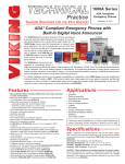
PB-100
System
PB-100 Polling and Diagnostics Kit
The PB-100 system provides centralized polling and diagnostics of all Viking 1600 and 1600A
series emergency phones through a standard Windows 9x/NT P.C. In addition, any device or
human capable of returning DTMF Touch Tones can be automatically polled.
Up to 500 individual phones can be polled, at timed intervals, for the diagnosis of proper programming and operation.
Need More Information on the PB-100?
?
Call (715) 386-4345 and select 860.
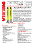
BLK-3-EWP Strobe Light Kit
The BLK-3-EWP can be used to add emergency notification to pre-installed emergency phones. The
BLK-3-EWP is equipped with Enhanced Weather Protection (EWP) and will not flash on “Info” calls
when used with the E-1600-20A or E-1600-52A. Alternatively, the BLK-3-EWP provides high visibility indication of analog line status through a high powered strobe light. The BLK-3-EWP is an ideal
solution for the hearing impaired and can be used equally well in loud warehouses or factories, where
ringing phones can not be heard.
Need More Information on the BLK-3-EWP?
?
BLK-3-EWP
Call (715) 386-4345 and select 653.
Special Housing
A variety of special housing is available for the 1600A Series emergency phones. The VE5x5 surface mount backbox may be used with the E-1600-20A-EWP to allow surface mounting or mounting to a gooseneck pedestal.
Need More Information on the VE-5x5?
?
Call (715) 386-4345 and select 424.
The weatherproof VE-9x12 may be used with the E-1600A, E-1600-03B, E-1600-20A and E1600-45A for extreme weather and vandal protection.
Need More Information on the VE-9x12?
? Call (715) 386-4345 and select 413.
The VE-9x12 is available in yellow or red.
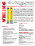
42” Tall ADA Tower Phone with Integrated Blue Strobe Light
VE-9x12
Provide added safety for your patrons, employees, and students with the addition of high-visibility, ADA Compliant emergency communication. At the push of a button, the E-1600A-BLT-EWP (shown right) will initiate a call to your emergency
personnel and send a digital announcement to identify the location of the emergency call. In addition, the Tower Phone’s
bright (1million candle power) Strobe Light will instantly begin pulsating to deter further activity and make it fast and easy
for Police or Security personnel to locate the site of the emergency. The phone comes complete with Enhanced Weather
Protection (EWP), as shown above.
Need More Information on the E-1600A-BLT-EWP?
?
Call (715) 386-4345 and select 217.
Product Support Line...715.386.8666
E-1600A-BLT-EWP
Fax Back Line...715.386.4345
Due to the dynamic nature of the product design, the information contained in this document is subject to change without notice. Viking Electronics, and its affiliates and/or
subsidiaries assume no responsibility for errors and omissions contained in this information. Revisions of this document or new editions of it may be issued to incorporate
such changes.
Fax Back Doc 215
12.
Printed in the U.S.A.
ZF301710 Rev G