1
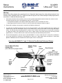
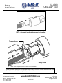
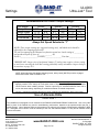
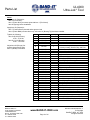
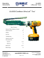
Operating Instructions UL4000 Ultra-Lok Tool UL4000 Cordless Ultra-Lok Tool Table of Contents Warranty, Safety Guidelines, Contents Setup Instructions 2 3-4 Settings 5 Parts List 6 Troubleshooting 7 Assembly Instructions 8 Clamp Application Free-End Preformed Maintenance Blade Change BAND-IT-IDEX, Inc. A Unit of IDEX Corporation 4799 Dahlia Street Denver, CO 80216-0307 USA P: 1-800-525-0758 F: 1-800-624-3925 9-10 11 12-13 14 www.BAND-IT-IDEX.com Page 1 of 14 Document # P07886 Rev. L © Copyright BAND-IT-IDEX, Inc. 2010 All rights reserved UL4000 Ultra-Lok Tool Warranty, Safety Guidelines, Contents Warranty: Refer to website for warranty information: www.band-it-idex.com/warranty.html NOTE: Any performance data published herein is based on laboratory tests, which cannot duplicate conditions that may be encountered in field installations. Such conditions may vary results substantially from those shown (such as abuse in handling and installation, failure to follow recommended handling and installation practices, abnormal environmental conditions, disregard of operating instructions for BAND-IT tools or non-recommended combinations of BAND-IT products). BAND-IT cannot be responsible for performance characteristics from such variables. Safety Guidelines When applying clamps, care should be taken to make certain that fingers are not in the way of the clamp being applied. Tensioning the clamp can be stopped immediately by releasing the trigger. Detailed instructions are in this manual and the operator is advised to read it and become familiar with operating the tool. IMPORTANT: When clamping a hose end, remember that a tighter clamp keeps the fitting more secure, but excess tension could damage the hose. Fitting stem must have prominent barbs for proper retention inside the hose, but must not be sharp to prevent cutting into the hose. Hose, fitting and clamp must be compatible with each other and the environment used in. If in doubt, consult the hose or fitting manufacturer or call BAND-IT. Clamping objects other than hose requires similar precautions. CAUTION: Improperly tightened clamps may result in dangerous hose assemblies, which could cause injuries or property damage. CAUTION: Abuse or use of a hose outside the manufacturers recommended conditions may cause it to quickly deteriorate and become a safety hazard. This could result in serious injury or property damage. Inspect and test hose assemblies frequently. Contents Tension Body Drill Additional Battery Pack Battery Charger BAND-IT-IDEX, Inc. A Unit of IDEX Corporation 4799 Dahlia Street Denver, CO 80216-0307 USA P: 1-800-525-0758 F: 1-800-624-3925 www.BAND-IT-IDEX.com Page 2 of 14 Document # P07886 Rev. L © Copyright BAND-IT-IDEX, Inc. 2010 All rights reserved Setup Instructions UL4000 Ultra-Lok Tool Warning: Always wear safety glasses when operating this tool. Keep both hands away from clamp being tensioned. Use common sense, squeezing force of ¾” clamp can reach as high as 2 tons. Never attempt to clamp objects which can shatter, or otherwise cause bodily harm. 1. Read safety instructions and operator‟s manual for the DeWalt DC987/DW987/DC925 cordless drill. Check to make sure drill is properly set up for use with Band-It Ultra-Lok tool as follows: -----Drill spindle has adapter clutch (Band-It #M21790) installed in place of standard drill chuck. -----Speed gear selector must be on number 1, and drill clutch torque setting as shown on page 5. 2. Charge drill according to the operator‟s manual for the DeWalt cordless drill. 3. To mount drill onto Band-It Ultra-Lok tool: First use the two #10-32 x 3/8” screws supplied with tool to tighten tool adapter body to the tool. With adapter clamp on tool adapter body, insert drill into back of tool through the adapter clamp. Turn drill manually to desired position in relation to tool. Press the drill firmly into tool. Actuate drill if necessary to engage drill safety clutch (M21790) to tension screw. Tighten clamp screw while keeping the drill firmly pressed against the tool. To remove drill from tool: loosen the clamp screw and pull drill away from the tool. 4. This tool was designed for, and can only be used with BAND-IT ¾” and ½” wide Ultra-Lok clamps. Do not attempt to use on any other type of clamp as it may damage tool. Only use ½” wide clamps when the optional ½” shear plate (BAND-IT #M09387) has been installed in the head in place of the ¾” shear plate. Use only with BAND-IT ¾” and ½” Ultra-Lok Free-End and Preformed Clamps Tension Block Position Viewing Slot (also lubrication syringe access) Adapter Clamp M08288 Drill Clutch Gear Selector Drill M09485 ( DC987, DC925, or equivalent) or M07087 (DW987) Forward Reverse Selector Switch Tool Head Band Slot Tool Body Adapter M07687 BAND-IT-IDEX, Inc. A Unit of IDEX Corporation 4799 Dahlia Street Denver, CO 80216-0307 USA P: 1-800-525-0758 F: 1-800-624-3925 Adapter Clamp Tension Screw www.BAND-IT-IDEX.com Page 3 of 14 Document # P07886 Rev. L © Copyright BAND-IT-IDEX, Inc. 2010 All rights reserved UL4000 Ultra-Lok Tool Setup Instructions NOTE: Alignment is critical for proper tool function. Tension Screw Safety Clutch Note: Some components are not visible in this illustration. When installing the tool on the drill, be careful to align the end of the Tension Screw with the slot in the end of the safety clutch, as shown above. BAND-IT-IDEX, Inc. A Unit of IDEX Corporation 4799 Dahlia Street Denver, CO 80216-0307 USA P: 1-800-525-0758 F: 1-800-624-3925 www.BAND-IT-IDEX.com Page 4 of 14 Document # P07886 Rev. L © Copyright BAND-IT-IDEX, Inc. 2010 All rights reserved UL4000 Ultra-Lok Tool Settings Recommended Drill Clutch Torque Settings: Drill Model Clamp Size Single Wrap Double Wrap *Preformed DC987 ¾” ½” 11-13 5-9 17-22 11-13 17-22 11-13 DW987 ¾” ½” 5-7 4-6 15-19 5-7 15-19 5-7 DC925 ¾” ½” 11-15 3-7 19-20 11-15 19-20 11-15 Always Set Speed Selector to “1” NOTE: These torque settings are suggested settings only, individual tools should be adjusted for the clamping application. The tool accompanying this manual was function tested at a clutch setting of __________ and produced a pull-up force of _____________ lbf. Serial #__________________Tested by:________________ Test date:_______________ *IMPORTANT: Larger sizes of preformed clamps (5" and up) may require a lower setting to avoid over-stressing the lock and creating potentially unsafe assemblies. Inspect lock per instructions on page 9-11. NOTE: When tightening the adapter clamping screw, safety clutch (M21790) must be engaged with tension screw inside of BAND-IT tool. Important: Changing speed setting will alter tension output. Speed setting must remain at 1 when applying tension to the clamp tail. Drill switch must be depressed fully by the operator to attain correct tension when installing clamps. Tension output may be somewhat different from tool to tool on the same setting, depending on condition and wear of internal components. Caution: Improperly tightened clamps may result in dangerous assemblies, which could cause injuries or property damage. Use of Alternate Drills Using correctly sized clamps (diameter) will, in most cases, CAUTION ! eliminate the need to pull on clamp tail more than once. Tension block moves approximately 5”. On occasion, if needed, large size clamps can be installed by taking several bites (clamp tail feeds out through back of tool). The UL4000Position tool is designed work mounted the DeWalt DC987/DW987/DC925 cordless drill. of any other of tensiontoblock, containingtogripper, can be monitored through viewing holes justUse under drills in place of the DeWaltTool may result in unsatisfactory performance, to the operator cut-off handle. features built-in, disengaging mechanismhazards to prevent tension screwand/or from the tool, or unsafe clamps. Use up. of alternate drills must be feature approved writing by the Director and/or of Engineering at BAND-IT-IDEX, jamming Excessive use of this willinwear clutch mechanism tension screw out Inc. Disregard of this caution voids the warranty of the tool and releases BAND-IT of any and all liabilities arising prematurely. from such misuses. BAND-IT-IDEX, Inc. A Unit of IDEX Corporation 4799 Dahlia Street Denver, CO 80216-0307 USA P: 1-800-525-0758 F: 1-800-624-3925 www.BAND-IT-IDEX.com Page 5 of 14 Document # P07886 Rev. L © Copyright BAND-IT-IDEX, Inc. 2010 All rights reserved UL4000 Ultra-Lok Tool Parts List Notes: Apply Item 31 (Grease) to: Item 4 (Cut off Cam) Item 3 (Cutter Knife) at contact point with item 1 (Tool Head) Item 26 (Spring) before installation Apply Item 32 (Grease) to: Item 7 (Tension Screw) threads and at grooved end Item 2 (Cutter Blade) counter-bore only, after item 14 (Bearing Tip) has been installed. Tighten the following: Item 23 (#10-32 Screws) to 60 – 70 in-lbs. Item 22 (1/4-28 Screws) to 90 – 110 in-lbs. Adjust Item 24 (Plunger) for positive detent action when item 6 (Handle) is actuated. BAND-IT-IDEX, Inc. A Unit of IDEX Corporation 4799 Dahlia Street Denver, CO 80216-0307 USA P: 1-800-525-0758 F: 1-800-624-3925 Item 1 2 3 4 5 Part Number M00587 M09787 M08687 M08987 M09087 Quantity 1 1 1 1 1 6 UL1219 1 7 8 9 10 11 12 13 14 15 16 17 18 19 20 21 22 23 24 25 26 27 28 29 30 31 32 33 34 M00987 M08887 M01787 M09187 M02387 M00287 M01388 M05387 M06587 M02287 M04387 M07387 M07487 M07587 M05787 J67287 M06187 M02487 A33887 A53587 M01487 M08187 M08087 M07987 I16387 C23187 M09887 M09387 1 1 1 1 1 1 2 1 1 1 1 1 1 2 1 4 4 2 1 2 1 4 4 2 .07 .03 1 1 www.BAND-IT-IDEX.com Page 6 of 14 Description Tool Head, Fin. UL Cutter Blade, UL Cutter Knife, UL Cam, Cut-off, UL Tension Block, Mach., UL Handle Assembly: Includes Handle, Handle Grip, and Pins Tension Screw, Fin. Gripper, UL Plate, Back, Cast/Fin. Gripper Guide, UL Plate, Release, cast/fin. Roller, Cut-off, Fin. Pin, .187 Dia X 1.50 Long, Fin. Bearing Tip, Fin. Ball, ¼” Diameter Tip, Load Bearing, Fin. Tripper Bracket, Cast/Fin. Body, Left, Finished, UL Body, Right, Finished, UL Wear Plate, Fin. Screw, Socket Head Cap, ¼ X 1” Screw, Socket Head Cap, ¼ X ½” Screw, Socket Head Cap, #10-32 X 3/8” Screw, Spring Plunger, ¼-20 Spring, Compression, .180 X .813 Long Spring, Compression, .300 X 1.00 Long Pin, Dowel, ¼ Dia X 1.50 Long Washer, .128 ID X .238 OD Rivet, Blind, .125 X .328 Long Threaded Insert, #10-32 Lubricant, Super Lube w/ Teflon (cc) Lubricant, Black Moly, Hi-Temp (cc) Shear Plate, ¾”, UL Shear Plate, UL, ½” (Optional) Document # P07886 Rev. L © Copyright BAND-IT-IDEX, Inc. 2010 All rights reserved Troubleshooting UL4000 Ultra-Lok Tool 6 2 Places 30 18 28 4 Tension Block ASSY 4 Places 6 23 4 Places 20 19 29 4 Places 2 Places Head Unit 22 4 Places See page 6 for parts list Trouble-Shooting 1. Lock slips down in buckle: Tighten blade mounting screws. If lock on clamp is still not adequate, reduce tension on tool by setting torque setting on the drill clutch to a lower number. 2. Safety clutch between drill and tool releases prematurely: Make sure tool is fully seated on drill. (see page 4) If problem still remains, contact BAND-IT technical support. Note: To prevent over-travel safety clutch wear, do not over-use safety clutch. When tensioning clamp, let drill switch go as tension block nears its end of travel. Reverse drill and send tension block all the way forward for a second pull on the band. BAND-IT-IDEX, Inc. A Unit of IDEX Corporation 4799 Dahlia Street Denver, CO 80216-0307 USA P: 1-800-525-0758 F: 1-800-624-3925 www.BAND-IT-IDEX.com Page 7 of 14 Document # P07886 Rev. L © Copyright BAND-IT-IDEX, Inc. 2010 All rights reserved UL4000 Ultra-Lok Tool Assembly Instructions 9 Tension Gripper Assembly 32 7 32 Brush lubricant evenly on threads 5 16 17 26 31 2 Places Tool Head Assembly 8 4 31 Component under spring load when assembled 24 2 Places Lubricate both sides 10 27 21 2 Places 13 11 25 Component under spring load when assembled 31 * M09387 (Optional) ½” Shear Plate Insert can be substituted for item # 33 13 12 1 3 33 15 32 14 32 BAND-IT-IDEX, Inc. A Unit of IDEX Corporation 4799 Dahlia Street Denver, CO 80216-0307 USA P: 1-800-525-0758 F: 1-800-624-3925 See page 6 for parts list 2 www.BAND-IT-IDEX.com Page 8 of 14 Document # P07886 Rev. L © Copyright BAND-IT-IDEX, Inc. 2010 All rights reserved UL4000 Ultra-Lok Tool Clamp Application Free-End Clamps Warning: Always wear safety glasses when operating tool. 1. Break off an Ultra-Lok Free-End tie from the roll. Slide the buckle onto band with indented arrows pointing in same direction and same side up. Slide buckle all the way onto band until it comes to a stop between the two buckle dimples at opposite end of tie. 2. Wrap tie around object to be clamped. Insert the tie through buckle once for single-wrap or twice for double-wrap. Double-wrapped clamps have more than 3 times the loop-tensile strength. DO NOT FEATHER the drill’s TRIGGER when tensioning a clamp. USE FULL SPEED OF TOOL 4. Position the tie on the object you are clamping. Pull the wrapped tie hand-tight. Slightly bend the tail up to keep the clamp in place 5. Actuate drill until tension block is all the way forward against the tool body. Set drill to clock-wise rotation. With cut-off handle down as shown, insert clamp tail into tool head slot. Actuate drill until drill‟s built-in clutch disengages. If tension block comes near its end of travel, release actuator switch and reverse drill to pull more on clamp tail. Excessive use of disengaging clutch indicated by a loud ratcheting sound leads to premature wear of tension screw. Correct position of tool while tensioning BAND-IT-IDEX, Inc. A Unit of IDEX Corporation 4799 Dahlia Street Denver, CO 80216-0307 USA P: 1-800-525-0758 F: 1-800-624-3925 www.BAND-IT-IDEX.com Page 9 of 14 3. If desired, you may preform a clamp in the same fashion as step 2, or use a preformed clamp in place of a Free-End Push all the way forward to a solid stop 6. Do not force tool against clamp; it may result in a folded clamp tail. 7. Pull the cut-off handle forward to cut tail off and form a lock, then return handle to the down position. Reverse drill and feed clamp tail out of tool. 8. Tap down buckle shroud to complete clamp. Tool is ready for next clamp. Incorrect position of tool while tensioning Document # P07886 Rev. L © Copyright BAND-IT-IDEX, Inc. 2010 All rights reserved UL4000 Ultra-Lok Tool Clamp Application Free-End Clamps Inspect buckle on completed clamp and tap down buckle shroud. Section View Good Clamp FRONT VIEW Completed Free-End Clamp (Visually inspect lock) Lock sheared in center and formed inside shroud Buckle Shroud Bad Clamp Lock has slipped back under sheared buckle surface Shear Surface Important: Visually inspect lock formed in band as shown. If lock has slipped under the sheared surface of the buckle, remove clamp and install a new one at reduced tension by lowering the drill clutch torque setting. SIDE VIEW Completed Free-End Clamp Tap down buckle shroud to complete clamp Completed clamp should appear as shown. BAND-IT-IDEX, Inc. A Unit of IDEX Corporation 4799 Dahlia Street Denver, CO 80216-0307 USA P: 1-800-525-0758 F: 1-800-624-3925 www.BAND-IT-IDEX.com Page 10 of 14 Document # P07886 Rev. L © Copyright BAND-IT-IDEX, Inc. 2010 All rights reserved UL4000 Ultra-Lok Tool Clamp Application Preformed Clamps Place clamp in desired position on object to be clamped. Follow steps 5 and 6 on page 9. Inspect buckle on completed clamp and tap down buckle shroud as shown below. Section View Good Clamp Lock sheared in center and formed inside shroud Front View Completed Clamp (Visually inspect lock) Buckle Shroud Shear Surface Bad Clamp Lock has slipped back under sheared buckle surface Important: Visually inspect lock formed in band as shown. If lock has slipped under the sheared surface of the buckle, remove clamp and install a new one at reduced tension by lowering the drill clutch torque setting. Side View Completed Clamp Tap down buckle shroud to complete clamp When applying clamps on soft, thick-walled hose, tension clamp then wait a full 30 seconds. Clamps may be retensioned by squeezing the actuator switch on the power unit a second time prior to forming the lock and cutting the excess clamp tail. This allows hose to “settle” under the band of the clamp. This hose material attribute is called Cold Flow. Finally, complete clamp by tapping down the buckle shroud as described above. BAND-IT-IDEX, Inc. A Unit of IDEX Corporation 4799 Dahlia Street Denver, CO 80216-0307 USA P: 1-800-525-0758 F: 1-800-624-3925 www.BAND-IT-IDEX.com Page 11 of 14 Document # P07886 Rev. L © Copyright BAND-IT-IDEX, Inc. 2010 All rights reserved UL4000 Ultra-Lok Tool Maintenance 1. Approximately every 500 clamps, lubricate tension screw with molybdenum disulfide lubricant, or equivalent. Make sure tension block is all the way forward against the tool head. Remove cap from syringe and insert tip of syringe into slot on top of tool body. Press the tip against the tension screw just behind the tension block and squeeze out approximately ½” long bead of lubricant. Remove syringe, and actuate tool without a clamp a couple of times to spread lubricant evenly on tension screw. Lubricating Syringe. Reorder #C23199 To order more lubricant, specify BAND-IT #C23199 2. Every 500-1000 clamps, depending on tension setting, inspect and repack front bearing with same lubricant. Turn load bearing tip and small bearing tip over for a new bearing surface. Bearing Detail Small Bearing Tip Item 14 Access Hole to push out components (use paper clip) ¼” Ball Item 15 Blade Item 2 Tool Head Item 1 Tool Body Load Bearing Tip Item 16 Blade Cavity, must be packed with lubricant Tension Screw Item 7 Blade Mounting Screws Item 22 3. To gain access to bearing components: remove blade mounting screws (2 places) and slide blade free. Paper clip may be used to push bearing components out of blade. Wipe lubricant from components. If ball or bearing tips appears heavily worn, replace with new one. Note: ¼” ball is made from hard tungsten carbide material, do not replace with regular ball bearing. (Smooth indention from ball in the bearing tips is normal). To re-assemble bearing components: wipe blade cavity clean. Push small bearing tip into blade cavity. Apply lubricant to ball and push into blade cavity and fill remaining space with lubricant. Push load bearing tip firmly into blade cavity, some lubricant will be squeezed out. Re-attach blade to tool head, making sure that load bearing tip extends into tension screw. While turning blade mounting screws into blade, push on blade rearwards. Tighten screws to approximately 120 in-lbs. 4. When replacing worn blade follow instructions above to properly re-assemble bearing components. BAND-IT-IDEX, Inc. A Unit of IDEX Corporation 4799 Dahlia Street Denver, CO 80216-0307 USA P: 1-800-525-0758 F: 1-800-624-3925 www.BAND-IT-IDEX.com Page 12 of 14 Document # P07886 Rev. L © Copyright BAND-IT-IDEX, Inc. 2010 All rights reserved UL4000 Ultra-Lok Tool Maintenance 5. To replace gripper: Make sure tension block is all the way forward against the tool head. Remove drill. Remove tool adapter body. Remove one side of the tool body or the other, not both. Slide gripper out sideways and replace with a new one. Re-attach tool body side. Caution: Do not push or move tension block while gripper is out of tool. Tool Head Item 1 This tip must align with the safety clutch (M21790) on the DeWalt drill. See page 4. Move tension block all the way forward against the tool head. Gripper Item 8 Tension Screw Item 7 6. To replace tension screw: Move tension block all the way back (away from tool head) using drill in tensioning mode (clock-wise). Remove Ultra-Lok tool from drill. Remove the tool adapter body from the Ultra-Lok tool. Remove blade and load bearing tip from tensioning screw (see bearing detail). Remove one side of the tool body or the other, not both. Grasp the smooth barrel on tension screw and pull all the way forward until tension block is against the tool head. If tension screw is stuck, use a punch and tap the center of the screw from the back end of the tool. Turn tension screw out of tension block. Lubricate new tension screw with Molybdenum Disulfide lubricant, or equivalent. Install new tension screw in reverse order, making sure that back end of tension screw extends well beyond the back end of the tension block. Push the assembly all the way back and extend the round portion of the tension screw through holes on the tripper bracket and back guide plate. Reinstall tool body side. Reinstall blade and tighten the blade mounting screws approximately 120 in-lbs. Reattach tool adapter body to Ultra-Lok tool. Reattach tool to drill and drive tension block all the way forward. Note: Drills needing repair must be forwarded to an authorized „DeWalt‟ repair center in your area. Be sure to remove BAND-IT safety clutch (M21790) from drill. DeWalt Drill is covered solely by the DeWalt warranty as described in the DeWalt literature. BAND-IT does not extend any warranty of any kind to the drill. BAND-IT-IDEX, Inc. A Unit of IDEX Corporation 4799 Dahlia Street Denver, CO 80216-0307 USA P: 1-800-525-0758 F: 1-800-624-3925 www.BAND-IT-IDEX.com Page 13 of 14 Document # P07886 Rev. L © Copyright BAND-IT-IDEX, Inc. 2010 All rights reserved UL4000 Ultra-Lok Tool Optional ½” Tool Blade Change To change out the UL4000 tool to the 1/2” version, the following steps should be followed. *NOTE: Do not attempt to use 1/2” clamps with 3/4” head. (Adapter change-out: 3-5 minutes) 1. Prior to separation from power drill, back off tension block assembly ½” from head unit. See page 7. 2. Detach tension body from the battery-powered drill by loosening the single tensioning bolt on the aluminum collar and separating the two sections. 3. Remove the blade from head by removing two cap screws (M05787) from the top of the head. It is not necessary to remove entire head from tool in order to remove blade. (Figure 1) Remove the ¾” adapter plate from the blade. 4. Align the ½” adapter plate (M09387) with the blade (M09787) so that the guide is facing up. Incorrect placement will not allow bands to be inserted into the tool. (Figure 1) Note: To convert tool back to ¾”, replace ½” insert with ¾” insert (M09887) and follow same instructions. Be sure to retain unused shear plate for later use. 5. Attach the blade and ½” adapter plate onto head using the two previously removed cap screws. These cap screws must be tight to assure proper cut-off of clamp tails. 6. Re-attach drill to tension body making sure the drill and tension body are properly aligned, and tighten the single adapter cap screw located on the aluminum collar. 7. This tool is not designed to work with traditional band and buckle designs. BAND-IT Ultra-Lok clamps must be used. Blade Cap Screw (M05787) Qty. 2 ¼” Ball (M06587) Bearing Tip (M05387) Blade (M09787) Optional ½” Insert (M09387) Orient as shown Blade (M09787) BAND-IT-IDEX, Inc. A Unit of IDEX Corporation 4799 Dahlia Street Denver, CO 80216-0307 USA P: 1-800-525-0758 F: 1-800-624-3925 Figure 2 Figure 1 www.BAND-IT-IDEX.com Page 14 of 14 Document # P07886 Rev. L © Copyright BAND-IT-IDEX, Inc. 2010 All rights reserved