1
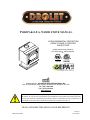
PYROPAK E.P.A. WOOD STOVE MANUAL US ENVIRONMENTAL PROTECTION AGENCY PHASE II CERTIFIED WOOD STOVE Verified and/or tested following ULC S627 and UL 1482 Standards by: Manufactured by: STOVE BUILDER INTERNATIONAL INC. 250, de Copenhague, Saint-Augustin-de-Desmaures (Québec) G3A 2H3 Tel: ( 418 ) 878-3040 Fax: ( 418 ) 878-3001 www.drolet.ca This manual is available for free download on the manufacturer’s web site. It is a copyrighted document. Re-sale is strictly prohibited. The manufacturer may update this manual from time to time and cannot be responsible for problems, injuries, or damages arising out of the use of information contained in any manual obtained from unauthorized sources. READ AND KEEP THIS MANUAL FOR REFERENCE Printed in Canada 45397A 27-03-2012 INTRODUCTION Stove Builder International, one of the most important wood stove and fireplace manufacturers in North America, congratulates you on your purchase and wishes to help you get maximum satisfaction from your wood stove. In the pages that follow, we will give you advice on wood heating and controlled combustion as well as technical specifications regarding installation, operation and maintenance of the model you have chosen. The instructions pertaining to the installation of your wood stove in North America comply with ULC-S627 and UL-1482 standards. We recommend that our woodburning hearth products be installed and serviced by professionals who are certified in the United States by NFI (National Fireplace Institute®) or in Canada by WETT (Wood Energy Technical Training) or in Quebec by APC (Association des Professionnels du Chauffage). Read this entire manual before you install and use your new stove. If this stove is not properly installed, a house fire may result. To reduce the risk of fire, follow the installation instructions. Failure to follow instructions may result in property damage, bodily injury, or even death. Consult your municipal building department or fire officials about restrictions and installation requirements in your area and the need to obtain a permit. KEEP THIS INSTRUCTIONS MANUAL FOR FUTURE REFERENCE. CAUTIONS: HOT WHILE IN OPERATION. CAUSE SKIN BURNS. KEEP CHILDREN, CLOTHING AND FURNITURE AWAY. CONTACT MAY DO NOT USE CHEMICALS OR FLUIDS TO IGNITE THE FIRE. DO NOT LEAVE THE STOVE UNATTENDED WHEN THE DOOR IS SLIGHTLY OPENED DURING IGNITION. DO NOT BURN WASTE, FLAMMABLE FLUID SUCH AS GASOLINE, NAPHTHA, OR MOTOR OIL. DO NOT CONNECT TO ANY AIR DISTRIBUTION DUCT OR SYSTEM. ALWAYS CLOSE THE DOOR AFTER IGNITION. DO NOT INSTALL IN A MOBILE HOME REGISTER YOU WARRANTY ONLINE To receive full warranty coverage, you will need to show evidence of the date you purchased your stove. Keep your sales invoice. We also recommend that you register your warranty online at http://www.drolet.ca/en/service-support/warranty-registration Registering your warranty online will help us track rapidly the information we need on your stove. 2 TABLE OF CONTENTS SECTION 1.0 - INSTALLATION ......................................................................... 4 1.1 GENERAL INSTALLATION................................................................................................. 4 1.2 POSITIONING THE STOVE ................................................................................................. 4 1.3 CLEARANCES TO COMBUSTIBLES AND FLOOR PROTECTOR ............................. 5 SECTION 2.0 CHIMNEY (FLUE SYSTEM) ................................................... 11 2.1 DEFINITIONS ....................................................................................................................... 11 2.2 CHIMNEY .............................................................................................................................. 11 2.2.1 Step by step installation of your factory-built chimney ................................................ 13 2.2.2 Typical installation through an existing masonry chimney .......................................... 22 2.3 CHIMNEY CONNECTOR ................................................................................................... 25 2.4 DRAFT .................................................................................................................................... 27 2.4 DRAFT .................................................................................................................................... 27 2.5 OUTSIDE COMBUSTION AIR ........................................................................................... 27 2.6 THE ADVANTAGE OF INSTALLING A BLOWER (FAN) ........................................... 28 SECTION 3.0 OPERATION ................................................................................ 29 3.1 SAFETY INFORMATION ................................................................................................... 30 3.2 FUEL ....................................................................................................................................... 31 3.2.1 The use of manufactured logs ....................................................................................... 32 3.2.2 Simple wood moisture test ............................................................................................ 33 3.3 NOTES ABOUT FIRST FIRING ......................................................................................... 33 3.4 LIGHTING A FIRE ............................................................................................................... 33 3.5 MAINTAINING THE FIRE ................................................................................................. 34 3.6 BLOWER OPERATION ....................................................................................................... 35 SECTION 4.0 MAINTENANCE ......................................................................... 36 4.1 CLEANING AND PAINTING YOUR STOVE .................................................................. 36 4.2 GLASS ..................................................................................................................................... 36 4.3 GASKETING .......................................................................................................................... 37 4.4 ASH REMOVAL .................................................................................................................... 37 4.5 CHIMNEY (FLUE) CLEANING ......................................................................................... 37 SECTION 5.0 FEATURES................................................................................... 38 5.1 Pyropak ................................................................................................................................... 38 DROLET LIMITED LIFETIME WARRANTY ............................................... 40 3 SECTION 1.0 - INSTALLATION When installed and operated as described in these instructions, the E.P.A Drolet Pyropak wood stove is suitable for use as a freestanding wood stove in residential installations. The E.P.A Drolet Pyropak wood stove is not intended for installation in a bedroom or a mobile home. In Canada, the CSA B365 Installation Code for Solid Fuel Burning Appliances and Equipment and the CSA C22.1 Canadian National Electrical Code are to be followed in the absence of local code requirements. In the USA, the ANSI NFPA 70 National Electrical Code and NFPA 211 Standard for Chimneys, Fireplaces, Vents and Solid Fuel-Burning Appliances are to be followed in the absence of local code requirements. In addition to the national installation and/or local building codes, fire officials (or other authorities having jurisdiction) should be contacted to determine what restrictions and installation requirements might apply locally. 1.1 GENERAL INSTALLATION CAUTION: THE INFORMATION GIVEN ON THE CERTIFICATION LABEL AFFIXED TO THE APPLIANCE ALWAYS OVERRIDES THE INFORMATION PUBLISHED, IN ANY OTHER MEDIA (OWNER’S MANUAL, CATALOGUES, FLYERS, MAGAZINES AND/OR WEB SITES). MIXING OF APPLIANCE OR FLUE SYSTEM COMPONENTS FROM DIFFERENT SOURCES OR MODIFYING THE DIMENSIONAL SPECIFICATION OF COMPONENTS MAY RESULT IN HAZARDOUS CONDITIONS. WHERE SUCH ACTION IS CONSIDERED, THE MANUFACTURER SHOULD BE CONSULTED IN THE FIRST INSTANCE. DO NOT CONNECT THIS UNIT TO ANY AIR DISTRIBUTION SYSTEM. CRACKED AND BROKEN COMPONENTS, e.g. GLASS PANELS OR CERAMIC TILES, MAY RENDER THIS INSTALLATION UNSAFE. A SOURCE OF FRESH AIR INTO THE ROOM OR SPACE HEATED SHALL BE PROVIDED WHEN REQUIRED. CONNECT THE STOVE ONLY TO A LINED MASONRY CHIMNEY CONFORMING TO NATIONAL AND LOCAL BUILDING CODES FOR USE WITH SOLID FUEL, OR TO A LISTED FACTORY BUILT CHIMNEY SUITABLE FOR USE WITH SOLID FUEL. 1.2 POSITIONING THE STOVE It is very important to position the wood stove in an area that will favour the most efficient heat distribution throughout the house. The stove should therefore be installed in the room where the most time is spent, and in the most spacious room possible. Recall that wood stoves produce radiating heat, the heat we feel when we are close to a wood stove. A wood stove also functions by convection, that is through the displacement of hot air accelerated upwards and its replacement with cooler air at the floor level. The stove’s convection effect is facilitated by the installation of a blower. 4 1.3 CLEARANCES TO COMBUSTIBLES AND FLOOR PROTECTOR To install your appliance correctly, it is extremely important to respect all clearances to any combustibles as indicated on your stove’s certification label. Clearances to combustible materials (see figure 1.3 to match each letter to a clearance) CLEARANCES (SINGLE WALL PIPE) A B C D E F K L CANADA 16" (406 mm) 18" (457 mm) 10" (254 mm) 18" (457 mm) 26" (660 mm) 18" (457 mm) 48" (1220 mm) 84" (213 cm) USA 16" (406 mm) 18" (457 mm) 7" (178 mm) 18" (457 mm) 26" (660 mm) 15" (381 mm) 48" (1220 mm) 84" (213 cm) CLEARANCES (DOUBLE WALL PIPE) A B C D E F K L CANADA 16" (406 mm) 18" (457 mm) 7" (178 mm) 18" (457 mm) 26" (660 mm) 15" (381 mm) 48" (1220 mm) 84" (213 cm) USA 16" (406 mm) 18" (457 mm) 7" (178 mm) 18" (457 mm) 26" (660 mm) 15" (381 mm) 48" (1220 mm) 84" (213 cm) 5 FIGURE 1.3 Clearances to combustible materials and floor protection 6 Floor protector If the stove is to be installed on top of a combustible floor, it must be guarded by a non combustible material as shown on figure 1.3 (see the dotted line area). FLOOR PROTECTOR* G H I J M N CANADA 8" (203 mm) – Note 1 8’’ (203 mm) 18" (457 mm) From door opening N/A (USA only) 8" (203 mm) N/A (USA only) USA N/A (Canada only) N/A (Canada only) 16" (406 mm) From door opening 8" (203 mm) N/A (Canada only) Note 2 *Steel with a minimum thickness of 0.015’’ (0.38 mm) or ceramic tiles sealed together with grout. No protection is required if the unit is installed on a non-combustible floor (ex: concrete). Note 1: The floor protection at the back of the stove is limited to the stove’s required clearance if such clearance is smaller than 8 inches (203 mm). Note 2: Only required under the horizontal section of the connector. Must exceed each side of the connector by at least 2 inches (51 mm). Reduced clearances using shielding You may decrease the clearances by installing heat radiation shields between the walls or the ceiling and the stove. These heat radiation shields must be installed permanently, and can include sheet metal, a rigid non-combustible sheet or a masonry wall. Clearances of not less than 1" (25 mm) and not more than 3" (76 mm) between the bottom of the shield and the floor and not less than 3" (76 mm) between the top of the shield and the ceiling must be respected to allow vertical air circulation behind the shield. The shield must extend 20" (500 mm) above the stove top and 18" (450mm) to each side of the stove (see graphic 1). Following the installation of such a heat radiation shield, the clearances mentioned on the stove certification plate may be reduced as stated in the following table. 7 TYPE OF PROTECTION Reducing Clearances With Shielding Sides and Rear/Back Top Sheet metal, a minimum of 0,024" (0,61mm) spaced out at least 1" (25mm) by non-combustible spacers (see graphic 2). 67% 50% Ceramic tiles, or an equivalent non-combustible material on fire-proof supports spaced out at least 1" (25 mm) by noncombustible spacers (see graphic 3). 50% 33% Ceramic tiles, or an equivalent non-combustible material on fire-proof supports with a minimum of 0,024" (0,61 mm) sheet metal backing spaced out at least 1" (25 mm) by noncombustible spacers (see graphic 4) 67% 50% Brick spaced out at least 1" (25 mm) by non-combustible spacers (see graphic 5) 50% N/A Brick with a minimum of 0,024" (0,61 mm) sheet metal backing spaced out at least 1" (25 mm) by non-combustible spacers (see graphic 6). 67% N/A 8 Graphic 1 A- Minimum clearance required between the appliance and an unshielded combustible ceiling. B- 20 in. (500 mm) minimum; C- 1 in. (25 mm) minimum; D- Between 1 in. and 3 in. (25 mm and 75 mm); E- 3 in.(75 mm) minimum; F- 18 in. (457 mm) minimum. 1- Shielding; 2- Non-combustible spacers; 3- Ceiling protector; 4- Combustible wall; 5- Ceiling; 6- Appliance (side view); 7- Appliance (top view). Graphic 2 A- 1 in.(25 mm) minimum; 1- Combustible wall; 2- Non-combustible spacers; 3- 0.024’’ (0.61mm) sheet metal. Graphic 3 A- 1 in. (25 mm) minimum; 1- Combustible wall; 2- Non-combustible spacers; 3- Non-combustible support; 4- Ceramic tile or non-combustible material. 9 Graphic 4 A- 1 in. (25 mm) minimum; 1- Combustible wall; 2- Non-combustible spacer; 3- 0.024’’ (0.61 mm) thick sheet metal; 4- Non-combustible support; 5- Ceramic tile or non-combustible material. Graphic 5 A- 1 in. (25 mm) minimum; 1- Combustible wall; 2- Non-combustible spacers; 3- Brick. Graphique 6 A- 1 in. (25 mm) minimum; 1- Combustible wall; 2- Non-combustible spacers; 3- 0.024’’ (0.61 mm) thick sheet metal; 4- Brick. WARNING: do not install in a sleeping room. 10 SECTION 2.0 CHIMNEY (FLUE SYSTEM) 2.1 DEFINITIONS For clarity, the following definitions should be used with respect to these instructions: A chimney system consists of a connector off the top of the stove, and a chimney, which attaches to the connector and terminates outside the house. A chimney can be a masonry chimney (of masonry construction with an inside liner), or a factory built chimney. A factory built chimney can be a double wall chimney (two concentric pipes with insulation - sometimes referred to as an insulated solid pack) or an air cooled chimney (three concentric pipes, with insulation between the first and second pipes, and air between the second and third pipes). A single wall connector is a single pipe. A double wall connector has two concentric pipes, no insulation, and is an air cooled connector. 2.2 CHIMNEY CAUTION: DO NOT fill any framed space around the factory-built chimney with insulation or any other material. Insulation placed in this area could cause adjacent combustibles to overheat. Do not use makeshift compromises during installation as they may be safety hazards, and a fire could result. Do not connect this unit to a chimney system serving another appliance. Do not cut rafters or ceiling joists without first consulting a building official to ensure structural integrity is not compromised. Your wood stove may be hooked up with a factory built or masonry chimney. If you are using a factory built chimney, it must comply with UL103 (USA) or ULCS629 (Canada) standards. It must therefore be a 6” (152mm) HT Type (2100°F) chimney. It is extremely important that it be installed according to the manufacturer's specifications. The manufacturers’ installation instructions and specified clearances should always be followed in accordance with local and national installation 11 codes. In Canada the CSA B365 and the CSA C22.1 installation codes are to be followed. In the USA the ANSI NFPA 70 and ANSI NFPA 211 installation codes are to be followed. If you are using a masonry chimney, it is important that it be built in compliance with the specifications of the Building Code. It must be lined with fire clay bricks, or clay tiles, sealed together with fire cement, or have a listed solid fuel burning stainless steel liner. Round chimneys are the most efficient. The interior diameter of the chimney should be identical to the stove's smoke exhaust. A chimney which is too small may cause draft problems, since it may not have the required volume to properly evacuate the quantity of smoke resulting from the combustion. A chimney whish is too large may also cause draft problems. In fact, a large chimney will be harder to warm-up and may not reach high enough temperatures to create a proper draft effect. Note that it is the chimney which creates the draft effect, not your stove. Your stove's performance is therefore directly dependent on an adequate draft from your chimney. The following recommendations may be useful for the installation of your chimney: Do not connect your stove to a chimney serving another appliance. The chimney must rise above the roof at least 3' (0.9 mm) from the uppermost point of contact. See Figure 2.2. The chimney must exceed any part of the building or other obstruction within a 10' (3.04 m) distance by a height of at least 2' (0.6 m). See Figure 2.2. The minimum overall height of the chimney system, measured from the stove top to the exterior termination cap of the chimney should be at least 12' (3.66m). A chimney which is too short may lack the “tunnel effect” required to obtain a proper draft. Installation of an interior chimney is always preferable to an exterior chimney. Chimneys constructed outside of the home on an exterior wall should be avoided if possible, especially in colder climates. The gas which circulates into an interior chimney will cool more slowly, thus reducing the build-up of creosote and the risk of flue fires. All else being equal, cooler chimneys will have less draft than hotter ones. This problem will be amplified if the chimney is excessively long. A chimney which is excessively long may be very hard to warm-up due to its higher volume. A cool chimney may even down draft (reverse flow) due to the difficulty in heating it up to operating temperature while trying to evacuate the stack gases. If an exterior chimney is used, the best results will be obtained by using a connector vertically off the unit to the highest possible point before elbowing off horizontally to the exterior chimney. For efficiency and safety reasons the stove must not be installed with an insulated chimney connected directly to the appliance. Using a fire screen at the extremity of the chimney requires regular inspection in order to insure that it is not obstructed, thus blocking the draft. It should be cleaned when necessary. 12 FIGURE 2.2 Minimum Height of the Chimney 2.2.1 Step by step installation of your factory-built chimney The way to install your chimney may vary from one chimney manufacturer to another. The instructions contained in this manual are based on the recommendations of chimney manufacturers whose products are sold at many North American retailers of wood stoves and related heating accessories. Wall support system If your chimney must rise along an outside wall, you need to connect it to your stove through an adjacent wall. For this type of installation, the following items are normally required : Chimney Suitable lengths of chimney (enough to go up to your roof) An adjustable wall support A wall thimble An adequate number of wall bands (one for every 8 feet of chimney, excluding the roof portion) A stove pipe adapter One insulated tee & plug A roof flashing kit (if necessary) A chimney cap. Roof guys (if required) Stove pipe An adequate number of stove pipe sections. A 90o elbow Typical installation through the wall 13 FIGURE 2.2.1 (A) Typical installation through the wall 14 1- Start by positioning your stove where you would like it to go, taking into account the minimum clearances to combustible material. You will then be able to determine where the chimney will pass through the wall. You will probably have to adjust the stove position slightly to ensure that your chimney will run between the studs. You can use a stud finder to locate the studs. Use a spoke saw or jig saw to cut a hole, remembering that you need to maintain a clearance of 2 inches between the chimney and any combustible materials. For concrete walls, cut a hole slightly larger than the outer diameter of the chimney. 2- Once the opening completed, you need to frame in the area to allow for the installation of a wall thimble. A wall thimble is not required for installations through concrete walls. 3- You must first secure the wall thimble into the exterior wall surface. Then, do the same inside and fasten the trim plate. 15 4- Then, from outside the building, slide a short chimney length (attached to the tee) through the wall thimble. The chimney must extend at least 3 inches into the living space where it attaches to the stove pipe. 5- You can now install the wall support. Simply slide the wall support up to the tee, ensuring that the adapter on the support engages with the female coupler on the bottom of the tee. When the wall support is level and properly positioned, you can use lag bolts to secure it into the wall studs. To complete the installation, install an insulated tee plug below the wall support. 6- You can start to add chimney sections. We recommend that you also use locking bands to secure all connections. You will need to secure the chimney to the house using wall bands. Wall bands wrap around the chimney and then attach to the wall. Install the first one 3 feet above the wall support. Then, you will need another band for each 8 feet of chimney. Note: if your chimney must be installed through your soffit, install a roof flashing above and finishing plate below where the roof is cut. Consult the following section called “CEILING SUPPORT SYSTEM” for more details. 16 7- Authorities require that the chimney extend not less than 3 feet above the highest point where it passes through the roof of a building and not less than 2 feet above any portion of the building within 10 feet. If the chimney extends more than 5 feet above the roof deck, roof guys with telescoping legs and draw bands are required. 8- Finally, twist on your rain cap and you can head back inside. 9- You are now ready to connect your chimney to your stove. Simply install the inter-connecting stove pipe between the stove pipe adapter and the stove. You can follow the instructions in the following section (section 2.3) of this manual called « CHIMNEY CONNECTOR». 17 Ceiling support system If your chimney must rise inside the house and go through the ceiling, you need to connect it to your stove at the ceiling level. For this type of installation, the following items are normally required : Chimney An adequate number of chimney sections (enough to go up to your roof) A ceiling support kit with stove pipe adapter An attic insulation shield A roof flashing kit A chimney cap Roof guys (if necessary) Stove pipe Suitable lengths of stove pipe Typical installation through the ceiling 18 FIGURE 2.2.1 (B) Typical Installation Through the Ceiling 1. Place your stove where you would like it located and use a plumb line to mark the ceiling directly above your stove flue. You will probably have to adjust this position slightly to ensure that your chimney will run between the joists. You can use a stud finder to locate the joists. You also need to take into account the minimum clearances to combustible materials. After you have determined where the chimney will go through the ceiling, use a spoke saw or power jig saw to cut a hole, remembering that you need a minimum 2-inch clearance between the chimney and any combustible materials. Depending on whether you have a one or two story structure, you will need to cut a matching hole through the floor of the attic or second floor living space. 2. Before you install the ceiling support, you need to frame the area. 3. To install the ceiling support, just slide the assembly into the framed opening from below. Once you ensure that the finishing plate is flush with the underside of the ceiling and assembly is level, secure it with screws. 19 4. Once the support is secure, you can begin to assemble the chimney by lowering the first section into the support. Make sure that the male coupler is pointing upwards, as indicated by the arrow on the chimney label. 5. Then, from beneath the support, insert the stove pipe adapter and twist-lock it into place. 6. Now, you can add additional chimney sections. Continue adding chimney lengths until a height of about 2 feet below the next ceiling level. An attic insulation shield must be installed where a chimney passes from a lower living space into an upper living space or attic space. It is designed to keep insulation materials away from the chimney. A second attic insulation shield must be installed if your chimney passes from a lower living space into an upper living space. As wee, you must enclose all sections of the chimney where is passes through a living space. Elbows (15o or 30o) are used when you need to offset your chimney to clear an obstruction or to avoid having to cut joists. 20 7. Once you have cut through your roof and framed the joists, it is time to work outdoors. Authorities require that the chimney extend not less than 3 feet above the highest point where it passes through the roof of a building and not less that 2 feet above any portion of the building within 10 feet. You will need to install a roof flashing. The roof flashing slides over your chimney pipe and goes under your shingles. Once you have done that, check that everything is plumb, and nail the flashing into the roof deck. Seal the joint between the shingles and the plate with silicone. 8. Next, slide the storm collar down the chimney until it contacts the flashing. Tighten the nut and bolt and seal the collar to the chimney with a waterproof, non-combustible silicone sealant. Finally, twist on your rain cap and you can head back inside. If the chimney extends more than 5 feet above the roof deck, roof guys with telescoping legs and draw bands are required. 9. You are now ready to connect your chimney to your stove. Simply install the inter-connecting stove pipe between the stove pipe adapter and the stove. You can follow the instructions in the following section (section 2.3) of this manual called « CHIMNEY CONNECTOR». 21 2.2.2 Typical installation through an existing masonry chimney You can also install your stove using your existing masonry chimney. To do so, follow the guidelines below. You may want to use a factory-built thimble, on construct your own brick thimble. If you are using a masonry chimney, it is important that it be built in compliance with the specifications of the Building Code in your region. It must normally be lined with fire clay bricks, metal or clay tiles sealed together with fire cement. (Round flues are the most efficient). FIGURE 2.2.2 (A) Typical Installation Through an Existing Masonry Chimney 22 FIGURE 2.2.2 (B) Factory Built Thimble 23 FIGURE 2.2.2 (C) Brick Thimble 24 2.3 CHIMNEY CONNECTOR Your chimney connector (commonly called stove pipe) and chimney must have the same diameter as the stove’s exhaust outlet. The stove pipe must be made of aluminized or cold roll steel with a minimum 24-gauge thickness (0.021" or 0.53 mm). It is strictly forbidden to use galvanized steel. The following recommendations may be useful for the installation of your chimney connector: Your chimney connector should be assembled in such a way that the male end (crimped) faces down to prevent creosote dripping outside the joints. Attach each of the sections to one another with three equidistant metal screws. Also use three equidistant metal screws to attach the connector to the stove’s exhaust collar. See Figure 2.3 (A) and Figure 2.3 (B). The pipe must be short and straight. All sections installed horizontally must slope at least ¼ inch per foot, with the upper end of the section toward the chimney. See Figure 2.3 (B). To insure a good draft, the total horizontal length of the connector should never exceed 8' to 10' (2.4 to 3.04 m). In the case of vertical installation, the total length of the connector can be much longer and connected without problem to the chimney at the ceiling level. There should never be more than two 90 degrees elbows in the whole connector and chimney system. Never start with a 90o elbow. Always go up vertically for at least 2 feet from the flue spigot before using a 90o elbow. The connector must not pass through any combustible material, nor may it pass through a concealed space (such as an attic, roof space, or closet). If passing through a wall, ceiling, or into a masonry chimney, use either chimney components listed for that specific use, or means acceptable to local authorities having jurisdiction over the installation. Installation of a "barometric draft stabiliser" (fireplace register) on a connector is not recommended. FIGURE 2.3 (A) Connecting Sections 25 FIGURE 2.3 (B) Minimum Slope Avoid 90 degree eblows We recommend that you use two 45 degree elbows instead 26 2.4 DRAFT Your E.P.A Drolet stove’s performance will be optimised if it is installed with a chimney (flue) system that provides an adequate draft. The draft is the force that moves air from the appliance up through the chimney and is predominantly affected by the height and diameter of the chimney, as well as the stack temperatures of the stove. If you test the draft using a pressure gauge, the reading should be between .05 - .07 inches of water column (w.c.) at a medium-high fire. A draft measure of less than .03" w.c. will cause operational difficulties while too much draft (greater than .10" w.c.) will result in over-firing of the stove. This can result in excessive operating temperatures. In this case, the installation of elbows totaliing no more than 180° (ex.: 2 x 30° elbows, 2 x 45° elbows or 2 x 90° elbows) can be installed to help reduce excessive draft. If the addition of elbows is not sufficient, a manual damper can be installed in the vertical flue pipe. 2.5 OUTSIDE COMBUSTION AIR It is recommended to install 3’’ (76mm) outside air intake in the room where the stove is located or nearby. The following are signs that a fresh air kit may be required: Your stove does not draw steadily, smoke rollouts occur, wood burns poorly, or back-draft occurs whether or not there is combustion present. Existing fuel-fired equipment in the house, such as fireplaces or other heating appliances, smell, do not operate properly, suffer smoke rollouts when opened, or back-draft occurs whether or not there is combustion present. Opening a window slightly on a calm (windless) day alleviates any of the above symptoms. The house is equipped with a well-sealed vapour barrier and tight fitting windows and/or has any powered devices that exhaust house air. There is excessive condensation on windows in the winter. A ventilation system is installed in the house. 27 2.6 THE ADVANTAGE OF INSTALLING A BLOWER (FAN) A blower can be installed at the back of your E.P.A Drolet Pyropak stove. This option is necessary if you wish to redistribute into a room the heat trapped at the back of your stove. By forcing hot air toward the front, the blower enables you to extend the radiation and convection power of your stove. You can purchase this option through your E.P.A Drolet dealer. Make sure you specify the correct part number: AC02050. Installation instructions are supplied with the blower. 28 SECTION 3.0 OPERATION Keep these instructions for future reference. WARNING: ANY MODIFICATION OF THE APPLIANCE THAT HAS NOT BEEN APPROVED IN WRITING BY THE TESTING AUTHORITY IS CONSIDERED AS BREACHING CSA B365 (CANADA), AND ANSI NFPA 211 (USA). NEVER MODIFY THE AIR INTAKE CONTROL. DO NOT USE FLAMMABLE LIQUIDS OR AEROSOLS TO START OR REKINDLE THE FIRE. DO NOT USE FLAMMABLE LIQUIDS OR AEROSOLS IN THE VICINITY OF THIS APPLIANCE WHEN IT IS OPERATING. DO NOT STORE FUEL WITHIN HEATER INSTALLATION CLEARANCES. OPEN AIR CONTROL (AND DAMPER WHEN FITTED) BEFORE OPENING FIRING DOOR. THIS STOVE IS NOT DESIGNED TO BE USED WITH THE DOOR OPEN. THE DOOR MAY BE OPEN ONLY DURING LIGHTING PROCEDURES. NEVER LEAVE THE STOVE UNATTENDED WHEN THE DOOR IS OPEN. HOT WHILE IN OPERATION, KEEP CHILDREN, CLOTHING AND FURNITURE AWAY. CONTACT MAY CAUSE SKIN BURNS. WEAR GLOVES TO OPERATE YOUR STOVE. CAUTION THIS APPLIANCE SHOULD BE MAINTAINED AND OPERATED AT ALL TIMES IN ACCORDANCE WITH THESE INSTRUCTIONS. THE USE OF SOME TYPES OF PRESERVATIVE-TREATED WOOD AS A FUEL CAN BE HAZARDOUS. 29 3.1 SAFETY INFORMATION These stoves are designed for safe operation WHEN BURNING WOOD ONLY. Altering or modifying the unit or installation without proper authorisation will void the certification, warranty, and safety listing, and may result in a safety hazard. For safety reasons, never leave the unit unattended with the door open or ajar. An open door, and especially a door partially open or cracked, if left for longer than required for good ignition can potentially result in unsafe chimney temperatures, and if left unattended, in hot embers or ignited fuel falling out of the unit. Prolonged door open operation is not necessary provided the unit has been properly installed and dry kindling is used to start the fire. Do not abuse the unit, either by over firing or by using wood or combustibles with salt content, or harmful chemicals. Misuse is not covered by warranty. Even though your E.P.A Drolet has been specifically designed and tested to prevent smoke spillage, always open the door slowly as this will minimise the likelihood of smoke spillage or a back draft of flame or smoke into the room. Never use gasoline type lantern fuel, kerosene, solvents, charcoal lighter fluid, or inflammable liquids to start or "refresh" a fire in the stove. Keep all such liquids well away from the stove while it is in use. All stove surfaces become very hot during operation. Care is needed, especially with children, to avoid contact with those surfaces. Do not elevate the fire by means of grates. CAUTION: DO NOT OVER FIRE THIS HEATER. Do not burn fuel in the stove at a rate higher than that which will cause the ember bed level to exceed half the door opening height. We strongly recommend that you purchase a chimney (flue) thermometer. There are two types of thermometers: probe thermometers and magnetic thermometers (the later is also called “stove top thermometer”). If you are using a probe thermometer, make sure that the temperature does not exceed 900oF (482oC). If you are using a magnetic thermometer, make sure that the temperature does not exceed 475oF (246oC). If the door handle of the stove becomes excessively hot to the touch, consider this to be an indication of over firing. Over firing can result in a safety hazard and can permanently damage the stove and chimney. This damage is not covered by the warranty. 30 Although the ceramic glass is extremely durable under any normal use, a few precautions are required. Do not attempt to push logs further into the fire by using the door, as the glass may break if any solid object heavily contacts it. Never operate the stove with the door open, or cracked slightly open, except briefly during the lighting operation, and during refuelling. Leaving the door open continuously could seriously overheat the chimney and adjacent combustibles. Do not operate the stove if there is an abnormal air leakage into the stove, such as through deteriorated gaskets or cracked or broken glass. Do not operate the stove without a door gasket. Leakage can result in overheating, or in very airtight homes, could possibly cause smoking into the room. Smoke may contain carbon monoxide, which is poisonous, and in sufficient quantities, is a health hazard. 3.2 FUEL Fuel for the stove must not be stored closer than the required clearances to combustibles (heat sensitive materials). NEVER STORE WOOD IN THE ASH PAN COMPARTMENT. Your E.P.A Drolet stove is designed to burn WOOD ONLY. Do not burn coal, charcoal, or trash in the unit. Highly flammable items such as trash may ignite creosote in the chimney (flue), resulting in a chimney fire. Never burn salt wood, beach wood, chemically treated wood, or wood removed from salt water, since the deposits left will deteriorate the firebox. Damage caused by chemicals or salt is not covered under warranty. Seasoned cord wood is recommended. Wood should be air dried in a covered and ventilated area for a minimum of six months (one year or more is recommended). This reduces the moisture content of the wood, resulting in a better stove performance. Wood species with moisture content of 20% or less are ideal. Dry, seasoned cord wood, can be distinguished from green wood by the cracks at each end of the logs. Wet or green wood will tend to cause the fire to smoulder, producing large amounts of creosote. Creosote buildup could result in a chimney fire. This wood will also prove difficult to keep burning properly, and fires will tend to go out. Green wood produces very little heat, and sometimes causes customers to think that the stove does not work. Decayed wood or low-density wood has very little energy content or heating value, and will not burn satisfactorily for long periods of time. An example of the energy values of some common wood fuels found un North America is given in the following table: 31 Energy yield (millions of BTU/cord) Oak 29 Sugar Maple 28 Beech 26 High energy yield Yellow birch 25 Ash 24 Elm 23 Larch (Tamarack) 23 Red Maple 23 Douglas red fir 23 Medium energy yield Silver birch 22 Alder 18 Poplar 17 Hemlock 17 Spruce 17 Pine 17 Low energy yield Bass 16 Fir 13 Data provided by Energy, Mines and Resources – Canada Wood species TABLE 3.2 Energy yield for wood species 3.2.1 The use of manufactured logs There are numerous types of manufactured logs sold on the market. You must be very careful with this type of product. Many brands of manufactured logs contain chemical additives. DO NOT BURN ANY MANUFACTURED LOGS CONTAINING CHEMICAL ADDITIVES. If you do, you may damage your stove and void the warranty. Logs containing chemical additives burn a lot hotter and were designed for decorative fireplaces. Decorative fireplaces generally have larger, cooler, and less air-tight fireboxes. Your E.P.A Drolet stove, on the other hand, has a smaller, completely sealed firebox which attains much higher temperatures. It is therefore not designed to support excessive heat caused by the addition of chemicals in manufactured logs. Manufactured logs made of 100% wood residues do not cause any threat to your stove. You must however be careful. Manufactured logs typically release a much larger heat output over a short period of time. Therefore, you cannot place a large quantity of such logs into your stove, like you would with regular cord wood. Start with one log, and gradually increase the load to 2 or 3 logs and see how your stove reacts. Use a chimney (flue) thermometer and make sure that temperatures remain within the normal operating range. 32 3.2.2 Simple wood moisture test Add one large piece of wood to the top of an established fire. If it starts to burn on three sides within one minute, it is dry and seasoned and right for burning. If it turns black and starts to burn in about three minutes or more, it is damp. If it turns black and does not start burning until five minutes or more, it is green and wet. If it hisses at any time, the wood is soaked and will not burn until the excess of moisture is boiled away. 3.3 NOTES ABOUT FIRST FIRING The fresh paint on your stove needs to be cured to preserve its quality. Once the fuel load is properly ignited, only burn small fires in your stove for the first four hours of operation. Never open the air control more than necessary to achieve a medium burn rate. Make sure that there is enough air circulation while curing the stove. Open one or more windows. The odours can be smelled during the 3 or 4 first fires. Never start your stove outside. 3.4 LIGHTING A FIRE Place enough crumpled balls of newspaper or other paper into the stove to cover thbottom of the firebox. Place small and dry kindling on the crumpled paper. Place larger and dry kindling on top of the small kindling. Open the air intake control fully. Light a fire at the bottom of the crumpled paper and close the door. If the fire tends to go out momentarily, hold the door slightly ajar to activate the fire. As soon as the fire catches hold, close the door. Ideally the large kindling should be burned until a thick bed of red embers is obtained. At that point, add cord wood fuel and continue to operate the draft control wide open until the fire is well established. Once the firebox is hot, the air control can be partially closed. After 30 minutes to one hour, you can close the air control completely. In order to have the best indication of when you should close the air control completely to operate your stove the most efficiently, use a chimney (flue) thermometer. If you are using a probe thermometer, you can close the air control completely when the temperature on the thermometer reaches 900oF (482oC). If you are using a magnetic thermometer, you can close the air control completely when the temperature on the thermometer reaches 475oF (246oC). Closing the air control 33 down too soon will lower combustion efficiency and may cause the fire to die out. Over a period of time, it may also result in creosote build-up in the chimney (which could lead a chimney fire). CLOSED OPEN 3.5 MAINTAINING THE FIRE Once the wood has been consumed (or partially consumed) and you have obtained a good bed of embers, you should reload the unit. In order to do so, open the air control to its maximum for approximately 15 seconds prior to opening the stove door. Then, proceed by opening the door very slowly. Open it by 2” to 4” (52 to 104 mm) for 10 to 15 seconds before opening it completely. This procedure will increase the draft and thus eliminate the smoke which is stagnant in a state of slow combustion in the stove. Then, bring the red embers to the front of the stove and reload the unit. Depending on the type of wood you burn and the strength of the draft in your flue, you may have to leave the air control open to its maximum for more than 15 seconds to avoid smoke spillage before you reload the stove. Your E.P.A Drolet stove will work best if a thick bed of hot embers is maintained in the bottom of the firebox, and a minimum of two large pieces of seasoned fuel are added. Combustion efficiency is largely related to establishing a hot ember bed, and hot firebox temperatures. The quicker the stove and chimney (flue) get up to normal operating temperatures, the better. A small intense fire is preferred to a large smouldering fire, both to improve combustion efficiency and to reduce the amount of creosote build-up. The best performance will be obtained by adding relatively small amounts of fuel to a well established ember bed, and then operating with the air inlet control open long enough to achieve a hot fire. The wood should be placed with air in between individual pieces. Use a poker to make an air channel in the embers below the wood. This will allow air to flow under the wood for a more efficient burn. 34 In order to achieve an optimum efficiency from your unit, we suggest that you operate it with the air control completely closed. Make sure that you have a good fire going and an adequate ember bed before you completely close the air control. Use a chimney thermometer if necessary. Closing the air control too soon will lower combustion efficiency and may cause the fire to die out. The addition of a blower (if not already included) is highly recommended to maximize your unit’s efficiency. 3.6 BLOWER OPERATION If your stove has a fan or if you have install an optional blower, allow the stove time to reach its operating temperature (approximately one hour), before starting the blower. The air blown by the blower cools down the stove and affects the efficiency of the combustion when the blower is turned on too quickly. WARNING: TO PREVENT ELECTRIC SHOCK, MAKE SURE THE POWER CORD BLOWER IS NOT IN CONTACT WITH ANY STOVE SURFACE. DO NOT ALLOW THE CORD UNDER THE STOVE. 35 SECTION 4.0 MAINTENANCE 4.1 CLEANING AND PAINTING YOUR STOVE Clean the stove frequently so that soot, ash, and creosote do not accumulate. Do not attempt to clean the stove when the unit is hot. Special care must be taken with gold plated surfaces in order to maintain the finish at its original brilliance. Do not use an abrasive cleaner which will scratch the paint or plated finish. Use only a soft and clean damp cloth. If the paint becomes scratched or damaged, it is possible to give your wood stove a brand new look, by repainting it with a 650oC heat resistant paint. For this purpose, simply scrub the surface to be repainted with fine sand paper, clean it properly, and apply thin coats (2) of paint successively. To retrieve the original finish, use the paint supplied by the manufacturer. 4.2 GLASS Inspect the glass regularly in order to detect any cracks. If you spot one, turn the stove off immediately. Do not use the stove if the glass is broken. Do not close the glass door by sticking or slamming shot. Do not use the stove if the glass is broken. If the glass on your stove breaks, replace only with a ROBAX® glass 5mm thick supplied by your E.P.A Drolet dealer. Never use a substitute material. To replace the glass, remove the screws retaining the glass retainers inside the door. Remove the mouldings and replace the damaged piece with a new one. Perform the procedure backwards after replacing. When replacing the glass, you should change the glass gasket to make sure you keep it sealed. Never wash the glass with a product that may scratch it. Use a specialized product, available in the stores where wood stoves are sold. Only wash when the stove is cold. Under normal operating conditions, the glass is designed to stay clean. Glass cleaning may be required when burning damp wood. Furthermore, small creosote or soot accumulation may occur in the lower end corners of the glass when burning the stove with the air control at the minimum setting. This is normal. The glass will clean itself when burning a hot fire during one hour or more with the air control at its maximum setting. Nevertheless, cleaning the glass on a regular basis is recommended to prevent thicker creosote or soot accumulation that can be very hard to remove. 36 4.3 GASKETING It is recommended that you change the door gasket (which makes your stove door air tight) once a year, in order to insure good control over the combustion, maximum efficiency and security. To change the door gasket, simply remove the damaged one. Carefully clean the gasket groove, apply a high temperature silicone sold for this purpose, and install the new gasket. Use only the genuine Drolet gasket. You may light up your stove again approximately 24 hours after having completed this operation. 4.4 ASH REMOVAL CAUTION: ASHES CAN START FIRES, EVEN AFTER SEVERAL DAYS OF INACTIVITY. NEVER DISPOSE OF ASHES IN A COMBUSTIBLE CONTAINER. REMOVE ASHES WHEN THE STOVE AND ASHES ARE COLD. Ashes should be removed from the stove every few days or when ashes get to 2 to 3 inches deep. Always empty the stove when it is cold, such as in the morning. 23 24 Always dispose of ashes in a metal container with a tight fitting lid. Place this container on a non combustible floor or on the ground, well away from all combustible materials, pending final disposal. If the ashes are disposed of by burial in soil or otherwise locally dispersed, they should be retained in the close container until all cinders have thoroughly cooled. 4.5 CHIMNEY (FLUE) CLEANING Regular chimney (flue) maintenance, as well as good burning practices, are required to prevent chimney fires. When wood (especially green wood) is burned without adequate heat or air supply, it produces tar and other organic vapours (smoke), which combine with expelled moisture to form creosote. The creosote vapours condense in the relatively cool chimney of a slow-burning fire. As a result, creosote residues accumulate on the chimney. When ignited, this creosote makes an extremely hot fire which could be hazardous. Your E.P.A Drolet stove has been designed to reduce the amount of creosote produced. Even so, the chimney and any chimney connector should be inspected at least once every two months during the heating season to determine if a creosote build-up has occurred. If creosote has accumulated, it should be removed to reduce the risk of a chimney fire. Call a professional chimney sweep, or go to your local E.P.A Drolet dealer, purchase a chimney brush, and have the chimney cleaned. The chimney and chimney connector must be in good condition and kept clean. Contact your local, municipal, state, or provincial fire authority for information on how to handle a chimney fire before there is any chance that it may happen. 37 SECTION 5.0 FEATURES 5.1 Pyropak Type of fuel Wood Test standard ULC S627 (CSA B366.2) and UL 1482 for residential. Recommended surface: 500 to 1000 sq. ft. Heating capacity* – BTU/hr., EPA test wood: 26,100 Heating capacity* – BTU/hr., seasoned cordwood: 40,000 Optimum efficiency: 82% *Why is the BTU indicated on the EPA label smaller than the one advertised? You will notice a difference between the BTU output as indicated on the unit’s white EPA label affixed to the glass and the BTU as advertised on our web site and/or product literature. The maximum BTU output we advertise for this unit is what will be obtained with a full load of seasoned cordwood inserted inside the firebox. The EPA output, on the other hand, is what has been obtained during emissions testing. The EPA test procedure requires that a special type of wood be used and positioned inside the firebox in a manner that does not represent the way the firebox volume would normally be utilized using seasoned cordwood. The EPA test load is typically much smaller. Hence, the BTU as per the EPA label is reduced. The BTU output that should be considered by a normal user is the one we advertise for seasoned cordwood. Shipping Weight 220 lbs. (99.8 kg) Firebox Volume : 1.3 cubic feet (0,037 m3) Firebox Floor Area: 18’’W x 12.5’’D (457 mm x 317 mm) Door Opening Size 15’’W x 7.75’’H (381 mm x 196.8 mm) Maximum Log Size 17’’ (431 mm) Flue Outlet 6’’ diameter (152 mm) - vertical 38 BRICK LAYOUT ITEM 1 2 3 4 PART # 29010 PL36055 29015 PL36027 DESCRIPTION 4 ½” X 9” BRICK 4 1/2'” X 9” BRICK (CUT) 4” X 9” BRICK 3" X 9" X 1 1/4'' BRICK QTY 12 2 2 2 39 DROLET LIMITED LIFETIME WARRANTY The warranty of the manufacturer extends only to the original consumer purchaser and is not transferable. This warranty covers brand new products only, which have not been altered, modified nor repaired since shipment from factory. Proof of purchase (dated bill of sale), model name and serial number must be supplied when making any warranty claim to your DROLET dealer. This warranty applies to normal residential use only. Damages caused by misuse, abuse, improper installation, lack of maintenance, over firing, negligence or accident during transportation, power failures, downdrafts, or venting problems are not covered by this warranty. This warranty does not cover any scratch, corrosion, distortion, or discoloration. Any defect or damage caused by the use of unauthorized parts or others than original parts void this warranty. An authorized qualified technician must perform the installation in accordance with the instructions supplied with this product and all local and national building codes. Any service call related to an improper installation is not covered by this warranty. The manufacturer may require that defective products be returned or that digital pictures be provided to support the claim. Returned products are to be shipped prepaid to the manufacturer for investigation. If a product is found to be defective, the manufacturer will repair or replace such defect. Transportation fees to ship the product back to the purchaser will be paid by the manufacturer. Repair work covered by the warranty, executed at the purchaser’s domicile by an authorized qualified technician requires the prior approval of the manufacturer. Labour cost and repair work to the account of the manufacturer are based on predetermined rate schedule and must not exceed the wholesale price of the replacement part. All parts and labour costs covered by this warranty are limited according to the table below. The manufacturer at its discretion may decide to repair or replace any part or unit after inspection and investigation of the defect. The manufacturer may, at its discretion, fully discharge all obligations with respect to this warranty by refunding the wholesale price of any warranted but defective parts. The manufacturer shall in no event be responsible for any special, indirect, consequential damages of any nature, which are in excess of the original purchase price of the product. A one-time replacement limit applies to all parts benefiting from a lifetime coverage. This warranty applies to products purchased after October 1st, 2011. DESCRIPTION Combustion chamber (welds only) and castings. Stainless steel firebox components, secondary air tubes*, surrounds and heat shields, ash drawer, steel legs, pedestal, trims (aluminum extrusions), plating* (defective manufacture), and convector air-mate. Carbon steel firebox components, glass retainers, handle assembly, C-Cast baffle*, and vermiculite baffle*. Standard blowers, heat sensors, switches, rheostat, wiring, and other controls. Optional blowers, ceramic glass (thermal breakage only*), paint (peeling), gaskets, insulation, and ceramic fibre blankets. Firebrick *Pictures required WARRANTY APPLICATION PARTS LABOUR Lifetime 3 years 5 years 3 years 3 years 1 year 2 years 1 year 1 year n/a n/a n/a Shall your unit or a components be defective, contact immediately your DROLET dealer. Prior to your call make sure you have the following information necessary to your warranty claim treatment: Your name, address and telephone number; Bill of sale and dealer’s name; Serial number and model name as indicated on the nameplate fixed to the back of your unit; Nature of the defect and any relevant information. Before shipping your unit or defective component to our plant, you must obtain from your DROLET dealer an Authorization Number. Any merchandise shipped to our plant without authorization will be refused automatically and returned to sender. 40