1
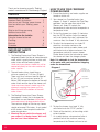
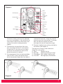
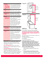
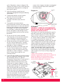
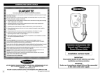
520M/520TS
Manual and Thermostatic
Power Shower Units
Installation instructions & User guide
IMPORTANT: This booklet should be given to the customer after installation and demonstration.
WARNING: Under no circumstances should this unit be connected to the mains water supply.
Thank you for choosing a quality 'Redring'
product manufactured in Peterborough, England.
HOW TO USE YOUR 'REDRING'
POWER SHOWER
CONTENTS
1. Ensure the electricity and water supplies are
turned on to the unit.
2. Your shower has 2 control knobs (see
diagram 1). Knob 'A' controls the Start/Stop
operation and the water flow rate of the
Shower unit. Knob 'B' controls the
temperature of water and also incorporates a
temperature limiter.
3. To start the shower turn knob 'A' clockwise
from the STOP position. Adjust the control
until a satisfactory flow rate is achieved. For
maximum flow, turn Knob 'A' fully clockwise.
4. To adjust the temperature, turn knob 'B'
clockwise to a lower number on the
temperature scale for a cooler shower and
anti-clockwise to a higher number on the
temperature scale for a warmer shower.
Please allow time for the hot water to reach
the shower unit from the storage cylinder.
Note: It is advisable to test the temperature
of the water with your hand before stepping
under the showerhead.
Page
Information for the user
Important Safety Instructions
How to use your 'Redring' power shower
How to maintain your 'Redring' power
shower
What to do if things go wrong
Additional accessories
4
4
10
Information for the installer
Fixing the shower to the wall
Plumbing
Electrical
Guarantee
5
6
9
12
2
2
IMPORTANT SAFETY
INSTRUCTIONS
1. The Redring Expressions Power Shower is
designed to boost the flow of stored domestic
water, which is gravity fed from a static cold
water cistern and hot water cylinder.
Under no circumstances should this unit be
connected directly to the mains cold or hot
water supplies.
2. The cold water cistern should have a
minimum capacity of 114 Litres (25 galls).
There must be a minimum head of water of
8.0 cm (3") and a maximum head of 10
Metres (33ft) between the bottom of the cold
water cistern and the top of the shower unit.
Under no circumstances should any of the
pipework supplying the shower unit rise
above the level of the bottom of the cold
water cistern.
3. The Redring Expressions Power Shower
incorporates a motor that is designed for
intermittent use and therefore should not be
used continuously for long periods of time.
The maximum length of time for any shower
should not exceed 15 minutes. A rest period
of 45 minutes is then required to allow the
motor to cool down.
4. Warning! Do not switch the shower on if
you suspect it of being frozen. Wait until
you are sure it has thawed out.
2
Diagram 1
Knob 'A'
(Start/stop and
flow rate control).
Temperature
overide button.
Control knob
cap.
Knob 'B'
(Temperature
adjust).
5. To stop the shower, turn knob 'A' fully
anti-clockwise to the 'STOP' position.
6. Switch off the electricity at the ceiling switch
or local isolator.
7. As a safety feature, a temperature limiter is
provided so that the maximum working
temperature of the Shower unit can be set.
Top Fixing Holes
Diagram 2
Motor
Terminal
Block
Rating Plate
Position
Cable
Clamp
PCB Enclosure
Commissioning
Link
Pump Assy
Cold Inlet
Port
Hot Inlet
Port
Solenoid
Bottom Fixing
Holes
Side Section
Filter
Housing
Outlet
Mixer
Chamber
The limiter is factory set but can be adjusted
to suit on site conditions. If the position of the
limiter requires adjustment please refer to the
section in the commissioning procedure
(page 9).
8. To override the stop position of the limiter,
press the button on Knob 'B' and continue
turning Knob 'B' anti-clockwise to a higher
number on the temperature scale until the
desired temperature is reached.
9. If the temperature limiter has been overridden,
knob 'B' MUST always be returned to the
normal temperature range when the shower is
switched off. To do this, simply turn knob 'B'
clockwise past the limiter position. The button
does not need to be depressed when
returning to the normal temperature range.
10. There are 4 defined spray settings provided by
the handset (See diagram 3).
The ring can be turned in either direction to
change the spray pattern.
a) Spray:
Powerful fine jets.
b) Massage:
Sparkling pulsating massage.
c) Champagne: Soft, aerated, relaxing spray.
d) Pulse Mix:
Massage/Spray Combination.
a)
c)
b)
d)
Ring
Diagram 3
3
Diagram 4
The spray head rotates
through approximately 140o
c) Water too
cold
Turn Temperature Control Knob
(B) anti-clockwise to a higher
number on the temperature
scale (see diagram 1).
Check that hot water is
available in the hot water
cylinder. The ideal thermostat
setting for the hot water
storage cylinder is 60oC
(140oF).
Check that the HOT water
isolating valve is open.
If possible, reposition
temperature limiting device so
that more movement of Knob
'B' is allowed.
d) Water too
hot
Turn Temperature Control
Knob (B) clockwise to a lower
number on the temperature
scale. Check that the COLD
water isolating valve is open.
e) Poor spray
pattern
Clean showerhead (see
opposite).
IN ORDER TO MAINTAIN THE
PERFORMANCE OF YOUR
SHOWER YOU MUST CLEAN
THE SHOWERHEAD.
NOTE: After use it is normal for some water to
drip from the shower head for a few moments.
HOW TO MAINTAIN YOUR
'REDRING' POWER SHOWER
All water contains particles of lime which build up
in the showerhead and unit reducing the
performance. It is therefore important to clean the
showerhead by dipping it in a suitable descaling
solution. The frequency of this will vary depending
on site water conditions.
Cleaning
WARNING: Switch off the electricity at the
isolating switch to avoid the shower
accidentally switching on during cleaning.
It is recommended that the shower unit and
accessories are cleaned using a soft cloth.
DO NOT use powerful abrasive or solvent
cleaning fluids.
WHAT TO DO IF THINGS GO
WRONG
Self Help
If the performance of the shower does deteriorate
in service make the following checks before
calling out the contractor. Any one of these
simple adjustments could restore the
performance.
4
a) System will
not operate
Check that the mains
electrical supply is switched
on.
b) Pump
operates but
no water is
delivered
Check that water is available
to both ports, and that all
isolating valves are open.
Check for an airlock in the
pump chamber. Repeat
commissioning procedure on
page 9.
Professional Service
If the above checks fail to restore the
performance, you should seek professional help.
The person who installed the shower is probably the
best one to repair it and is certainly the person to
contact if you have a problem in the guarantee
period.
The following additional checklist is provided for the
benefit of the qualified serviceman.
WARNING: SWITCH OFF THE ELECTRICITY AT
THE ISOLATING SWITCH BEFORE REMOVING
THE COVER TO MAKE CHECKS.
a) Pump
operates but
no water is
delivered
Check that the inlet connections
to the mixing chamber are piped
correctly.
Check that the shower and all
pipework are sited below the level
of the cold water tank and that it
is fully primed and is therefore not
airlocked. See commissioning
procedure (page 9).
b) Pump
operates
when motor
is switched
off
Check for faulty potentiometer
switch, (located under knob
'A' inside front cover). Switch
should be open circuit when
turned fully anti-clockwise.
c) Water too
hot
Blockage in filter causing
obstruction in water supply.
Check and clean (see page 10).
d) Water too
cold
Blockage in filter causing
obstruction in water supply.
Check and clean (see page 10).
Check that the hot and cold
e) Poor
temperature water supplies are delivered
adjustment to the correct ports.
Check that water is supplied
to the shower unit at
balanced pressures (ie. Hot
and cold water are supplied
from the same header tank).
Ensure cold supply is not
taken from mains.
f) Unit does
not prime
Check that the shower and all
pipework are sited below the
level of the cold water tank.
g) Poor flow
rate
Are there any restrictions in
the 15mm supply (reduced
diameters even for short
distances).
Is the pressure being lost to
other services in the dwelling.
Check filter for obstructions in
the water supply and clean if
necessary. See page 10 for
details.
REDRING AFTER SALES SERVICE
We offer a technical advisory service on the
telephone to contractors and other customers
with problems in the field.
Ring 0870 9000 430 (Normal Office Hours)
Spare parts can be supplied against any VISA or
Access cards.
Ring 0870 9000 420 (Normal Office Hours)
Remember to quote the exact type of shower, as
written on the front of the shower and on this
leaflet. It may also be of use to have a note of the
Catalogue Number as stated on the rating plate
inside the shower (see diagram 2 for location)
Diagram 5
2 metres,
typical height
for majority of
users from top
of riser rail to
base of bath or
cubicle
Diagram 6
2 metres
typical height
from top of
riser rail to
base of bath
or cubicle
INSTALLATION INSTRUCTIONS
The installation should be done by qualified
personnel and checked by the Electricity Board.
WARNING: DO NOT INSTALL THE SHOWER
IN A ROOM WHERE IT MAY BE SUBJECT TO
FREEZING.
We recommend that the installation is done in the
following sequence :A) Fixing the shower to the wall.
B) Plumbing.
C) Electrical connections.
A) Fixing the shower to the wall
The Redring Expressions Power Shower is
fitted with a motor and some mechanical
noise can be expected when in use. The type
of wall structure will affect the noise levels.
Solid walls will provide quieter operation than
panel or stud partition walls.
1. Place the riser rail at the height
recommended in diagrams 5/6 and mark its
position.
2. Position the heater so that the sides of the
unit are vertical and that all controls can be
comfortably reached whilst the shower is being
used. Ensure correct orientation of the shower
5
3.
a)
b)
c)
3.
4.
5.
6.
6
unit ie. Mounted as shown in diagrams 5/6.
Choose a flat piece of wall to avoid possibility
of distorting the backplate thus making the
front cover a poor fit.
Adjust the positions to get the most
convenient arrangement taking the following
into account : The possible need to use the handset
over the sink for hair washing etc.
The shower unit must not be
mounted in the direct spray from the
handset.
The handset must not be able to
come into contact with the used water in the
cubicle, bath or basin. If it can, even after the
hose has been retained by the hose retainer
(see diagram 12), then a vacuum breaker
must be fitted. It should be noted that these
devices are liable to minor leakage so they
must be positioned so that any drips are not
detrimental
Fix the riser rail with screws provided.
The fixing holes at the base of the brackets
will be revealed by removing the plastic
fronts. Assemble as shown in diagram 12.
Decide the position of the electrical cable to
the unit. If top or bottom entry is chosen,
carefully cut away the relevant walls of the
backplate as shown in diagram 7.
Decide the position of the water pipes into
the unit. If top or bottom entry is chosen,
carefully cut away the relevant walls of the
backplate as shown in diagram 7. If bottom
entry is chosen refer to note 8 in the
plumbing section.
If you have not yet done so, remove the front
cover by undoing the retaining screws at the
top and bottom of the unit. Remove
Temperature Control Knob 'B' cap (see dia.1)
by levering out carefully with a small flat
bladed screwdriver and remove the small
fixing screw as shown in diagram 14. Your
shower is provided with four fixing positions in
the backplate (see diag. 2). The top fixing
holes are key-hole slots and the most
convenient should be marked and drilled first.
Tighten top screw with head protruding about
10 mm from the wall and hook the backplate
over the screw head. This allows for correct
and accurate alignment of your shower
before marking and fixing the bottom
positions. You may not wish to tighten up the
screws at this stage as the holes are elongated
to allow adjustment after other connections
have taken place.
Diagram 14
Small fixing
screw
Temperature limiter
(visible when knob
'B' removed)
B) Plumbing
WARNING : - UNDER NO CIRCUMSTANCES
SHOULD THIS UNIT BE CONNECTED TO THE
MAINS COLD WATER SUPPLY.
The shower unit should be connected to a gravity
fed water supply from a static cold water cistern
with a minimum capacity of 114 litres (25 galls).
There must be a minimum head of water of 8.0cm
(3'') and a maximum head of 10.0 metres (33ft).
It is strongly advised that the shower unit is
installed using independent supplies from the cold
water storage cistern and hot water cylinder. The
shower would then be totally unaffected by other
draw off points elsewhere in the system and thus
the pressure and temperature will remain more
stable. The cold water supply should be taken
directly from the cold water storage cistern and
the hot water supply should be taken from the hot
water cylinder via an Essex or Surrey flange (see
diagram10).
Under no circumstances should any of the
pipework supplying the shower unit rise above the
level of the bottom of the cold water cistern.
Before connecting the pipework to the shower
ensure that the pipework is flushed out.
Optional
knock-outs for
water pipe entry
from bottom
Diagram 7
Rear
entry
recess
Top entry
cable knock
out (optional)
Optional
knockouts for
water
pipe
entry
from top
Diagram 9
Diagram 8
Short fixing
screw
A
Long fixing
screw
Simply push
in tube to
attach
Side
section
'O' ring
seals
Combined
inlet elbow
B
1. Surrey Flange (Top entry cylinder flange)
Fitting Instructions. The hot connection to the
Shower unit can be taken directly from the
hot cylinder using a Surrey Flange. Diagram 10
shows how this flange should be fitted.
2. Essex Flange (Side entry cylinder flange)
Fitting Instructions. Alternatively, the hot
connection to the Shower unit can be taken
directly from the hot cylinder using an Essex
cylinder flange and extension pipe.
Diagram 10 explains how the flange should be
fitted.
Connecting direct to the side of the
cylinder is not recommended where a
top entry immersion heater is fitted.
3. The hot connection can also be taken from
the hot supply to other outlets as shown in
diagram 11. The connection must be made
below the ventilation pipe tee.
4. In all cases a dedicated cold water supply
should be taken from the cold water cistern to
the shower unit. The connection in the cistern
should be made below the level of the cold
water feed to the hot water cylinder. The
connection should also be on the opposite
side of the cistern to the float valve. This will
prevent air being sucked into the pump
chamber.
5. It is recommended that water council listed
isolating valves are fitted between the cold
water storage cistern and the shower unit and
between the hot water cylinder and the
shower unit (see diagrams 10/11). This will
allow the shower unit to be serviced without
turning off the cold water at the water stop
valve and draining the cold water cistern.
6. 15mm copper pipes should be used. Ensure
all burrs have been removed from the
pipes before inserting into the push fit
inlet ports. Diagram 9 illustrates the correct
procedure for inserting and removing the
pipes from the inlet ports.
C
Tube is
secured in
position
Push in
collet to
release tube
Take care to line up the inlet pipe correctly with
the inlet port to avoid straining the internal 'O' ring
seal.
DO NOT use solder fittings within 300mm of
plastic fittings.
DO NOT insert fingers into the push-fit inlet
ports. Doing so could result in injury.
7. Keep pipe runs as short as possible and use
swept bends rather that right angled or
restrictive fittings to optimise the performance.
8. If bottom entry has been chosen, the inlet
port must be rotated through 1800 into the
required position. To do this unscrew the
combined inlet elbow (as shown in diagram 8)
and remove the side section from the shower
unit. Remove combined elbow and rotate for
bottom entry. Slide back into position ensuring
that the 'O' seals are correctly in place.
Replace side section and tighten 2 screws in
elbow to lock into position.
7
9. With an isolating valve connected, flush the
pipework through to remove particles etc.
before making the final connection to the
shower. A blockage in the waterways
(particularly the spray rings and filter) will
prevent the shower unit working properly.
10. The shower unit should only be used with
"Redring" recommended fittings.
Diagram 10
Mains Supply
Isolating Valve
Cold water cistern
Isolating Valve
Top entry
cylinder flange
(Surrey flange)
Hot supply
Dedicated cold supply taken below cold
water feed to hot water cylinder
8cm min, 10m max
recommended
heights between
bottom of cold water
cistern and top of
shower unit
Isolating
valves
Side entry
cylinder flange
(Essex flange)
Hot Water Cylinder
Other
draw-offs
Redring shower
unit and accessories
Drain Valve
Diagram 11
Mains Supply
Isolating Valve
Isolating Valve
Cold water cistern
Hot supply
Hot Water Cylinder
Drain Valve
8
Dedicated cold supply taken below
cold water feed to hot water cylinder
8cm min, 10m max
recommended
heights between
bottom of cold
water cistern and
top of shower unit
Isolating
valves
Other
draw-offs
Redring shower
unit and accessories
C) Electrical
1. The electrical installation must be in
accordance with current BS. 7671
(I.E.E. regulations).
2. The unit should be connected into a switched
3 amp double pole fused spur, with a
minimum contact gap of 3mm in each pole.
The switch must be fitted outside the
bathroom.
Alternatively, a double pole ceiling switch, with
a pull cord and a minimum contact gap of
3mm in each pole could be used inside the
bathroom.
For additional safety, it is recommended that a
residual current device be used with either of
the above switches.
3. The earth continuity conductor of the
electrical installation MUST BE effectively
connected electrically to all exposed parts of
the appliances and services in the room in
which the water heater is to be installed in
conformity with the current BS. 7671 (I.E.E.
wiring regulations).
WARNING : THIS APPLIANCE MUST BE
EARTHED.
4. We recommend using 1.0mm2 Twin and Earth
cable for this application. Connect the mains
cable in to the terminal block, ensuring that all
power is switched off before connecting to the
mains supply.
Recommended order : a) Strip back wire approximately 6.0mm.
b) Ensure wires are secure in the correct
terminal block holes.
c) Ensure that the mains cable is securely
clamped in the cable clamp provided
on the backplate.
5. Schematic wiring diagram.
Diagram 15
PCB
Motor
Start/Stop
switch
Potentiometer
Solenoid
Terminal
Block
Double pole
isolating switch
FINAL INSTALLATION PROCEDURE
AND COMMISSIONING
WARNING : DO NOT switch on the electricity
supply until the following procedure has
been completed. Failure to do so could
cause the pump to run dry and invalidate the
guarantee.
1. Fit the shower hose to the outlet of the
shower unit. Do not connect the handset at
this stage. Ensure that the water isolating
valves are fully open and that the hose is
directed to waste.
2. The shower unit is factory set in the
commissioning mode. A commissioning link is
connected to the p.c.b. (see diagram 2),
which opens the solenoid without switching
on the motor. This allows water to flow
through the pump, thus ensuring that all air is
removed.
The cover is not required to be fitted at this
stage but be aware of live parts when the
electricity is temporarily switched on.
3. Switch on electrical supply. After a few
moments water should drip from the hose.
It may be necessary to hang the hose
from the shower unit whilst priming
especially if the head of the water is
minimal. This will speed up the priming
process.
When water drips through the hose at a
constant rate. Stop flow of water by switching
off the electrical supply.
Ensure electricity is switched off. Remove
p.c.b. commissioning link. Replace with the
connector attached to the front cover
start/stop/flow control switch.
Store commissioning link in a safe place
for future use.
4. Ensure side section is in place (see diagram
2). Refit cover using 3 fixing screws. Attach
handset to shower hose.
5. A temperature limiter is provided so that the
maximum working temperature can be set.
The limiter is factory set but can be adjusted
depending on incoming water conditions.
The limiter is visible when Temperature Control
Knob 'B' is removed (see diagram 14).
N
L
220–240V Mains supply consumer fuse box
9
Gently prise away the limiter from the front
cover and rotate to new position. Rotate
clockwise for a cooler stop position and anticlockwise for a warmer stop position. Ensure
that the limiter is pressed firmly home. Reassemble Temperature Control Knob 'B' over
the drive on the mixer unit and fix into place
with a screw. Check that it's movement is
restricted sufficiently. Also check operation of
temperature override button (see diagram 1).
Re-fit control knob cap by positioning
correctly and pressing firmly home.
6. Switch on electrical supply and
then operate the shower as shown on page 2
and check : a) The shower switches on when the flow
control knob 'A' is rotated and that flow is
adjustable.
b) Temperature can be adjusted by knob 'B'
and the limiter position is satisfactory (ie. Not
hot enough to scald).
c) Operation of override button allows the
temperature limiter position to be overridden.
d) Check again for leaks.
e) That the motor turns off and water stops
flowing in the STOP position of knob 'A'
7. PLEASE DEMONSTRATE
OPERATION TO THE USER.
Please leave these instructions with the user for
future reference.
ADDITIONAL ACCESSORIES
Curtain and Rail pack
Catalogue No. 83-792802
Curtain and Rail Pack with non-slip Bath Mat
Catalogue No. 83-792801
Spare parts / accessories can be supplied
against any Visa or Access cards from
Redring Sales Hotline 0870 9000 420
(normal office hours).
FILTER REMOVAL AND REFITTING.
Inlet filters have been incorporated in the design
of the Expression power shower which protect
the internal mechanisms of the shower unit and
the handset. If the performance of the shower
deteriorates (ie. Flow reduction occurs) then it
may be necessary to clean the filters.
WARNING : ISOLATE FROM MAINS
ELECTRICITY AND WATER SUPPLY BEFORE
REMOVING THE COVER TO MAKE CHECKS.
Remove shower cover as described in note 6 on
page 6. The cover will be connected to the PCB
via a flying lead. Carefully pull the lead from the
PCB.
DO NOT let the front cover hang by the lead
as this will damage the PCB.
The filters are positioned in the inlet housing as
shown in diagram 13 below. Remove 2 fixing
screws and the filter cap from the housing and
remove both filters. Wash thoroughly under
running water and replace in housing. Ensure that
both 'O' seals are fitted to the filter cap and reassemble cap using 2 fixing screws.
It may be necessary to re-prime the shower unit
after the filters have been cleaned. Please refer to
the commissioning procedure (page 9).
Re-fit the front cover and Temperature Control
Knob 'B' as described in the commissioning
procedure (page 9).
Diagram 13
Fixing Screws
Filter Cap
'O' Seals
Filters
Inlet Housing
10
ASSEMBLY OF RISER RAIL, HANDSET
AND SOAP DISH
Diagram 12
Additional
knock out
fixing slot if
required
Removable
insert in soap
dish for ease
of cleaning
Locating
Key
11
Guarantee
We, GDA Applied Energy, guarantee that should this power shower prove to be
defective by reason of faulty workmanship or material within 24 months (12 months
outside the U.K.) of the date of purchase or commencement of hire purchase we
will replace the defective parts FREE OF CHARGE on condition that:
•
The appliance has been correctly installed and used only on the supply
circuit or voltage stamped on the rating plate.
•
The appliance has been used in accordance with these instructions and has
not been tampered with or otherwise subjected to misuse, neglect or accident.
•
The appliance has not been taken apart, modified or repaired except by a
person authorised by us.
•
Evidence of the date of purchase in the form of an invoice, receipt (or hire
purchase documents) is included with the appliance if returned under guarantee.
'This Guarantee does not affect your statutory rights'
Full details of Terms and Conditions of Guarantee are available on request from : ®
GDA APPLIED ENERGY LTD, MORLEY WAY, PETERBOROUGH PE2 9JJ.
TEL: +44(0)1733 456789 FAX: +44 (0)1733 310606
Website : www.redring.co.uk
559-2333-01A
12