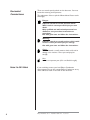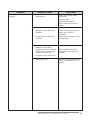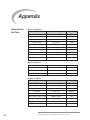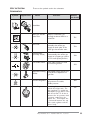
1
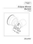
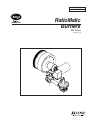
Installation Guide No.110 7/1/03 RatioMatic Burners RM Series Version 3.10 COPYRIGHT Copyright 2003 by Eclipse, Inc. All rights reserved worldwide. This publication is protected by federal regulation and shall not be copied, distributed, transmitted, transcribed or translated into any human or computer language, in any form or by any means, to any third parties, without the express written consent of Eclipse, Inc., Rockford, Illinois, U.S.A. DISCLAIMER NOTICE We reserve the right to change the construction and/or configuration of our products at any time without being obliged to adjust earlier supplies accordingly. The material in this manual is believed adequate for the intended use of the product. If the product, or its individual modules or procedures, are used for purposes other than those specified herein, confirmation of their validity and suitability must be obtained. Eclipse, Inc. warrants that the material itself does not infringe any United States patents. No further warranty is expressed or implied. We have made every effort to make this manual as accurate and complete as possible. Should you find errors or omissions, please bring them to our attention so that we may correct them. In this way we hope to improve our product documentation for the benefit of our customers. Please send your corrections and comments to our Documentation Manager. LIABILITY AND WARRANTY It must be understood that Eclipse’s liability for its products, whether due to breach of warranty, negligence, strict liability, or otherwise, is limited to the furnishing of such replacement parts and Eclipse will not be liable for any other injury, loss, damage or expenses, whether direct or consequential, including but not limited to loss of use, income of or damage to material arising in connection with the sale, installation, use of, inability to use or the repair or replacement of Eclipse’s products. Any operation expressly prohibited in this Guide, any adjustment, or assembly procedures not recommended or authorized in these instructions shall void the warranty. 2 Eclipse RatioMatic v3.10 - Installation Guide No. 110, 7/1/03 About this manual AUDIENCE This manual has been written for people who are already familiar with all aspects of a nozzle-mix burner and its add-on components, also referred to as “the burner system.” These aspects are: • installation • use • maintenance. The audience is expected to have had experience with this kind of equipment. RATIOMATIC DOCUMENTS Installation Guide No. 110 • This document RatioMatic Data Sheets, Series 110 • Available for individual RM models • Required to complete installation Design Guide No. 110 Used with Data Sheet to design burner system RatioMatic Price List No. 110 Used to order burners RELATED DOCUMENTS • • EFE 825 (Combustion Engineering Guide) Eclipse Bulletins and Info Guides: 710, 732, 742, 760, 818, 832, 852, 854, 856, 610, 620, 630, 826, 820, 930, I-354. Purpose The purpose of this manual is to ensure the installation and adjustment of a safe, effective and trouble-free combustion system. Eclipse RatioMatic v3.10 - Installation Guide No. 110, 7/1/03 3 DOCUMENT CONVENTIONS There are several special symbols in this document. You must know their meaning and importance. The explanation of these symbols follows below. Please read it thoroughly. Danger: Indicates hazards or unsafe practices which WILL result in severe personal injury or even death. Only qualified and well trained personnel are allowed to carry out these instructions or procedures. Act with great care and follow the instructions. Warning: Indicates hazards or unsafe pratices which could result in severe personal injury or damage. Act with great care and follow the instructions. Caution: Indicates hazards or unsafe practices which could result in damage to the machine or minor personal injury, Act carefully. Note: Indicates an important part of the text. Read thoroughly. HOW TO GET HELP 4 If you need help, contact your local Eclipse Combustion representative. You can also contact Eclipse Combustion at any of the addresses listed on the back of this document. Eclipse RatioMatic v3.10 - Installation Guide No. 110, 7/1/03 Table of Contents About this manual . . . . . . . . . . . . . . . . . . . . . . . . . . Audience . . . . . . . . . . . . . . . . . . . . . . . . . . . . . . . . . . . . RatioMatic Documents . . . . . . . . . . . . . . . . . . . . . . . . . Related Documents . . . . . . . . . . . . . . . . . . . . . . . . . . . . Document Conventions . . . . . . . . . . . . . . . . . . . . . . . . How to Get Help . . . . . . . . . . . . . . . . . . . . . . . . . . . . . 3 3 3 3 4 4 Table of Contents . . . . . . . . . . . . . . . . . . . . . . . . . . . 5 1 Introduction . . . . . . . . . . . . . . . . . . . . . . . . . . . . . . . . 6 Product Description . . . . . . . . . . . . . . . . . . . . . . . . . . . 6 2 Safety . . . . . . . . . . . . . . . . . . . . . . . . . . . . . . . . . . . . . . Capabilities . . . . . . . . . . . . . . . . . . . . . . . . . . . . . . . . . . . Operator Training . . . . . . . . . . . . . . . . . . . . . . . . . . . . . Replacement Parts . . . . . . . . . . . . . . . . . . . . . . . . . . . . 7 8 8 8 3 Installation . . . . . . . . . . . . . . . . . . . . . . . . . . . . . . . . . . Handling and Storage . . . . . . . . . . . . . . . . . . . . . . . . . . . Approvals of Components . . . . . . . . . . . . . . . . . . . . . . Pre-installation Checklist . . . . . . . . . . . . . . . . . . . . . . . Burner . . . . . . . . . . . . . . . . . . . . . . . . . . . . . . . . . . . . . . Gas Piping . . . . . . . . . . . . . . . . . . . . . . . . . . . . . . . . . . . . Check List After Installation . . . . . . . . . . . . . . . . . . . . . 9 9 9 11 11 13 15 4 Adjustment, Start & Stop . . . . . . . . . . . . . . . . . . . . Step 1: Reset the system . . . . . . . . . . . . . . . . . . . . . . . Step 2: Set low fire air . . . . . . . . . . . . . . . . . . . . . . . . . Step 3: Ignite the burner . . . . . . . . . . . . . . . . . . . . . . . Step 4: Set low fire gas (if required) . . . . . . . . . . . . . . Step 5: Verify settings . . . . . . . . . . . . . . . . . . . . . . . . . . 16 16 18 19 24 26 Maintenance & Troubleshooting . . . . . . . . . . . . . . Maintenance . . . . . . . . . . . . . . . . . . . . . . . . . . . . . . . . . . Monthly Checklist . . . . . . . . . . . . . . . . . . . . . . . . . . . . . Yearly Checklist . . . . . . . . . . . . . . . . . . . . . . . . . . . . . . . Troubleshooting Procedures . . . . . . . . . . . . . . . . . . . . 27 27 27 28 29 5 Appendix . . . . . . . . . . . . . . . . . . . . . . . . . . . . . . . . . . . 32 Conversion Factors . . . . . . . . . . . . . . . . . . . . . . . . . . . . 32 Key to System Schematics . . . . . . . . . . . . . . . . . . . . . . 33 Eclipse RatioMatic v3.10 - Installation Guide No. 110, 7/1/03 5 Introduction PRODUCT DESCRIPTION 1 The RatioMatic Version 3.10 is a nozzle-mix type burner designed for direct air heating, indirect air heating, and oven applications up to 1800° F. (1000° C.) The burner package includes a combustion air blower and an air:gas ratio regulator to fire over a wide gas turndown range at a controlled ratio. The burner is designed for: • efficient ratio controlled combustion • reliable burner operation • simple burner adjustment • direct spark ignition • multiple fuel capability A wide variety of options and configurations are available due to the modular design of the burner. The RatioMatic Burner 6 Eclipse RatioMatic v3.10 - Installation Guide No. 110, 7/1/03 Safety INTRODUCTION SAFETY 2 This section is provided as a guide for the safe operation of the RatioMatic burner system. All involved personnel should read this section carefully before operating this system. Danger: The RatioMatic burners, described herein, are designed to mix fuel with air and burn the resulting mixture. All fuel burning devices are capable of producing fires and explosions if improperly applied, installed, adjusted, controlled, or maintained. Do not bypass any safety feature; fire or explosion could result. Never try to light a burner if it shows signs of damage or malfunction. Warning: The burner might have HOT surfaces. Always wear protective clothing when approaching the burner. Note: This manual provides information in the use of these burners for their specific design purpose. Do not deviate from any instructions or application limits described herein without written advice from Eclipse Combustion. Read the entire manual before attempting to start this system. If you do not understand any part of the information contained in this manual, contact your local Eclipse representative or Eclipse Combustion before continuing. Eclipse RatioMatic v3.10 - Installation Guide No. 110, 7/1/03 7 CAPABILITIES 8 Only qualified personnel, with good mechanical aptitude and experience with combustion equipment, should adjust, maintain, or troubleshoot any mechanical or electrical part of this system. OPERATOR TRAINING The best safety precaution is an alert and trained operator. Train new operators thoroughly and have them demonstrate an adequate understanding of the equipment and its operation. A regular retraining schedule should be administered to ensure operators maintain a high degree of proficiency. REPLACEMENT PARTS Order replacement parts from Eclipse Combustion only. All Eclipse Combustion approved, customer supplied valves or switches should carry UL, FM, CSA, CGA, and/or CE approval, where applicable. Eclipse RatioMatic v3.10 - Installation Guide No. 110, 7/1/03 Installation INTRODUCTION HANDLING AND STORAGE 3 In this chapter you will find information and instructions needed to install the burner and system components. Handling Inspect the system, being sure the components are clean and free of damage. Use the appropriate support and handling equipment when lifting the burner. Protect all components on the system from weather, damage, dirt and moisture. Protect the system and its components from excessive temperatures and humidity. Storage When storing the system for an extended period Eclipse recommends placing it in a cool, clean, dry room. Keep all the system components stored in their original packaging as long as possible. APPROVALS OF COMPONENTS Limit controls and safety equipment All limit controls and safety equipment must comply with all applicable local codes and/or standards, which may include: • NFPA Standard 86 • NFPA Standard 86C • UL • FM • CGA • EN 746-2 Electrical wiring All electrical wiring must comply with all applicable local codes and/or standards, which may include: • NFPA Standard 70 • ANSI-C11981 • EN 746-2 Eclipse RatioMatic v3.10 - Installation Guide No. 110, 7/1/03 9 Gas piping All gas piping must comply with all applicable local codes and/ or standards, which may include: • NFPA Standard 54 • ANSI Z223 • EN 746-2 Where to get the standards The NFPA Standards are available from: National Fire Protection Agency Batterymarch Park Quincy, MA 02269 The ANSI Standards are available from: American National Standard Institute 1430 Broadway New York, NY 10018 The UL Standards are available from: 333 Pfingsten Road Northbrook, IL 60062 The FM Standards are available from: 1151 Boston-Providence Turnpike P.O. Box 9102 Norwood, MA 02062 The CGA Standards are available from: 55 Scarsdale Road Toronto, Ontario Canada M3B 2R3 Information on the EN standards, and where to get the standards is available from: Comité Européen de Normalisation Strassartstraat 36 B-1050 Brussels Comité Européen de Normalisation Electronique Strassartstraat 36 B-1050 Brussels 10 Eclipse RatioMatic v3.10 - Installation Guide No. 110, 7/1/03 PRE-INSTALLATION CHECKLIST Air Supply Provide an opening in the burner room of at least one square inch per 4000 BTU/hr (6 cm2 per 1 kW) to supply the burner intake with fresh, outdoor, combustion air. If there are corrosive fumes or materials in the surrounding air, find an uncontaminated source to supply air to the burner. Exhaust Do not allow exhaust gases to accumulate in the work area. Provide a means for exhausting these gases from the building. Access Install the burners so they may be easily accessed for inspection and maintenance. Environment Be sure the burner operating environment matches the original operating specifications. Check the following items: • voltage, frequency, and stability of electrical power • fuel type and fuel supply pressure • adequate fresh, clean, combustion air • humidity, altitude, and temperature of the supply air • presence of damaging corrosive gases in the air • prevent direct exposure to water. BURNER Minimum 1/4" (6mm) space per side Combustor Chamber Opening Provide an opening in the chamber wall at least ½” (12mm) larger in diameter than the outside diameter of the combustor, or ½” (12mm) larger in height and width than the refractory block. (1/4” - 6mm per side) Provide an accessible pressure tap on the chamber wall to measure the pressure inside the firing chamber. The pressure tap should be located near the burner. Chamber wall “C” Mounting Pattern Attach four mounting bolts to the chamber wall. Position these bolts to match the clearance holes (C) on the burner mounting flange. Refer to the appropriate RatioMatic data sheet. Eclipse RatioMatic v3.10 - Installation Guide No. 110, 7/1/03 11 INSTALLATION (CONTINUED) 4 NOZZLE POSITION 45 Minimum Chamber insulation 2 Chamber Wall Chamber Wall Make sure the chamber wall o is strong enough to support the weight of the burner q. If necessary, reinforce the mounting area. If the chamber insulation extends beyond the nozzle position of the burner, taper the insulation around the combustor at a minimum 45° angle. Refer to data sheets to determine the position of the nozzle relative to the chamber wall. Burner Mounting Mount burner to chamber wall using four (4) customer supplied nuts and lock washers. 1 Both Alloy and Silicon Carbide (SiC) Combustor 1. Be sure gasket n is installed between burner q and chamber wall o. 2. Pack fiber insulation around the combustor to a depth not beyond the nozzle position, as illustrated. NOZZLE POSITION 4 Fiber insulation Chamber insulation 2 Alloy Combustor Caution: Placing insulation around the combustor beyond the burner nozzle position will decrease combustor life. 3. No gasket is supplied or required between burner and combustor. 1 Silicon Carbide (SiC) Combustor only 4 5 NOZZLE POSITION Caution: SiC combustor 5 is fragile. Handle with care. Fiber insulation 3 6 2 Chamber insulation Silicon Carbide (SiC) Combustor 12 If the SiC combustor is not already attached to the burner, be sure gasket p is installed between the SiC combustor r and flange s. Tighten the screws which hold the flange s to the burner 4 evenly. Do not over tighten. Caution: When replacing SiC combustor: • be sure gasket p is installed • tighten screws evenly • do not use excessive force Eclipse RatioMatic v3.10 - Installation Guide No. 110, 7/1/03 7 11 1 NOZZLE POSITION 4 Refractory Block 1. Be sure the gasket n is installed between the burner q and the block holder t. 2. Be sure the gasket u is installed between the block holder t and the chamber wall o. 3. Support the weight of the refractory block v with hard brick work w. Fill space around the block v with soft gasket material 11 . 8 2 9 10 Refractory Block GAS PIPING Burner Piping The burner is factory assembled and shipped as ordered. Note: If it is necessary to redirect piping, be sure the: • ratio regulator spring column n is pointing up. • arrow on the ratio regulator points in the direction of gas flow. • integral fuel orifice and o-rings o are re-installed. • same straight run of pipe p remains between the ratio regulator and the burner . Burner Piping Supply Piping Inlet pressure to the ratio regulator must stay within specified limits. Refer to the appropriate RatioMatic data sheet. • Locate the valve train close to the burner. The gas must reach the burner during the fixed trial for ignition. • Sufficiently size shut off valves in the valve train. • Make sure piping is large enough. • Minimize piping elbows. Eclipse RatioMatic v3.10 - Installation Guide No. 110, 7/1/03 13 Main gas shut-off valve train 1 NC 2 NC 4 5 3 Bypass Start Gas Piping Bracket Pipe Union Bypass Start Gas Piping (optional) Install the piping as shown in the schematics referred to in Chapter 3 of the RatioMatic Design Guide No. 110 using the following guidelines. • Locate the start gas solenoids 1 close to the burner. The gas must reach the burner during the trial for ignition period. • Minimize piping elbows. • Install an adjustable limiting orifice (ALO) 2 for start gas adjustment. Refer to Bulletin 728 and 730 for further information. • Include a straight run of pipe at least 8 inches long 3 before (upstream from) the start gas orifice 5 (optional) and at least 4 inches long 4 after (downstream from) the start gas orifice. Pipe Connections • Installation of a pipe union in the gas line is recommended to simplify burner removal. • Use of flexible pipe is optional. Note: Flexible pipe causes higher pressure drops than standard pipe. Consider this when sizing your gas lines. Pipe Connections Piping Support Use brackets or hangers to support the gas piping. If you have questions, consult your local gas company. BV Shaft Set Screws Motor Shaft Control Motor Install a control motor to modulate the air butterfly valve if not previously installed on the burner. Control Motor Washers Coupling Note: Be sure the control motor shaft and air butterfly valve shaft are aligned properly. If using an Eclipse Actuator Mounting Parts Kit, the supplied washers may be used as shims (stacked 0, 1, or 2 high) to ensure proper alignment. Additionally, a flexible coupling can be used to handle minor misalignment. Control Motor 14 Eclipse RatioMatic v3.10 - Installation Guide No. 110, 7/1/03 CHECK LIST AFTER INSTALLATION To verify the system was properly installed, perform the following checks: 1. Be sure there are no leaks in the gas lines. 2. Be sure all the components contained in the flame monitoring and control system are properly installed. This includes verifying that: • all the switches are installed in the correct locations. • all wiring, pressure, and impulse lines are properly connected. 3. Be sure all components of the spark ignition system are installed and functioning properly. 4. Be sure the blower rotates in the proper direction. If the rotation is incorrect, have a qualified electrician rewire the blower to rotate in the proper direction. 5. Be sure all valves are installed in the proper location and correctly oriented relative to the flow direction. Eclipse RatioMatic v3.10 - Installation Guide No. 110, 7/1/03 15 Adjustment, Start & Stop INTRODUCTION 4 In this chapter, you will find instructions on how to adjust, start, and stop the burner system. Become familiar with burner control methods before attempting to make adjustments.. Danger: The RatioMatic burners, described herein, are designed to mix fuel with air and burn the resulting mixture. All fuel burning devices are capable of producing fires and explosions if improperly applied, installed, adjusted, controlled, or maintained. Do not bypass any safety feature; fire or explosion could result. Never try to light a burner if it shows signs of damage or malfunction. ADJUSTMENT Adjustment steps: 1. Reset the system 2. Set low fire air 3. Ignite the burner 4. Set low fire gas 5. Verify settings Step 1: Reset the system Reset procedure: 1. Set the low gas pressure switch to 20% below the “Main gas inlet pressure” range as specified in the appropriate data sheet. 2. Set the high gas pressure switch to 20% above the “Main gas inlet pressure” range as specified in the appropriate data sheet. 3. Close all the burner gas valves, manual and automatic. 4. Try to ignite the burner; be sure the flame monitoring system indicates a flame failure. 16 Eclipse RatioMatic v3.10 - Installation Guide No. 110, 7/1/03 Step 1: Reset system (continued) 5. Activate the pressure switches and other limit interlocks. Be sure the switches fail as intended in the event of a power failure. Danger: If simulated limits or simulated flame failures do not shut down the fuel system within the required failure response time, immediately correct the problem before proceeding. 6. If the burner is firing into a duct or chamber with a circulating fan, start the fan to produce a full process air flow past the burner. 7. Adjust main gas inlet pressure to the ratio regulator within the range specified in the appropriate data sheet. Warning: Gas inlet pressures must stay within the specified range. Pressure above the specified range can damage the ratio regulator. back Warning: Pressure below the specified range can impair the ability of the ratio regulator to control the gas flow. Operating the system outside the specified range can cause excess fuel consumption and the possible accumulation of unburned fuel in the chamber. In extreme cases, this accumulation of unburned fuel may cause fires or explosions. 8. Verify that the actuator opens the air BV towards the back of the burner as shown. If it doesn’t, refer to the actuator’s literature for instructions on how to reverse the direction. Closed Open Open in this direction only Air BV Eclipse RatioMatic v3.10 - Installation Guide No. 110, 7/1/03 17 Step2: Set low fire air To Chamber Tap C Low fire air adjustment procedure: 1. Start combustion air blower. 2. Drive control motor to low fire position. 3. Measure air differential pressure between tap (C ) and combustion chamber. Note: The pressure tap is in the open position when the screw inside the tap is unscrewed approximately 1/2 turn. Do not remove screw. Be sure to tighten pressure tap screw clockwise to the closed position after pressure measurements have been taken. 4. Set low fire air. a. Loosen the set screw n on burner side of coupling o. Air Differential Pressure Note: There is a slot in the end of the BV shaft that is parallel to the air damper. This slot is used for visual indication of the BV position. The BV is closed when the shaft slot is perpendicular to the direction of air flow through the BV. b. Rotate air BV shaft to fully closed position. (Holes in BV damper will supply low fire air.) 1 2 Air BV Adjustment Note When firing into a positive chamber pressure, rotate the air BV from closed position in the direction of actuator travel to obtain a minimum 0.2” w.c. (0,5 mbar) air differential pressure. c. Hold BV shaft firmly in place and tighten set screw 1 . Note: High fire air adjustment is not required if burner is firing into a neutral pressure chamber and a 90° travel control motor is used. It may be necessary to limit control motor stroke to less than 90° if firing into a large positive or negative chamber. Contact your Eclipse Combustion representative for further information. BV shaft shown in closed position Air BV Shaft 18 5. Verify high fire air a. Drive control motor to high fire, full open. b. Compare the high fire air differential pressure between tap (C) and the combustion chamber to the appropriate data sheet chart “Air ∆P vs. Air Flow.” If high fire air is insufficient, refer to Section 5, Troubleshooting and Maintenance, in this document. 6. Return the control motor to the low fire position. 7. Close the pressure taps. Eclipse RatioMatic v3.10 - Installation Guide No. 110, 7/1/03 Step3: Ignite the burner Ignition procedure: Warning: This procedure is written with the assumption the burner has a flame monitoring control system installed and operating. A proper purge cycle must be part of the system and purge timing should not be bypassed. Determine system layout and use the applicable ignition procedure. Low fire start without high turndown option. Procedure “A”, page 20 Low fire start with high turndown option. Procedure “B”, page 21 Ratio regulator with bypass adjusting screw Main gas shut-off valve train Main gas shut-off valve train Note: The ratio regulator is factory set. Use Procedure “A” only if burner does not ignite or requires further adjustment. Bypass start gas without fuel orifice meter Procedure “C”, page 22 Note: The RatioMatic burner with high turndown option includes a ratio regulator with internal bypass adjustment. Bypass start gas with fuel orifice meter Procedure “D”, page 23 Main gas shut-off valvetrain NC NC Main gas shut-off valve train NC NC Eclipse RatioMatic v3.10 - Installation Guide No. 110, 7/1/03 19 Step3: Ignite the burner Procedure A: Low fire start without high turndown option. Low fire start without high turndown option: Main gas shut-off valve train CW for more gas Bias Adjusting Screw Ratio Regulator 1. Drive control motor to low fire. 2. Be sure combustion air blower is running. 3. Verify bias adjusting screw 1 on ratio-regulator spring column is six full clockwise turns (360° x 6) down from the top (initial setting). 4. Open main gas manual shut off valves. 5. Set system control to stay at low fire during and after ignition sequence. 6. Attempt to ignite burner. 7. If burner does not ignite: a. Attempt to ignite burner again to purge air from the gas piping. b. If burner still does not ignite, turn bias adjusting screw 1 a half turn clockwise to increase gas flow. c. Attempt to ignite burner. d. Repeat steps b and c until burner ignites. If necessary, refer to Chapter 5 for troubleshooting tips. 8. Flame signal strength: Adjust gas flow with bias adjusting screw 1 for lowest gas flow that maintains a stable flame signal: • clockwise, for more fuel • counterclockwise, for less fuel. Note: If viewing the flame, it should be blue with flashes of yellow. The flame should be completely within the combustion tube. When firing propane or butane, a proper low fire flame may have sustained flashes of yellow. 9. Verify low fire flame: a. Shut off gas. When chamber temperature is below 250°F (121°C), shut off combustion air blower. b. Restart combustion air blower and ignite burner. c . Verify repeatability of ignition and low fire flame signal. 20 Eclipse RatioMatic v3.10 - Installation Guide No. 110, 7/1/03 Step3: Ignite the burner Procedure B: Low fire start with high turndown option. Low fire start with high turndown option: Ratio regulator with bypass adjusting screw Main gas shut-off valve train 1. 2. 3. CW for more gas Bias 1 adjusting screw CCW for more gas 2 Internal bypass adjusting screw Ratio Regulator (with internal bypass adjusting screw) Drive control motor to low fire. Be sure combustion air blower is running. Verify bias adjusting screw 1 on ratio-regulator spring column is six full clockwise turns (360° x 6) down from top (initial setting). 4. Open main gas manual shut off valves. 5. Close internal bypass adjusting screw 2 by turning it clockwise to closed position. 6. Set system control to stay at low fire during and after ignition sequence. 7. Attempt to ignite burner. 8. If burner does not ignite: a. Attempt to ignite burner again to purge air from the gas piping. b. If burner still does not ignite, turn bias adjusting screw 1 a half turn clockwise to increase gas flow. c. Attempt to ignite burner. d. Repeat steps b and c until burner ignites. If necessary, refer to Chapter 5 for troubleshooting tips. 9. After burner ignites, slowly decrease gas flow with bias adjusting screw 1. Decrease gas flow until the flame signal becomes erratic. (Refer to flame monitoring relay literature for a description of an erratic flame signal.) 10. If burner has gone out: Repeat ignition sequence. Turn internal bypass adjusting screw 2 a half turn counterclockwise to increase gas flow at each attempt until burner lights. 11. Flame signal strength: Adjust gas flow with internal bypass adjusting screw 2 for lowest gas flow that maintains a stable flame signal: • counterclockwise, for more fuel • clockwise, for less fuel. Note: If viewing the flame, it should be blue with flashes of yellow. The flame should be completely within the combustion tube. When firing propane or butane, a proper low fire flame may have sustained flashes of yellow. 12. Verify low fire flame: a. Shut off gas. When chamber temperature is below 250°F (121°C), shut off combustion air blower. b. Restart combustion air blower and ignite burner. c. Verify repeatability of ignition and low fire flame signal. Eclipse RatioMatic v3.10 - Installation Guide No. 110, 7/1/03 21 Step3: Ignite the burner Procedure C: Bypass start gas without fuel orifice meter. Bypass start gas without fuel orifice meter: 3 Main gas shut-off valvetrain 2 NC NC 1 1. 2. 3. 4. 5. 6. ALO 3 Adjusting Screw CCW for more gas Cap Adjustable Limiting Orifice (ALO) Drive control motor to low fire. Be sure combustion air blower is running. Be sure main gas manual shut off valves are closed. Open manual shut off valve 1 in the bypass. Set the system to operate on bypass gas only. Attempt to ignite burner by energizing spark and bypass gas solenoid valves 2. 7. If burner does not ignite: a. Attempt to ignite burner again to purge air from the gas piping. b. If burner still does not ignite, turn ALO adjusting screw 3 a half turn counterclockwise to increase gas flow. c. Attempt to ignite burner. d. Repeat steps b and c until burner ignites. If necessary, refer to Chapter 5 for troubleshooting tips. 8. Flame signal strength: Adjust bypass gas flow with ALO adjusting screw 3 for lowest gas flow that maintains a stable flame signal: • counterclockwise, for more fuel • clockwise, for less fuel. Note: If viewing the flame, it should be blue with flashes of yellow. The flame should be completely within the combustion tube. When firing propane or butane, a proper low fire flame may have sustained flashes of yellow. 9. Verify bypass flame: a. Shut off gas. When chamber temperature is below 250°F (121°C), shut off combustion air blower. b. Restart combustion air blower and ignite burner. c. Verify repeatability of ignition and low fire flame signal. 22 Eclipse RatioMatic v3.10 - Installation Guide No. 110, 7/1/03 Step3: Ignite the burner Procedure D: Bypass start gas with fuel orifice meter Bypass start gas with fuel orifice meter: Main gas shut-off valve train 3 1. 2. 3. 4. 5. 6. 7. 8. 9. Adjustable Limiting Orifice (ALO) NC 2 NC 4 1 Drive control motor to low fire. Be sure combustion air blower is running. Be sure main gas manual shut off valves are closed. Prepare to measure bypass gas flow at the fuel orifice meter 4. Open manual shut off valve 1 in the bypass. Set the system to operate on bypass gas only. Attempt to ignite burner by energizing spark and bypass gas solenoid valves 2. If burner does not ignite: a. Attempt to ignite burner again to purge air from the gas piping. b. If burner still does not ignite, turn ALO adjusting screw 3 a half turn counterclockwise to increase gas flow. c. Attempt to ignite burner. d. Repeat steps b and c until burner ignites. If necessary, refer to Chapter 5 for troubleshooting tips. Adjust bypass gas flow with ALO adjusting screw 3 to achieve the low fire gas flow indicated on data sheet. Refer to the fuel orifice meter literature for instructions on flow measurement. Note: When firing into negative or fluctuating chamber pressures, a higher bypass gas flow may be necessary. Note: If viewing the flame, it should be blue with flashes of yellow. The flame should be completely within the combustion tube. When firing propane or butane, a proper low fire flame may have sustained flashes of yellow. 10. Verify the bypass gas flame: a. Shut off gas. When chamber temperature is below 250°F (121°C), shut off combustion air blower. b. Restart combustion air blower and ignite burner. c. Verify repeatability of ignition and low fire flame signal. Eclipse RatioMatic v3.10 - Installation Guide No. 110, 7/1/03 23 Step 4: Set low fire gas (Only required if bypass start is used.) Set low fire gas procedure: Warning: This procedure is written with the assumption the burner has a flame monitoring control system installed and operating. A proper purge cycle must be part of the system control and purge timing should not be bypassed. This step is only necessary when bypass start gas is used. Determine the piping method (low fire or bypass) and ratio regulator installed (standard or high turndown), and proceed with the applicable procedure: CW for more gas Bias Adjusting Screw Bypass start gas with standard turndown ratio regulator: 1. Verify bias adjusting screw 1 on ratio regulator spring column is six full clockwise turns (360° x 6) down from the top (initial setting). 2. Open all manual gas shut off valves. 3. Set system control to stay at low fire during and after ignition sequence. 4. Ignite the burner. 5. If burner goes out due to main gas flame failure: Turn bias adjusting screw 1 a half turn clockwise to increase gas flow. Repeat ignition sequence until burner lights. 6. Flame signal strength: Adjust gas flow with bias adjusting screw 1 for lowest gas flow that maintains a stable flame signal: • clockwise, for more fuel • counterclockwise, for less fuel Note: If viewing the flame, it should be blue with flashes of yellow. The flame should be completely within the combustion tube. When firing propane or butane, a proper low fire flame may have sustained flashes of yellow. Ratio Regulator 24 7. Verify low fire flame . a. Drive control motor from low fire and back. Verify low fire and stable flame signal are repeated. b. Turn the burner off and repeat the ignition sequence. Verify low fire and stable flame signal are repeated. Eclipse RatioMatic v3.10 - Installation Guide No. 110, 7/1/03 Step4: Set low fire gas (continued) 1 Bias adjusting screw CW for more gas CCW for more gas 2 Internal bypass adjusting screw Ratio Regulator (with internal bypass adjusting screw) Bypass start gas with high turndown option: 1. Verify bias adjusting screw 1 on ratio regulator spring column is six full clockwise turns (360° x 6) down from the top (initial setting). 2. Open all manual shut off valves. 3. Close internal bypass adjusting screw 2 by turning it clockwise to closed position. 4. Set system control to stay at low fire during and after ignition sequence. 5. Ignite the burner. 6. If burner goes out due to main gas flame failure: Turn bias adjusting screw 1 a half turn clockwise to increase gas flow. Repeat ignition sequence until burner lights. 7. Slowly decrease gas flow with bias adjusting screw 1. Decrease gas flow until the flame signal becomes erratic. (Refer to flame monitoring relay literature for a description of an erratic flame signal.) 8. If burner has gone out: Repeat ignition sequence. Turn internal bypass adjusting screw 2 a half turn counterclockwise to increase gas flow at each attempt until burner lights. 9. Flame signal strength: Adjust gas flow with internal bypass adjusting screw 2 for lowest gas flow that maintains a stable flame signal: • counterclockwise, for more fuel • clockwise, for less fuel. Note: If viewing the flame, it should be blue with flashes of yellow. The flame should be completely within the combustion tube. When firing propane or butane, a proper low fire flame may have sustained flashes of yellow. 10. Verify low fire flame. a. Drive the control motor from low fire and back. Verify low fire and stable flame signal are repeated. b. Turn the burner off and repeat the ignition sequence. Verify low fire and stable flame signal are repeated. Eclipse RatioMatic v3.10 - Installation Guide No. 110, 7/1/03 25 Step5: Verify Settings Setting verification: Note: There are no high fire gas adjustments or air adjustments when firing into a neutral chamber. However, air and gas pressures can be used to verify the burner system is properly adjusted. Tap C Chamber Tap D Tap B 1. With burner lit, drive control motor to high fire. 2. Wait for the chamber to reach normal operating conditions (e.g. chamber temperature, process flows, etc.). 3. Measure high fire fuel differential pressure between tap (B) and tap (D). Compare this to the “Fuel Orifice ∆P vs. Input” graph on the data sheet. 4. Measure high fire air differential pressure between tap (C) and the chamber. Compare this pressure to the “ Air ∆P vs. Air Flow” graph on the data sheet. 5. Drive the control motor to low fire and verify low fire flame signal and flame appearance (if viewing). Note: Gas pressure at low fire will be too low to measure and verify the fuel settings. 6. Cycle burner from high to low several times to check repeatability of settings. 7. Readjust burner if the settings do not repeat as excepted. If necessary, refer to Chapter 5, Maintenance & Troubleshooting. 8. Record all setup data as an aid for future troubleshooting and setup operations. Caution: Do not turn the combustion air blower off until the chamber temperature is below 250°F (121°C). This will prevent hot gases from back flowing into the burner and blower causing damage to the burner. 9. Stop the burner. 26 Eclipse RatioMatic v3.10 - Installation Guide No. 110, 7/1/03 Maintenance & Troubleshooting INTRODUCTION 5 This chapter is divided into two sections: • Maintenance procedures • Troubleshooting guide Preventive maintenance is the key to a reliable, safe and efficient system. The core of any preventive maintenance system is a list of periodic tasks. MAINTENANCE Monthly Checklist Note: These are guidelines only. The customer should make the final determination on maintenance intervals and tasks to be performed while considering the working environment. 1. Inspect the flame sensing devices for good condition and cleanliness. 2. Check for proper air/gas pressures (Refer to the RatioMatic Data Sheets, Series 110). 3. Test all the system alarms for proper response signals. 4. Check and clean igniter electrodes. 5. Check the air control valve for smooth, trouble free operation and adjustment. 6. Check for the proper operation of ventilating equipment. 7. Test the interlock sequence on all safety equipment. Manually force each interlock to intentionally fail while at the same time noting if related equipment closes or stops as specified by the manufacturer. Test the flame safeguard by manually shutting off the gas to the burner. 8. Test the manual gas shut off cocks for proper operation. 9. Clean and/or replace the combustion air blower filter. 10. Inspect and clean the combustion air blower rotor. Eclipse RatioMatic v3.10 - Installation Guide No. 110, 7/1/03 27 Yearly Checklist 1 4 28 1. Leak test the safety shut-off valves for tightness of closure. 2. Test the pressure switch settings by checking the switch movements against pressure settings and comparing these with the actual impulse pressure. 3. Visually check igniter cable and connectors. 4. Inspect impulse piping for leaks. 5. Remove, clean, and inspect all burners. 6. Remove and clean the orifice plate 4 . 7. Be sure the following components are not damaged or distorted: • the burner nozzle. • the igniter. • the flame sensors. • the combustion tube or block. The nozzle and combustion tube/block can be inspected without removing the burner from the chamber wall or entering the chamber. Perform the following: a. Shut the burner off and manually close the main gas shut off cocks. b. Allow the chamber temperature to cool down to 250°F (121°C). c. Disconnect the gas piping at a union or the gas inlet flange 1 provided on the burner. d. Remove the four bolts 2. e. Remove the rear cover 3 from the burner housing 4. f. To re-assemble, follow this sequence in the reverse order. Eclipse RatioMatic v3.10 - Installation Guide No. 110, 7/1/03 TROUBLESHOOTING PROCEDURES PROBLEM Start-up sequence runs but burner does not light. POSSIBLE CAUSE SOLUTION No ignition: • There is no power to the ignition transformer. No ignition: • Open circuit between the ignition transformer and the igniter. No ignition: • The igniter needs cleaning. No ignition: • The igniter is not correctly grounded to the burner. Restore the power to the ignition transformer. No ignition: • Igniter insulator is broken. Igniter is grounding out. Not enough gas: • The gas pressure going into the ratio regulator is too low. Not enough gas: • The impulse line to the ratio regulator is leaking. Not enough gas: • The pilot adjusting valve or bypass valve is not open far enough. Not enough gas: • Start gas solenoid valve does not open. Not enough gas: • Gas valve does not open. Inspect the igniter. Replace if broken. Not enough gas: • Ratio regulator is incorrectly set. Adjust the ratio regulator to the proper setting. Repair or replace the wiring to the igniter. Clean the igniter. Clean the threads on the igniter and the burner. NOTE: Do not apply grease to the threads on the igniter. Check the start-up settings. Measure the gas pressures and adjust where necessary. Repair any leaks. Adjust bypass or low fire gas. Check the solenoid valve coil for proper operation. Replace it if necessary. Check the wiring to the automatic gas shut-off valve. Check the output from the flame safeguard. Open manual gas cock. Eclipse RatioMatic v3.10 - Installation Guide No. 110, 7/1/03 29 PROBLEM Start-up sequence runs but burner does not light. (continued) The low fire flame is weak or unstable. The burner goes out when it cycles to high fire. 30 POSSIBLE CAUSE SOLUTION No flame signal: •Broken flamerod •Dirty UV scanner lens Inspect and clean sensor Replace if necessary No flame signal: • Spark plug and flamerod reversed Exchange spark plug/flamerod or their wiring Too much gas: • Wrong or missing burner fuel orifice. Check RatioMatic Data Sheets, Series 110 for fuel orifice and the given fuel. • Not enough gas flowing to the burner. Adjust the ratio regulator to increase the gas flow. • Not enough air. Check for proper blower rotation. Check air filter for blockage. Compensate for chamber by opening the low fire air butterfly valve position. • Not enough gas pressure into the ratio regulator. • Loading line to the ratio regulator is leaking. Check the start-up settings. Measure the gas pressures and adjust them where necessary. Check for valve train pressure loss. Repair the leak in the loading line. The burner is erratic and does not respond to adjustment. Internal damage to the burner: • Some parts inside the burner are loose, dirty, or burned out. Contact your Eclipse representative or Eclipse Combustion for further information. The burner is unstable or produces soot, smoke, or excessive carbon monoxide. • The air/gas ratio is out of adjustment. Measure all the gas pressures and air pressures. Compare these pressures to the documented initial start-up settings and adjust them where necessary. The burner cannot achieve full capacity. • Air filter is blocked. Clean or replace the air filter. • Gas pressure going into the ratio regulator is too low. Adjust the gas pressure. Eclipse RatioMatic v3.10 - Installation Guide No. 110, 7/1/03 PROBLEM Cannot initiate a start sequence. POSSIBLE CAUSE SOLUTION • Air pressure switch has not made contact. Check air pressure switch adjustment. Check air filter. Check blower rotation. Check outlet pressure from blower. • High gas pressure switch has activated. • Low gas pressure switch has activated. Check incoming gas pressure. Adjust gas pressure if necessary. Check pressure switch setting and operation. • • Malfunction of the flame safeguard system (e.g., shortedout flame sensor or electrical noise in the sensor line). No power to the control unit. • Main power is off. Have a qualified electrician troubleshoot and correct the problem. Be sure the main power to the system is switched to the “on” position. Eclipse RatioMatic v3.10 - Installation Guide No. 110, 7/1/03 31 Appendix CONVERSION FACTORS Metric to English. From To 3 Multiply By 3 cubic meter (m ) cubic foot (ft ) 35.31 cubic meter/hour (m /h) cubic foot/hour (cfh) 35.31 degrees Celsuis (ºC) degrees Fahrenheit (ºF) (ºC x 1.8) + 32 kilogram (kg) pound (lb) 2.205 kilowatt (kW) BTU/hr 3414 meter (m) foot (ft) 3.28 millibar (mbar) inches water column (“w.c.) 0.401 millibar (mbar) pounds/sq in (psi) 14.5 x 10⁻³ millimeter (mm) inch (in) 3.94 x 10⁻² MJ/m3 (normal) BTU/ft3 (standard) 2.491 x 10⁻² kiloPascals (kPa) millibar (mbar) 10 meter (m) millimeter (mm) 1000 millibar (mbar) kiloPascals (kPa) 0.1 millimeter (mm) meter (m) 0.001 From To Mulitply By BTU/hr kilowatt (kW) 0.293 x 10⁻³ cubic foot (ft3) cubic meter (m3) 2.832 x 10⁻² degrees Fahrenheit (ºF) degrees Celsius (ºC) (ºF – 32) ÷ 1.8 foot (ft) meter (m) 0.3048 inches (in) millimeter (mm) 25.4 inches water column (“wc) millibar (mbar) 2.49 pound (lb) kilogram (kg) 0.454 pounds/sq in (psi) millibar (mbar) 68.95 BTU/ft3 (standard) MJ/m3 (normal) 40.14 3 Metric to Metric. English to Metric. 32 Eclipse RatioMatic v3.10 - Installation Guide No. 110, 7/1/03 KEY TO SYSTEM SCHEMATICS Symbol Appearance These are the symbols used in the schematics. Name Remarks Bulletin/ Info Guide RatioMatic NC Main Gas Shutoff Valve Train Eclipse Combustion, Inc. strongly endorses NFPA as a minimum Gas Cock Gas cocks are used to manually shut off the gas supply on both sides of the main gas shut-off valve train. 710 Solenoid Valve (normally closed) Solenoid valves are used to automatically shut off the gas supply on a bypass gas system or on small capacity burners. 760 Fuel Orifice Meter Fuel orifice meters are used to measure gas flow. Adjustable Limiting Orifice Adjustable limiting orifices are used for fine adjustment of gas flow. Pressure Regulator A pressure regulator reduces gas pressure to a stable, usable pressure. Ratio Regulator A ratio regulator is used to control the air/gas ratio. The ratio regulator is a sealed unit that adjusts the gas flow in ratio with the air flow. To do this, it measures the air pressure with a pressure sensing line, the impulse line. This impulse line is connected between the top of the ratio regulator and the burner body. Eclipse RatioMatic v3.10 - Installation Guide No. 110, 7/1/03 756 910 684 742 33 KEY TO SYSTEM SCHEMATICS (CONTINUED) Symbol Appearance Name Remarks Pressure Taps Impulse Line 34 Eclipse RatioMatic v3.10 - Installation Guide No. 110, 7/1/03 Bulletin/ Info Guide Offered By: Burnerparts.com 2011 Williamsburg Road Richmond, Virginia 23231 Phone (804) 236-3881 Fax (804) 236-3882 www.burnerparts.com