1
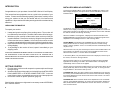
DNR V SERIES DISPLAY
25 inch
160 FIRST STREET S.E.
ST. PAUL, MN 55112-7894
PHONE 651-633-1742
FAX: 651-633-1065
www.dotronix.com
User’s Manual
Publication No. 01082 Rev A
PRECAUTIONS
This monitor contains circuits and components designed to meet specific
performance and safety requirements. No component changes may be
made without the written permission of the manufacturer.
Dotronix Limited Warranty
Dotronix warrants that for one (1) year from date original purchase, it
will, at its option, repair, replace or refund the purchase price of any product which it
manufactured that proves defective in material or workmanship in normal use and service.
To prevent electrical shock, do not attempt to disassemble the monitor.
There are no user-serviceable parts inside. Servicing, if required, should be
performed only by qualified service technicians familiar with the equipment
and safety procedures. Servicing by unauthorized personnel may be
dangerous and will void the warranty.
To obtain service under this Warranty, contact Dotronix Inc. at the address below, within
one (1) year of original purchase, to receive a Return Material Authorization (RMA) number.
Then ship the product believed to be defective, transportation prepaid, for inspection.
Do not use this monitor beyond its temperature and humidity range. This unit
is designed for indoor use. Ambient temperature range must not be above
113oF or below 32oF. Avoid using this monitor when the humidity is either
above 95% or less than 5%. Do not block the ventilation slots on the rear
side of the monitor. Allow for normal ventilation.
For products supplied without a frame (Less CRT and Printed Circuit Board Mounting), the
buyer must inspect the products within ten (10) days of receipt. After ten (10) days have
lapsed, there shall be no warranty coverage for broken or damaged parts, or misalignment
(i.e. broken torque seals where used). The products will be packed to allow Buyer to test
the unit within its packing carrier.
Position the monitor to avoid direct sunlight on the picture tube. Generally,
adjust the monitor for proper lighting and monitor position to minimize
undesirable reflections.
All rights reserved. No part of this publication may be reproduced, stored in a retrieval system, or transmitted, in any form
or by any means, mechanical, photocopying, recording or
otherwise, without the prior written permission of Dotronix, Inc.
No patent liability is assumed with respect to the use of the
information contained herein. Where every precaution has
been taken in the preparation of this manual, Dotronix, Inc. and
the author assume no responsibility for errors or omissions.
Neither is any liability assumed for damage resulting from the
use of the information contained herein.
Specifications are subject to change due to technological
progress.
© Copyright 2001, Dotronix, Inc.
Publication No.01082 Rev. A
160 First Street S.E.
St. Paul, MN 55112-7894, USA
2
Dotronix shall not be responsible for unauthorized returns that do not list the RMA number
and quantity returned on the outside of the shipping container (i.e. on packing list in plain
view).
This Warranty applies only to goods manufactured by Dotronix Inc. Various component
parts manufactured by others (such as cathode ray tubes, semi-conductors, and fuses ) are
covered by the separate warranty of their manufacturers. Where Dotronix, Inc. warranty
differs, only the warranty of the original component part manufacturer is offered. Of course,
the Dotronix warranty does not apply to CRT's that are scratched, broken, burned or have
imperfections in any special coatings. It also does not apply to products which have been
altered, damaged, abused, or subjected to misuse, or repaired by anyone other than an
authorized Dotronix repair person.
These displays require DHHS traceability under sub-part E, Section 1002.40 of the
Regulations for the Administration and Enforcement of the Radiation Control for Health and
Safety Act of 1968. It is the customer's responsibility to maintain records that satisfy this
requirement.
THE TERMS OF THIS WARRANTY CONSTITUTES THE BUYER'S SOLE AND EXCLUSIVE REMEDY AGAINST DOTRONIX. THERE IS NO IMPLIED WARRANTY OF MERCHANTABILITY OR FITNESS FOR A PARTICULAR PURPOSE. UNDER NO CIRCUMSTANCE SHALL DOTRONIX BE LIABLE FOR INCIDENTAL AND CONSEQUENTIAL
DAMAGES, OR IN ANY AMOUNT BEYOND THE REPLACEMENT COST OF THE
ALLEGEDLY DEFECTIVE PART, REGARDLESS OF THE THEORY OF RECOVERY.
All products returned to Dotronix must include:
1. A tag or label on each unit with a description of the defect or reason for return,
or identify each unit on the packing list by serial number and defect.
2. A packing list attached to the outside of the shipping container showing the
Return Authorization Number (RMA) and the quantity returned.
Products returned that are not identified in accordance with the above procedure will
be refused and returned at Buyer's expense.
To obtain a Return Material Authorization (RMA) number contact:
DOTRONIX INC.
160 First Street S.E. • St. Paul • Minnesota • 55112-7894
Phone 651-633-1742 • FAX 651-633-1065
23
INDEX
AVAILABLE MENUS ............................................................................. 16
BASIC MENU OPERATION .................................................................. 16
CRT COATINGS OPTION ..................................................................... 13
GETTING STARTED ............................................................................... 8
IMPORTANT SAFETY INSTRUCTIONS ................................................. 3
INTRODUCTION ..................................................................................... 8
MECHANICAL DIMENSIONS-CUBE ................................................... 10
MENU-AVAILABLE ............................................................................... 16
MENU-BASIC OPERATION .................................................................. 16
MENU-SERVICE ................................................................................... 17
PRECAUTIONS ...................................................................................... 2
REAR CONTROLS ............................................................................... 11
REGULATORY NOTICES ....................................................................... 7
REMOTE CONTROL............................................................................. 15
SAFETY WARNINGS .............................................................................. 3
SERVICE MENU ................................................................................... 17
SERVICE MODULE INPUT ................................................................... 14
SETUP MENU ....................................................................................... 12
SPECIFICATIONS ................................................................................... 9
WALL INSTALLATIONS ....................................................................... 12
WARRANTY, DOTRONIX LIMITED ...................................................... 23
SAFETY WARNINGS
SAFETY TIPS
Refer to the “Important Safety Instructions” section of this operating guide
for important safety considerations.
WARNING
TO PREVENT FIRE OR SHOCK HAZARDS, DO NOT EXPOSE THIS
PRODUCT TO RAIN OR MOISTURE.
NOTE TO CABLE TV SYSTEM INSTALLER
This reminder is provided to call the cable TV system installer’s attention
to Article 820-40 of the National Electrical Code (U.S.A.). The code
provides guidelines for proper grounding and, in particular, specifies that
the cable ground shall be connected to the grounding system of the
building, as close to the point of the cable entry as practical.
IMPORTANT SAFETY INSTRUCTIONS
Your product has been manufactured and tested with your safety in mind.
However, improper use can result in potential electrical shock or fire
hazards. To avoid defeating the safeguards that have been built into your
new product, please read and observe the following safety points when
installing and using your new product, and save them for future reference.
Observing the simple precautions discussed in this section of the operating guide can help you get many years of enjoyment and safe operation
from your new product.
1. Read Instructions
Read all the safety and operating instructions before operating
the product.
22
3
SAFETY WARNINGS
2. Follow Instructions
Follow all operating and use instructions.
3. Retain Instructions
Keep the safety and operating instructions for future reference.
4. Heed Warnings
Follow all warnings on the product and in the operating instructions.
5. Cleaning
Unplug this product from the wall outlet before cleaning. Do not use liquid
cleaners or aerosol cleaners. Use a damp cloth for cleaning.
6. Water and Moisture
Do not use this product near water-for example, near a bath tub, wash
bowl, kitchen sink, laundry tub, in a wet basement, or near a swimming
pool.
7. Accessories
Do not place this product on an unstable cart, stand, tripod,
bracket, or table. The product may fall, causing serious injury to
a child or adult, and serious damage to the product. Use only
with a cart, stand, tripod, bracket, or table recommended by the
manufacturer or sold with the product. Any mounting of the
product should follow the manufacturer’s instructions, and should
use a mounting accessory recommended by the manufacturer.
8. Transporting Product
Move product and cart combinations
with care. Quick stops, excessive
force, and uneven surfaces may
cause the product and cart
combination to overturn.
9. Attachments
Do not use attachments not recommended by the product manufacturer
as they may cause hazards.
10. Ventilation
Slots and openings in the cabinet must not be blocked or covered. They
are provided for ventilation, to ensure reliable operation, and to protect
from overheating. Never block the openings by placing the product on a
bed, sofa, rug or other similar surface. This product should not be placed
in a built-in installation such as bookcase or rack unless proper ventilation
is provided or the manufacturer’s instructions have been adhered to.
11. Power Source
Operate this product only from the type of power source indicated on the
marking label. If you are not sure of the type of power supply to your
home, consult your product dealer or local power company. For products
intended to operate from battery power or other sources, refer to the
operating instructions.
4
enabled and when Camport connector plug is detected the display will change to
the Camport source. Range is 0-1.
59 ACK MASK: Not used.
60 POLL RATE: Select Poll rate for MPI communications. Range is 20-169.
61 TIMING PULSE: Select timing pulse for MPI communications. Range is 186-227.
62 DIS. SETUP M: Disable/Enable displaying Setup Menu . Range 0-1.
63 DIS. AUDIO M: Disable/Enable displaying Audio Menu. Range 0-1.
64 DIS. VIDEO M: Disable/Enable displaying Video Menu. Range 0-1.
65 DIS. PARENTAL M: Disable/Enable displaying Parental. M. Range 0-1.
66 CH -TIME: Disable/Enable displaying CH TIME. Range 0-1.
67 EN. SET. COL: Disable/Enable custom colors for Setup Menu. Range 0-1
68 EN. AUD. COL: Disable/Enable custom colors for Audio Menu. Range 0-1.
69 EN. VID. COL: Disable/Enable custom colors for Video Menu. Range 0-1.
70 EN. PTL. COL: Disable/Enable custom colors for Parental Menu. Range 0-1.
71 EN. CH-T COL: Disable/Enable custom colors for CH TIME. Range 0-1.
72 FOR. SETUP M.: Select between (0 to 7) to set foreground color for Setup Menu.
Menu colors: 0-Black, 1- Red, 2- Green, 3- Yellow, 4- Blue, 5- Magenta, 6- Cyan, 7 White
73 FOR. AUDIO M.: Select between (0 to 7) to set foreground color for Audio Menu.
74 FOR. VIDEO M.: Select between (0 to 7) to set foreground color for Video Menu.
75 FOR PTL M.: Select between (0 to 7) to set foreground color for Parental Menu.
76 FOR CH-TIME: Select between (0 to 7) to set foreground color for Ch-Time.
77 BCK. SETUP M.: Select between (0 to 7) to set background color for Setup Menu.
78 BCK. AUDIO M.: Select between (0 to 7) to set background color for Audio Menu.
79 BCK. VIDEO M.: Select between (0 to 7) to set background color for Video Menu.
80 BCK. PTL M.: Select between (0 to 7) to set background color for Parental Menu.
81 BCK. CH-TIME: Select between (0 to 7) to set background color for Ch-Time.
Underlined commands are used most often.
21
35 RF AGC: (Rf Automatic Gain Control) Range is from 0- 63. 48 is a general
setting. Tune in weakest available channel and adjust for a snow-free picture.
36 HORZ AFC: Range is 0-1. Set to 0. O=AFC2 Normal. 1=AFC2 X 3.
37 WHITE COMPRESS: (White Compression) The range is 0 to 1. Set to 0. 0 =
Enable and 1 = Disable.
38 60HZ SW: (60 Hertz Switched) The range is 0 to 2.
39 PIF VCO: ( PIF Voltage Controlled Oscillator ) . Range is 0-127.
40 RED CUT: B&W tracking adjustment. Range is 0-254. Typical value is 20.
41 GREEN CUT: B&W tracking adjustment. Range is 0-254. Typical value is 0.
42 BLUE CUT: B&W tracking adjustment. Range is 0-254. Typical value is 28.
43 GREEN GAIN: B&W tracking adjustment. Range is 0-254. Typical value is 45.
44 BLUE GAIN: B&W tracking adjustment. Range is 0-254. Typical value is 70.
45 6 KEY SYSTEM: Keyboard type. Set to 1 for 6 key and 0 for 10 key. Range 0-1.
46 A ATT: Audio Attenuation adjustment.
47 A VCO: (Voltage-Controlled Oscillator) range is 0-63. Typical value range 10-39.
48 A FILTER: (Second Audio Program Voltage-Controlled Oscillator) Stereo,
SAP, and dBx filter adjustment. Range is from 0-63.
49 A SPECTRL: Adjustment of stereo separation (3kHz). Range is 0-63.
SAFETY WARNINGS
12. Line-Cord Polarization
This product is equipped with a polarized alternating-current line plug (a
plug having one blade wider than the other). As a safety feature, this
plug will fit into the power outlet only one way. If you are unable to insert
the plug fully into the outlet, try reversing the plug. If the plug still fails to
fit, contact your electrician to replace your obsolete outlet. Do not defeat
the safety purpose of the polarized plug.
Alternate Warnings-This product is equipped with a three-wire grounding-type plug, a plug having a third (grounding) pin. This plug will only fit
into a grounding-type power outlet. This is a safety feature. If you are
unable to insert the plug into the outlet, contact your electrician to replace
your obsolete outlet. Do not defeat the safety purpose of the groundingtype plug.
13. Power-Cord Protection
Route power supply cords so that they are not likely to be walked on or
pinched by items placed upon or against them, paying particular attention
to cords at plugs, convenience receptacles, and the point where they exit
from the product.
14. Outdoor Antenna Grounding
If an outdoor antenna or cable system is connected to the product, be
sure the antenna or cable system is grounded so as to provide some
protection against voltage surges and built-up static charges. Article 810
of the National Electrical Code (U.S.A.), ANSI/NFPA 70 provides information with regard to proper grounding of the mast and supporting structure,
grounding of the lead-in wire to antenna discharge unit, connection to
grounding electrodes, and requirements for the grounding electrode.
50 WIDE BAND: Adjustment of stereo separation (300kHz). Range is 0-63.
51 MAX BLK HRS: Determines the maximum block hours that V-chip could be
programmed. Range is 0-99.
52 STRT CH SM: Enable start channel at scan mode. Range is 0-1.
EXAMPLE OF GROUNDING
ACCORDING TO NATIONAL
ELECTRICAL CODE
INSTRUCTIONS
53 RADIO: Enable or disable the access to radio function.
54 AUX: Enables the access to auxiliary input.
55 VCHIP: Enable the V Chip Function.
56 MUTE DISABLE: If it is enabled (set to 1) it disables the functionality of the
Mute Key.
57 EN LA7222: Used in Conceirge Models to enable separate auxiliary inputs
(Camport and Rear Auxiliary)
58 AUTO CAMPORT: Enable Camport sense. When in 1 Camport sense is
20
15. Lightening
For added protection for this product (receiver) during a lightening storm,
or when it is left unattended and unused for long periods of time, unplug it
from the wall outlet and disconnect the antenna or cable system. This will
prevent damage to the product due to lightening and power-line surges.
16. Power Lines
An outside antenna system should not be located in the vicinity of
overhead power lines or other electric light or power circuits, or where it
can fall into such power lines or circuits. When installing an outside
5
SAFETY WARNINGS
antenna system, take extreme care to keep from touching such power
lines or circuits, as contact with them might be fatal.
17. Overloading
Do not overload wall outlets and extension cords, as this can result in risk
of fire or electric shock.
18. Objects and Liquid Entry
Never push objects of any kind into this product through openings, as
they may touch dangerous voltage points or short-out parts that could
result in a fire or electric shock. Never spill liquid of any kind on the
product.
19. Servicing
Do not attempt to service this product yourself, as opening or removing
covers may expose you to dangerous voltage or other hazards. Refer all
servicing to qualified service personnel.
20. Damage Requiring Service
Unplug this product from the wall outlet and refer servicing to qualified
service personnel under the following conditions:
a. If the power supply cord or plug is damaged.
b. If liquid has been spilled, or objects have fallen, into the product.
c. If the product has been exposed to rain or water.
d. If the product does not operate normally by following the operating
instructions. Adjust only those controls that are covered by the operating
instructions; improper adjustment of other controls may result in damage
and will often require extensive work by a qualified technician to restore
the product to its normal operation.
e. If the product has been dropped or the cabinet has been damaged.
f. If the product exhibits a distinct change in performance.
21. Replacement Parts
When replacement parts are required, be sure the service technician has
used replacement parts specified by the manufacturer or that have the
same characteristics as the original part. Unauthorized substitution may
result in fire, electric shock, or other hazards.
22. Safety Check
Upon completion of any service or repairs to this product, ask the service
technician to perform safety checks to determine that the product is in
proper operating condition.
23. Wall or Ceiling Mount
Mount the product to a wall or ceiling only as recommended by the
manufacturer.
24. Heat
Keep the product away from heat sources such as radiators, heat registers, stoves, or other products (including amplifiers) that produce heat.
6
scan. In scan modes 1,3 the power On/Off could be changed with Start Ch
SM=1 Factory items and Start channel.
Scan Mode Characteristics
0 AUX, TV, VCR3, VCR4
2 AUX, TV, VCR3, VCR4, FM
1 AUX, TV, VCR3, VCR4, ON/OFF
3 AUX, TV, VCR3, VCR4, FM, ON/OFF
17 TEXT MODE: Turns text mode on or off in the users menu. Range is 0-1.
Zero is off and one is on. In on mode, user can call up text mode. Set to 0
unless text is being used.
18 SLEEP TIMER: Enables sleep timer key. Range is 0-1. Zero is off and 1 is on.
19 ALARM: Enables Alarm Key. Range is 0-1. Zero is off and 1 is on.
20 CH OVER RIDE: Zero is off, one is on. In on mode, the display works
normally. This item is generally set to off so it can be controlled with entertainment unit. In off mode, Auto Program and Channel Add/Delete do not function.
21 OLD OCV: (On Command Video) Not used.
22 CAPTION LOCK: Zero is off, 1 is on. Set to 1 for operation to restore
previous on/off state after display is initially turned on.
23 FUNCTION PRE: (Function Menu Channel Preview) Range is 0-1. Zero is
off and one is on. Set to 1 to suppress channel preview screen in the function
menu for some pay per view systems.
24 FEATURE LEVEL: Not used.
25 TRAP 3.58: Zero is off, one is on. Set to 1 for normal display operation. Set
to 0 if Y/C is used or chassis has a comb filter.
26 RF BAND PASS: Sets adjustment range of the customer control for brightness in therefore mode. Range is 0-1. Set to 1.
27 RF BRT: (RF brightness) Sets adjustment range of customer control for
brightness in RF mode. Range is 0-63. A typical value is 30.
28 AUX BRT: (Auxiliary Brightness) Sets adjustment range of the customer
control for brightness in AUX mode. Range is 0-63. Typical value is 30.
29 MAX CONTRAST: Sets adjustment range of customer control for contrast.
Range is 0-63. Typical value is 63.
30 VERT SIZE: (Vertical Size) Range is 0-254.
31 HORZ SIZE: (Horizontal Size) Range is 0-254.
32 VERT PHASE: (Vertical Phase) Range is 0-7.
33 HORZ PHASE: (Horizontal Phase) Range is from 0-31.
34 AUDIO LEVEL: Sound Attenuation range is 0-63.
19
03 POWER MANAGE: Range is 0-7. 1-7 is the length of time (in hours) that the
set will continue to operate if unattended. When the set nears turn off time, an
on-screen message appears telling you to press any key to continue normal
viewing. When set to 0, this feature is inactive.
04 VERT POS: Moves On-Screen Displays vertically. The Range is from 0-25.
This adjustment is generally set at 5.
05 HORZ POS: Moves On-Screen Displays horizontally. Range is from 1-15.
Generally set at 9.
06 BAND/AFC: There are eight positions:
0 is Broadcast fixed 2 is HRC afc 4 is Broadcast afc
1 is CATV afc
3 is ICC afc
5 is CATV fixed
6 is HRC fixed
7 is ICC fixed
07 MIN VOLUME: Allows adjustment of minimum volume level. Range is 0-63.
When this item is set to 0, the sound level can be adjusted down to zero.
REGULATORY NOTICES
DHHS: This product complies with applicable DHHS Standards under the
Radiation Control for Health and Safety Act of 1968.
X-Ray Precaution: This product includes critical electrical parts essential
for X-radiation protection. Under no circumstances should the operator
attempt to disassemble or modify the display.
WARNING: Changes or modifications not expressly approved by the party
responsible for compliance with the FCC’s rules (The FCC “Grantee”) could
void the user’s authority to operate this equipment.
10 KEY DEFEAT: Prevents the end user from accessing screen menus on the
front panel (Menu, Select, Adjust), only can be accessed by the Menu in the
remote control.
NOTE: This equipment has been tested and found to comply with the
limits for a Class A digital device, following Part 15 of the FCC Rules.
These limits are designed to provide reasonable protection against
harmful interference when the equipment is operated in a commercial
environment. This equipment generates, uses, and can radiate radio
frequency energy and if not installed and used in accordance with this
operation manual, may cause interference to radio communications.
Operation of this equipment in a residential area is likely to cause harmful
interference, in which case the user will be required to correct the interference at his or her own expense.
11 STRT CH: Determines the channel that is selected automatically each time
the display is turned on and sets the audio volume level at turn-on. Range is 0255. 0 is the Aux position and 255 is Off. Use ADJUST to change the channel
number.
If necessary, the user should consult an experienced radio/television technician for additional suggestions. The user may find the following booklet
prepared by the Federal Communications Commission helpful:
08 MAX VOLUME: Allows the adjustment of maximum volume level. Range is
0-63. When this item is set to 63, the set has full adjustment capability.
09 AC ON: Has two positions; 0 is off, and 1 is on. In ON position, the display
set will turn on and off when AC power is applied.
12 STRT VOL: Determines the volume that is selected automatically each time
the display is turned on and sets the audio volume level at turn-on. Range is 0255. 0 is the Aux position and 255 is off.
13 HOSPITAL MODE: The default is 0 for Concierge and 1 for Hospital Models.
If it is 1 the Private IR codes are selected. Used with feature level to select IR
code type. Range is 0-2.
14 CHAN LOCK: Defeats tuning operations. Range is 0-1. 0 is Off and 1 is On.
In combination with the START channel, it can lock-on a particular channel
“How to Identify and Resolve Radio-TV Interference Problems”
This booklet is available from the U.S. Government Printing Office, Washington, DC 20402, Stock No. 004-000-00345-4.
It is necessary to use shielded interconnect cable with this monitor to insure
compliance with FCC Class A limits for radio frequency emissions.
15 GHOST CH: Ghost channel when item #11 is set to zero. Zero is off and 1 is
on. When on, the channel number will stay on screen at all times, unless
captions are present. The number moves slightly to prevent damage to the
screen. If captions are on, ghost channel will not be present.
16 SCAN MODE: Range is 0-3. The sets turn off when channel scan buttons
are being used. In 0 mode, scan off is inoperative. In position 1, the set will turn
off between auxiliary and lowest channel. In position 2, the set will turn off
between auxiliary and FM. In position 3, the set turns off after an FM station
18
7
INTRODUCTION
Congratulations on your purchase of a new DNR V Series 25 inch Display.
This manual has been prepared to act as a guide in the operation of your
monitor. Please read the following operating instructions carefully before
using your monitor so that you are familiar with all of its features and
capabilities. All precautions and safety warnings should be read and strictly
observed.
INSTALLERS MENU ADJUSTMENTS
To access the Installer’s Menu, press and hold the MENU key until the User
Menu display disappears, then press 9876, and then ENTER to access the
Installer’s Menu.
1390-04
2.08
01
Microcontroller
Part Number
03HPos9
Build Date
UNPACKING THE MONITOR
To unpack your monitor:
1. Untape and open the top flaps of the packing carton. The monitor will
be cushioned by foam inserts. The back of the monitor will be facing up.
2. With the top open, carefully roll the monitor carton so the top of the box
is positioned down. Remove the monitor by lifting the box up and off the
monitor and the inserts. Caution: A firm hold on the monitor must be
constantly maintained while it is being removed from its packing carton.
3. Inspect the monitor thoroughly for any damage that might have occurred
during shipping.
4. If any damage to the monitor is found, report it immediately to your
shipping carrier.
DO NOT RETURN DAMAGED MERCHANDISE TO THE MANUFACTURER UNTIL
AN APPROPRIATE CLAIM HAS BEEN FILED WITH THE CARRIER AND A
RETURN MATERIAL AUTHORIZATION NUMBER (RMA) HAS BEEN RECEIVED
FROM THE MANUFACTURER.
10/04/00
Program
Revision
Font
Revision
Factory Option
TE Status
TE=10110000
The black bar near the top of the screen indicates the part number of the
software in the display. To the right is a number indicating that the module has
been tested. The date on the black bar near the bottom of the screen indicates
the date the module went through the factory.
When the Installer’s menu appears, it displays the third Service Menu item:
POWER MANAGE. Use the Up/ Down Arrow keys to toggle through all of the
adjustments. Use Left/Right Arrows to make a change to the
00 FACT MENU: Use SELECT UP and DOWN Keys to select item 00, the
Factory Mode. This item is used by the Factory when the module is being
tested. It has two positions: 0 and 1. In the field, this item should always be left
off (Zero is off).
When this item is off, only the first twenty-four items in the Installer’s Menu can
be accessed. They appear one at a time near the middle left of the screen.
When this item is set to 1, 79 menu items are available.
In the Factory Menu, only the selected menu item is displayed, near the top of
the screen, as shown in the figure above.
When the Factory Menu is on, the AC Power-On feature is always enabled
regardless of the setting of AC ON in the Installer’s Menu. The display will
automatically come on when AC is applied.
GETTING STARTED
1. Plug the power cord into a wall receptacle or power strip that will accept
this type of plug.
2. Attach an input/output video cable (not included) from the NTSC VIDEO
RCA CONNECTOR or RF-NTSC CONNECTOR TYPE F in the rear
panel of the monitor to a compatible connector on your video equipment.
3. See remote control for specific operation. (page 14)
Should further adjustment or alignment be necessary contact DOTRONIX,
INC. customer service.
8
Use the remote to reenter the Installer’s Menu to turn the Factory Menu off. The
Factory Mode may also be turned off by setting the clock, or running the Auto
Program feature in the customer Set Up menu.
01 PRESET PX: Stores the video customer menu adjustments in the nonvolatile memory of the EAROM. Selections are Custom and Preset-Store. Settings
for Contrast, Brightness, Color and Tint are stored in this manner. 0 is custom
and 1 is Preset stored.
02 PRESET AX: Stores customer Audio menu adjustments in the nonvolatile
memory of the EAROM. Selections are Custom and Preset-Store. Settings for
Bass, Treble, Balance and SoundRite are stored in this manner. 0 is custom
and 1 is Preset stored.
17
SPECIFICATIONS
AVAILABLE MENUS
Your monitor is menu operated. In other words, adjustments to the
monitor are made via a list of choices which appear on your monitor
screen. To view these menus, press the MENU key on the remote control.
Press MENU repeatedly to toggle through the available menus.
•
•
•
•
•
•
•
Horizontal Scan Rate:
15.75 kHz ± 500 Hz
Vertical Sweep Rate:
60 Hz ± 5%
Video Bandwidth:
6 MHz (-3db)
CRT Size:
25-inch
Resolution:
500 + lines
NTSC Video input through 75 ohm RCA connector
RF-NTSC connector type F
•
Front Controls 25:
w/Remote Control/
Service Module
The remote control buttons which are most frequently used for menu operations are shown here. In addition to these buttons, the number buttons may
also be used where a number value is necessary, such as setting the time on
the monitor.
•
•
•
•
Rear Controls:
Power requirements:
Power consumption:
Operating Temperature:
Set Up Menu
Function
•
Auto Program
Finds and stores active channels with the CHANNEL Up/Down
arrows.
•
Add/Del/Blnk
Creates a list of favorite channels to use with CHANNEL Up/
Down arrows.
•
Setup
Menu
Video
Menu
Auto Program
Add/Del/Blnk
Ch. Labels
Clock Set
Caption/Text
Language
Contrast
Brightness
Color
Tint
Sharpness
Picture Pref
Audio
Menu
Bass
Treble
Balance
Audio Mode
Front Surr
Soundrite
Audio Pref
BASIC MENU OPERATION
Channel Labels Assigns a network/station label, or call letters to channels.
(Example: If you assign ABC to channel 13, then ABC will
appear when you select channel 13.
Clock Set
Sets the monitor's clock to the current time.
Caption/Text
Displays closed captions or text when available on the
selected channel. Options are Off, Caption 1, Caption 2,
Caption 3, Caption 4, Text 1, Text 2, Text 3, and Text 4.
Language
Displays a choice of three different languages, English,
Spanish or French.
•
Brightness
Contrast
Color
Sharpness
Tint
Picture Preference
Focus, Screen
120 VAC ± 10%, 60 Hz
100 W nominal
0OC to +45OC
(+32OF to +113OF)
Storage Temperature:
(-17OC to +70OC)
(0OF to +158OF)
Cooling: Convection cooling will be adequate for most installa
tions. Internal cabinet temperature must not exceed 55oC
(131oF).
Stackability: Maximum recommended size is six units by six
units without additional support.
Agency Approvals:
UL, CUL, FCC Class A
* No internal speakers supplied.
16
9
MECHANICAL DIMENSIONS-CUBE
REMOTE CONTROL
Screen
A
D
C
The following has been prepared to act as a guide in the operation of your
REMOTE CONTROL input equipped monitors. Please read the following
operating instructions carefully so that you are familiar with all of its features
and capabilities before using your service module. All precautions and safety
warnings should be read and strictly observed.
Screen
Screen
Hgt.
F
G
Width
H
Depth
E
Press ENTER to
remove menus
from view or
wait a few
seconds and
the menu will
disappear itself.
MECHANICAL DIMENSIONS UNIT = INCH (MM)
DIMENSION
HEIGHT
WIDTH
DEPTH
VIEWABLE
AREA
DIAG.
HORIZ.
VERT.
STACKING
A
DIMPLE
C
LOCATIONS
D
CRT PROJECTION
E
FEET
F
(IF USED)
G
H
WEIGHT
SHIPPING
10
25 INCH
17.7 (450)
23.0 (584)
17.9 (454)
24.7 (626)
20.8 (528)
15.6 (396)
18.7 (475)
12.7 (323)
2.2 (56)
2.1 (54)
20.2 (513)
12.7 (323)
2.2 (56)
90 LBS. (41 kg)
106 LBS. (48 kg)
PREV CHAN
This preforms the
same functions as
the STYLE 1 remotes
FLASHBACK key.
Press MENU
repeatedly to choose
between available
menus.
Press UP arrow
key repeatedly until
the desired option
is highlighted.
Press a left or
right arrow key
to adjust the
selected menu
option.
15
REAR CONTROLS
DNR25
SERVICE MODULE INPUT
W/ REMOTE CONTROL
Service Module input is in the front lower right bottom of bezel.
FOCUS
SCREEN
On
Off
IR Enable
Switch
Power
Switch
* No internal speakers provided.
Note: Manual power switch is inactive with HARC option installed.
CUSTOMER MENU
BRIGHTNESS
Adjusts the brightness level of black areas in the
picture.
CONTRAST
Adjusts the overall contrast and color level of the
picture.
COLOR
Adjusts the intensity of the colors in the picture.
SHARPNESS
Adjusts the definition of the object edges for best
picture quality.
TINT
Adjusts the color of the flesh tones to more red or
more green.
PICTURE PREF
Returns the display settings to their original factory
settings.
14
NTSC VIDEO
•
INPUT THROUGH RCA CONNECTOR
RF-NTSC
•
CONNECTOR TYPE F
SCREEN DRIVE
•
Adjusts thru vent holes.
FOCUS CONTROL •
Adjusts thru vent holes.
11
WALL INSTALLATIONS
CRT COATINGS OPTION
Cooling:
Convection cooling will be adequate for most installations.
Internal cabinet temperature must not exceed 55o(131oF).
Stackability:
Each monitor is enclosed in a heavy duty industrial metal
cabinet. Maximum recommended stack size is six units by
six units without additional support.
As an option a factory installed anti-glare coating may have been applied to
the CRT surface of your monitor. Due to static electricity, the monitor screen
will attract dust and under normal use will acquire fingerprints. Recognizing
that most people will touch the screen sooner or later causing these
fingerprints, we recommend you implement a simple cleaning program. The
anti-glare coating on your monitor is very durable and will stand up to routine
cleaning. To prevent damage when cleaning, use a non-abrasive household
glass cleaner to remove smudges and fingerprints. Do not use cleaners,
papers, or cloths which contain abbrasives that may damage the coating.
Highly abrasive materials, scouring pads or acid solutions should not be
used. Care must be taken when handling and cleaning this surface.
This monitor was inspected prior to shipment and found to meet Dotronix
CRT coatings standard. The Dotronix warranty does not apply to CRT’s that
are scratched, or have imperfections in any special coatings.
DN
R
V
SE
R
25 IES
inc DIS
P
h
LA
Y
Us
er
’s M
an
Service Pack Contents
12
ua
l
AAA
DOT-X
AAA
MOUNTING PLATE/
TIE BRACKET/CUBE
Order Part Number
13027526-007
13