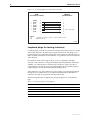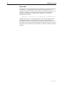
1
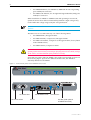
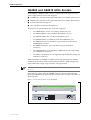
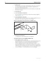
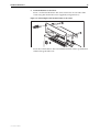
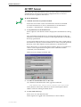
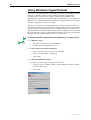
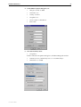
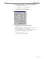
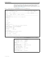
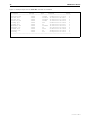
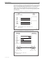
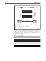
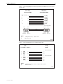
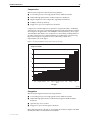
AR400 SERIES ROUTER
Hardware Reference
AR410
AR410S
AR440S
AR441S
AR450S
2
AR400 Series Router
AR400 Series Router Hardware Reference
Document Number C613-03086-00 REV A
Copyright © 2004 Allied Telesyn International, Corp.
19800 North Creek Parkway, Suite 200, Bothell, WA 98011, USA.
All rights reserved. No part of this publication may be reproduced without prior written
permission from Allied Telesyn.
Allied Telesyn International, Corp. reserves the right to make changes in specifications
and other information contained in this document without prior written notice. The
information provided herein is subject to change without notice. In no event shall Allied
Telesyn be liable for any incidental, special, indirect, or consequential damages
whatsoever, including but not limited to lost profits, arising out of or related to this
manual or the information contained herein, even if Allied Telesyn has been advised of,
known, or should have known, the possibility of such damages.
All trademarks are the property of their respective owners.
C613-03086-00 REV A
Hardware Reference
3
Contents
Contents .......................................................................................................... 3
Introduction ...................................................................................................... 4
Models Covered By This Reference .................................................................... 4
Where To Find More Information ...................................................................... 5
AR410 and AR410S Routers ............................................................................. 5
Main system ............................................................................................... 7
Environmental conditions ........................................................................... 7
LEDs and what they mean .......................................................................... 7
Power supply .............................................................................................. 8
AR440S and AR441S ADSL Routers .................................................................. 9
Main system ............................................................................................. 10
ADSL interfaces ........................................................................................ 10
Environmental conditions ......................................................................... 11
LEDs and what they mean ........................................................................ 11
Power supply ............................................................................................ 12
AR450S Router ............................................................................................... 13
Main system ............................................................................................. 13
Random Access Memory (RAM) ................................................................ 14
Encryption processor ................................................................................ 14
Environmental conditions ......................................................................... 14
LEDs and what they mean ........................................................................ 15
Power supply ............................................................................................ 15
Rack and Wall Mounting ................................................................................. 15
Online Documentation .................................................................................... 18
To access the documentation .................................................................... 18
AT-TFTP Server ................................................................................................. 19
Using Windows HyperTerminal ........................................................................ 20
Router Start-Up .............................................................................................. 23
Flash Memory ................................................................................................. 26
Testing flash memory ................................................................................ 26
RS-232 Terminal Ports (ASYN) ......................................................................... 29
Cables and Loopback Plugs ............................................................................. 30
RS-232 terminal and modem cables ......................................................... 30
Loopback plugs for testing interfaces ....................................................... 34
Test Facility ..................................................................................................... 36
Asynchronous interface tests .................................................................... 37
Ethernet interface tests ............................................................................. 37
ADSL interface tests ................................................................................. 37
WAN port tests ......................................................................................... 37
Expansion Options .......................................................................................... 38
Port Interface Cards (PICs) ........................................................................ 38
Mini Accelerator Cards (MACs) ................................................................. 38
Restricted Procedures ...................................................................................... 41
Diagnostics ............................................................................................... 41
Lithium battery replacement ..................................................................... 42
Contacting Us ................................................................................................. 42
C613-03086-00 REV A
4
AR400 Series Router
Introduction
The AR400 Series routers are high-performance broadband routers based
around 10BASE-T/100BASE-TX ports. AR410, AR410S, AR440S and AR441S
routers include a Port Interface Card (PIC) bay. The AR440S and AR441S
include an ADSL port. PIC bays add expansion flexibility by allowing the
installation of PIC cards, which are available with ISDN (PRI E1/T1, BRI S/T,
or BRI U), Ethernet, synchronous, or asynchronous ports.
The AR410 router has a dedicated Mini Accelerator Card (MAC) slot that
accommodates special purpose MAC coprocessor cards. MAC cards provide
additional functionality or performance, such as compression or encryption,
but do not add extra interfaces. All other AR400 Series routers have a built in
encryption processor.
This Hardware Reference describes the hardware features of AR400 Series
router models, including information on Mini Accelerator Cards (MACs).
Hardware and installation information for Port Interface Cards (PICs) can be
found in the Port Interface Card Quick Install Guide and Hardware Reference.
This Hardware Reference does not cover software configuration or software installation
procedures. For information on software, refer to the AR400 Series Router Software
Reference.
Models Covered By This Reference
This Hardware Reference includes information on the following models:
■
AR410
■
AR410S
■
AR440S
■
AR441S
■
AR450S
Hardware Reference updates can be found at
www.alliedtelesyn.co.nz/support/ar400/.
C613-03086-00 REV A
Hardware Reference
5
Where To Find More Information
The Documentation and Tools CD-ROM bundled with each router contains the
complete Document Set for your router and, where applicable, its expansion
options. The CD-ROM also includes tools for managing your router.
The Document Set includes:
■
The Safety Booklet for your router, which provides safety and statutory
information.
■
The Quick Install Guide for your router, which outlines how to install the
router.
■
The User Guide for your router, which describes basic configuration
procedures.
■
The AR400 Series Router Hardware Reference, which provides detailed
information on the hardware features of AR400 Series routers.
■
The AR400 Series Software Reference, which provides detailed information
on configuring the router and its software.
■
The Port Interface Card Quick Install Guide, which outlines the procedure for
installing PICs.
■
Port Interface Card Hardware Reference, which provides detailed information
on PICs.
These documents can also be downloaded from the Support Site at
www.alliedtelesyn.co.nz/support/ar400/.
AR410 and AR410S Routers
AR410 and AR410S routers consist of a base CPU card, enclosure, and power
supply. The base CPU card supports:
■
Four 10/100 Ethernet switch ports.
■
One 10/100 Eth 0 port.
■
One asynchronous RS-232 (ASYN 0) configuration port.
■
One Port Interface Card (PIC) bay.
■
One internal MAC slot (an AT-AR011V2 MAC card is factory fitted in the
AR410S router).
The PIC bay can accommodate any of the following PICs:
C613-03086-00 REV A
•
AT-AR020 PRI E1/T1 PIC, one Primary Rate E1/T1 port.
•
AT-AR021(S) BRI-S/T PIC, one Basic Rate ISDN S/T port.
•
AT-AR021(U) BRI-U PIC, one Basic Rate ISDN U port.
•
AT-AR022 ETH PIC, one Ethernet LAN AUI/10BASE-T port.
•
AT-AR023 SYN PIC, one Synchronous port with universal 50-way
AMPLIMITE connector.
•
AT-AR024 ASYN4 PIC, four Asynchronous ports with RJ-45
connectors.
6
AR400 Series Router
•
AT-AR026 4ETH PIC, four 10BASE-T/100 BASE-TX auto-negotiating
ports with RJ-45 connectors.
•
AT-AR027 VoIP-FXS PIC, two Foreign Exchange Subscriber (FXS) ports
with RJ-11 connectors.
When installed in an AR410 or AR410S router and operating in V.35 mode,
synchronous PICs have full V.35 functionality, but their output voltages may
not be within the voltage range set by the V.35 specification.
Synchronous PICs installed in an AR410 or AR410S cannot be fully tested with
Syntester.
The MAC slot can accommodate any one of the following MACs:
•
AT-AR010 EMAC, Encryption MAC.
•
AT-AR011 ECMAC, Compression/Encryption MAC
•
AT-AR011 V2 ECMAC, Compression/Encryption MAC (factory fitted
in the AR410S router).
•
AT-AR012 CMAC, Compression MAC.
MACs should be installed by authorised service personnel only. Unauthorised
opening of the router lid may cause danger of injury from electric shock, damage
to the router, and invalidation of the product warranty.
Front and rear panels of the AT-AR410 router with a PIC installed are shown in
the following figure. Apart from a different model name, the AR410S is
externally identical to the AR410.
Figure 1-1: Front and rear panels of the AT-AR410 Series router.
AR410
PIC BAY0
STATUS
Branch Office Router
10BASE-T/100BASE-TX SWITCH PORTS
FULL DUP
FULL DUP
LINK/ACT
POWER
ENABLED
SYSTEM
ETH0
LINK/ACT
100M
100M
1
2
3
4
Tx
PIC BAY0
SYN
Rx
10BASE-T/100BASE-TX SWITCH PORTS
3X
2X
1X
4
ETH0
CONSOLE RS-232
ASYN0
X PC
POWER
= HUB
AC Power Inlet
AC Power Switch
10/100 Switch Ports
ETH 0
Console Port
PIC Bay (with optional
AT-AR023 SYN PIC)
C613-03086-00 REV A
Hardware Reference
7
Main system
Main features of AT-AR410 and AT-AR410S routers are:
■
66 MHz RISC processor.
■
16 MBytes of synchronous DRAM.
■
8 MBytes of flash memory (1 MByte reserved for boot code).
■
4 x 10/100 Mbps full duplex Ethernet LAN ports.
■
1 x 10/100 Mbps full duplex Ethernet WAN port.
■
1 RS-232 asynchronous serial port (maximum speed 115200 bps).
■
1 PIC bay.
■
1 MAC slot for a MAC compression/encryption card (an AT-AR011V2
MAC card is factory fitted in the AR410S router).
■
Universal AC power supply.
The RS-232 asynchronous serial port (ASYN 0) can be used as a general
purpose port for terminals, printers or modems. The default communications
settings are:
•
9600 bps
•
8 data bits
•
1 stop bit
•
no parity
•
hardware flow control
Environmental conditions
■
Operating temperature range: 0 to 40º C (32º to 104º F)
■
Storage temperature range: -25 to 70º C (-13º to 158º F)
■
Relative humidity range - Storage: 5 to 95% non-condensing
■
Relative humidity range - Operating: 5 to 80% non-condensing
LEDs and what they mean
Functions of AR410 and AR410S LEDs are shown in the following table.
Additional LEDs may be present if a PIC is installed. Functions of PIC LEDs
are described in the Port Interface Card Hardware Reference.
Table 1-1: AR410 and AR410S LEDs
C613-03086-00 REV A
LED
State
Function
Power
Green
The router is receiving power and the power
switch is in the ON position
System
Amber
Lit briefly during router start up, or the router
is malfunctioning.
Off
Normal operation
8
AR400 Series Router
Table 1-1: AR410 and AR410S LEDs (Continued)
LED
State
Function
Enabled
Green
A PIC card is correctly installed and has been
detected by the router
Off
No card is installed
Green
The corresponding port is operating at fullduplex
Off
The corresponding port is operating at halfduplex
Green
A link has been established through the
corresponding port
Flashing
Data is being transmitted through the
corresponding port
Off
No link is present through the corresponding
port
Green
The corresponding port is operating at
100Mbps
Off
The corresponding port is operating at 10Mbps
(PIC Bay 0)
Full
Link/ACT
100M
Power supply
The routers have a universal AC input connector and a power switch on their
rear panel. The routers require a power input of 100-240 VAC and 50–60Hz.
Some interfaces that may be installed in the router are not transformer isolated.
This means they will be referenced to the frame ground of the equipment and
may be damaged if connected to an interface on another piece of equipment that
is at a different ground potential.
C613-03086-00 REV A
Hardware Reference
9
AR440S and AR441S ADSL Routers
Each AR440S or AR441S router consists of a base CPU card, enclosure, and
power supply. The base CPU card supports:
■
AR440S: One Asynchronous Digital Subscriber Line (ADSL) Annex A port.
■
AR441S: One Asynchronous Digital Subscriber Line (ADSL) Annex B port.
■
Five 10/100 LAN switch ports.
■
One asynchronous RS-232 (ASYN0) port.
The PIC bay can accommodate any of the following PICs:
•
AT-AR020 PRI E1/T1 PIC, one Primary Rate E1/T1 port.
•
AT-AR021(S) BRI-S/T PIC, one Basic Rate ISDN S/T port.
•
AT-AR021(U) BRI-U PIC, one Basic Rate ISDN U port.
•
AT-AR022 ETH PIC, one Ethernet LAN AUI/10BASE-T port.
•
AT-AR023 SYN PIC, one Synchronous port with universal 50-way
AMPLIMITE connector.
•
AT-AR024 ASYN4 PIC, four Asynchronous ports with RJ-45
connectors.
•
AT-AR026 4ETH PIC, four 10BASE-T/100 BASE-TX auto-negotiating
ports with RJ-45 connectors.
•
AT-AR027 VoIP-FXS PIC, two Foreign Exchange Subscriber (FXS) ports
with RJ-11 connectors.
When installed in an AR440S or AR441S router and operating in V.35 mode,
synchronous PICs have full V.35 functionality, but their output voltages may
not be within the voltage range set by the V.35 specification.
Synchronous PICs installed in an AR440S or AR441S cannot be fully tested with
Syntester.
Front and rear panels of the AT-AR440S router are shown in the following
figure. The AR441S front and rear panels look the same, except for the name on
the front panel.
Figure 1-2: Front and rear panels of the AT-AR440S
AR440S
ADSL Router
POWER
4
2
3
1
SYSTEM
PIC
ADSL
POWER
ON
PIC BAY
ADSL
C613-03086-00 REV A
5
ASYN0
100-240 VAC
50/60 Hz
2.1 A
OFF
10
AR400 Series Router
Main system
Main features of the AR440S and AR441S routers are:
■
300 MHz RISC processor.
■
64 MBytes of SDRAM.
■
16 MBytes of flash memory (1 MByte reserved for boot block code).
■
5 x 10/100 Mbps full duplex, Layer 2 switched Ethernet LAN ports. All
LAN ports have Auto-MDI, however if Auto-MDI is turned off, then all
ports are hardwired as MDI-X. Software can also force a port to either MDI
or MDI-X.
■
AR440S: 1 x ADSL Annex A port
AR441S: 1 x ADSL Annex B port.
■
1 x V.24 asynchronous DTE port.
■
802.1Q tagged VLAN support.
■
Universal AC power supply.
■
On-board hardware encryption processor for DES, 3DES and AES.
Some encryption options may require feature licenses.
The RS-232 asynchronous serial port (ASYN 0) has a DB9 male connector, is
wired as a DTE port and can be used as a general purpose port for terminals,
printers or modems. The default communications settings are:
•
9600 bps
•
8 data bits
•
1 stop bit
•
no parity
•
hardware flow control
ADSL interfaces
The ADSL port has an RJ11 connector, and supports Dying GASP. Speed
depends on the DSLAM to which the router is connected, and the length and
interference on the cable connecting them.
Table 1-2: Pinout of the RJ11 connectors on ADSL interfaces (pins are numbered from left
to right).
Pin
Function
1
Not connected
2
Not connected
3
ADSL+
4
ADSL-
5
Not connected
6
Not connected
C613-03086-00 REV A
Hardware Reference
11
Environmental conditions
■
Operating temperature range: 0 to 50º C (32º to 122º F)
■
Storage temperature range: -25 to 70º C (-13º to 158º F)
■
Relative humidity range - Storage: 5 to 95% non-condensing
■
Relative humidity range - Operating: 5 to 80% non-condensing
■
Operational altitude: 3,000 metres maximum (10,000 feet)
LEDs and what they mean
Functions of AR440S and AR441S LEDs are shown in the following table.
Table 1-3: AR440S and AR441S LEDs
LED
State
Function
Power
Green
The router is receiving power and the power
switch is ON.
System
Red
Lit briefly during router start up, or the
router is malfunctioning.
Red flashing
The fan has failed.
Off
Normal operation.
Green
A port interface card (PIC) is correctly
installed and has been detected by the
router.
Off
No PIC is installed, or the router has not
recognised the PIC.
Green
A 100 Mbps link has been established
through the corresponding switch port.
Green flashing
Data is being transmitted through the
corresponding switch port at 100 Mbps.
Orange
A 10 Mbps link has been established
through the corresponding switch port.
Orange flashing
Data is being transmitted through the
corresponding switch port at 10 Mbps.
Off
No link is present through the
corresponding port.
PIC
1-5
C613-03086-00 REV A
12
AR400 Series Router
Table 1-3: AR440S and AR441S LEDs (Continued)
LED
State
Function
ADSL
Green
A link has been established through the
ADSL port. It is ready to send or receive
data.
Green flashing fast
Data is being transmitted or received
through the ADSL port.
Green flashing
slow (1 sec)
The ADSL port is in Loopback mode.
Orange
The ADSL DSP is initialised and the port
handshakes (looking for tones) or is
physically disconnected.
Orange flashing
The ADSL port has found tones, and is
training to negotiate the link.
Green and orange
alternating
There is a fault in the ADSL port.
Off
The ADSL port is disabled, or the ADSL DSP
is initialising
Power supply
The routers have a universal AC input connector and a power switch on their
rear panel. The routers require a power input of 100-240 VAC and 50–60Hz.
Some interfaces that may be installed in the router are not transformer isolated.
This means they will be referenced to the frame ground of the equipment and
may be damaged if connected to an interface on another piece of equipment that
is at a different ground potential.
C613-03086-00 REV A
Hardware Reference
13
AR450S Router
Each AR450S router consists of a base CPU card, enclosure, and power supply.
The base CPU card supports:
■
Five 10/100 LAN switch ports.
■
Two 10/100 Eth ports.
■
Two asynchronous RS-232 (ASYN 0 and ASYN 1) ports.
Front and rear panels of the AT-AR450S router shown in the following figure.
Figure 1-3: Front and rear panels of the AT-AR450S router.
Main system
Main features of the AR450S router are:
C613-03086-00 REV A
■
400 MHz RISC processor.
■
64 MBytes of SDRAM, expandable to 256 MBytes.
■
16 MBytes of flash memory (1 MByte reserved for boot code).
■
5 x 10/100 Mbps full duplex, Layer 2 switched Ethernet LAN ports. All
LAN ports have Auto-MDI, however if Auto-MDI is turned off, then all
ports are hardwired as MDI-X. Software can also force a port to either MDI
or MDI-X.
■
2 x 10/100 Mbps full-duplex Ethernet WAN ports.
■
2 x V.24 asynchronous DTE ports.
■
On-board hardware encryption processor.
■
802.1Q tagged VLAN support.
■
Universal AC power supply.
14
AR400 Series Router
The RS-232 asynchronous serial ports (ASYN 0 and ASYN 1) are wired as DTE
ports and can be used as general purpose ports for terminals, printers or
modems. The default communications settings are:
•
9600 bps
•
8 data bits
•
1 stop bit
•
no parity
•
hardware flow control
Random Access Memory (RAM)
The AR450S has 64MB of SDRAM provided on a single DIMM. 128MB and
256MB ECC SDRAM are also supported. See your authorised Allied Telesyn
distributor or reseller for upgrade options. Other supplier’s DIMMs are not
approved, and therefore not supported, but may function correctly.
The amount of DRAM present in a router can be checked using the command:
show system
The DRAM and FLASH fields show the amounts of DRAM and flash memory,
respectively.
Encryption processor
Some encryption options require feature licences. The on-board encryption
processor has the following features:
•
single and triple DES, and AES symmetric encryption algorithms
•
SHA-1 and MD-5 hashing support
•
RSA and DH public key support.
Environmental conditions
■
Operating temperature range: 0 to 40º C (32º to 104º F)
■
Storage temperature range: -25 to 70º C (-13º to 158º F)
■
Relative humidity range - Storage: 5 to 95% non-condensing
■
Relative humidity range - Operating: 5 to 80% non-condensing
■
Operational altitude: 3,000 metres maximum (10,000 feet)
C613-03086-00 REV A
Hardware Reference
15
LEDs and what they mean
Table 1-4: AR450S LEDs
LED
State
Function
Power
Green
The router is receiving power and the power
switch is in the ON position
System
Amber
Lit briefly during router start up, or the router
is malfunctioning.
Amber flashing
The router fan has failed.
Off
Normal operation
Green
The corresponding port is operating at fullduplex
Off
The corresponding port is operating at halfduplex
Green
A link has been established through the
corresponding port
Flashing
Data is being transmitted through the
corresponding port
Off
No link is present through the corresponding
port
Green
The corresponding port is operating at
100Mbps
Off
The corresponding port is operating at 10Mbps
Full
Link/ACT
100M
Power supply
The router has a universal AC input connector and a power switch on its rear
panel. The router requires a power input of 100-240 VAC and 50–60Hz.
Rack and Wall Mounting
You can mount any AR400 Series router in a 19 inch rack, using a rack mount
bracket kit that may be supplied with the router or ordered in addition to the
router, depending on the model. You can mount AR440S and AR441S routers
on a firm wall.
To install the router in a rack
1.
Gather additional items you will need.
To install the router in a rack you will need a rack mount bracket kit.For
AR440S and AR441S routers the rack mount bracket kit is C814-44000-00.
Order these from your authorised Allied Telesyn distributor or reseller.)
You will also need a Phillips #1 screwdriver, and screws and cage nuts to
attach the brackets to your rack.
If you are also installing an optional Port Interface Card (PIC), you need a
PIC Quick Install Guide.
C613-03086-00 REV A
16
AR400 Series Router
2.
Check the rack.
Ensure that the rack is safely secured and that it will not tip over. Devices
in a rack should be installed starting at the bottom, with the heavier
devices near the bottom of the rack.
Ensure the rack has sufficient space for the router and its associated cables.
The router is 1U high.
3.
Unscrew the feet.
4.
Connect the handles to the brackets.
Screw the handles to the wider side of each bracket, using the supplied
screws (see Figure 1-4).
5.
Connect the brackets to the router.
Screw the brackets to the sides of the router, using the supplied screws (see
figure below). The router can be front or rear mounted.
Figure 1-4: Connecting the rack mount bracket to an AR440S router.
6.
Mount the router in the rack
Use appropriate rack mounting screws (not supplied).
To install the router on a wall (AR440S, AR441S only)
1.
Gather additional items you will need.
To install the router on a wall you will need a wall mount bracket kit (C81444001-00, ordered from your authorised Allied Telesyn distributor or
reseller), a Phillips #1 screwdriver and a Phillips #2 screwdriver.
If you are fixing the router to a solid masonry or hollow wall, you need
equipment to drill a 6 mm hole. The wall mount brackets are supplied with
screws and plugs to fasten the brackets to a masonry or plasterboard wall.
If you are fixing it to a wooden wall, the screws are self-tapping.
C613-03086-00 REV A
Hardware Reference
17
2.
Screw the brackets to the router.
Screw a wall mount bracket to the outer screw holes on each side of the
router using the shorter M3 screws supplied (see figure below).
Figure 1-5: Connecting the wall mount bracket to the router.
Screw the wall brackets to the wall with the brackets at the top and bottom
and the feet against the wall.
C613-03086-00 REV A
18
AR400 Series Router
Online Documentation
This section provides a step-by-step guide to accessing documentation on the
CD-ROM. Adobe Acrobat Reader must be installed to view the documentation.
To access the documentation
To use the CD-ROM, follow these steps
1.
Insert your router’s Documentation and Tools CD-ROM in the CD-ROM drive.
2.
If the Welcome screen does not appear.
Select "Run" from the Start Menu (Windows 95, 98, 2000 or XP).
Type d:\start.exe (where d: is the CD-ROM drive letter) and click OK.
3.
To view a document.
Click on the document title.
4.
To navigate around PDF documents.
Use the toolbar buttons, keyboard shortcuts, or commands from the
Document menu to page through the document.
Click on a bookmark, thumbnail or hypertext link to jump to a specific
section or topic.
Use the Search command to search for keywords or phrases.
For more information about using the Adobe Acrobat Reader, select
"Reader Guide" from the Help menu.
5.
To install any of the tools included on the CD-ROM.
Click on a link in the Welcome screen.
C613-03086-00 REV A
Hardware Reference
19
AT-TFTP Server
This section provides information on how to access and use AT-TFTP Server.
AT-TFTP Server can be used to transfer configuration files as well as to
download software patches and releases.
To use AT-TFTP Server
1.
If AT-TFTP Server has not yet been installed.
Install it now from the router’s Documentation and Tools CD-ROM.
To install AT-TFTP server, choose AT-TFTP Server from the Start >
Programs > Allied Telesyn > AT-TFTP Server menu.
2.
To set preferences for the AT-TFTP Server.
Select "Options" from the File menu to display the "Set Preferences" dialog
box.
The "Default file transfer directory" field specifies the directory that ATTFTP Server will read from or write to for file requests that do not include a
directory specification.
To prevent unauthorised access to private directories, enter a path name in
the "Restrict to directory" field. AT-TFTP Server will use only the specified
directory, even if file requests contain references to other directories.
Select "Read only" to prevent files being written to the PC. To use the PC to
archive router scripts created using the router's CREATE CONFIG
command, select "Read Write".
Make necessary changes and click "OK".
3.
To load a file from AT-TFTP Server to the router.
On a terminal connected to the router, type the command:
LOAD METHOD=TFTP FILE=filename SERVER=ipadd DEST=FLASH
where filename is the name of the file to download and ipadd is the IP
address of the PC running AT-TFTP Server.
4.
To save a TFTP Server log.
Select "Save As" from the File menu.
TFTP requests are logged to the AT-TFTP Server main window.
C613-03086-00 REV A
20
AR400 Series Router
Using Windows HyperTerminal
You can use a PC running terminal emulation software as the manager console,
instead of a terminal. There are many terminal emulation applications
available for PCs, but the most readily available are the Terminal and
HyperTerminal applications included in Microsoft Windows 95, 98, 2000 and
Windows XP. In standard Windows installations, HyperTerminal is located in
the Start > Programs > Accessories menu.
The key to successful use of terminal emulation software with the router is to
configure the software and router with matching communications parameters.
The following procedures describe how to configure Windows Terminal and
HyperTerminal for the default RS-232 Terminal Port settings on the router, but
the same principles apply to other terminal emulation programs. Note that the
dialog boxes may vary for different versions of Windows.
To configure Windows HyperTerminal for Windows 95, 98, 2000, and XP
1.
2.
3.
In Windows, select:
•
Programs > Accessories > HyperTerminal.
•
Double-click the Hypertrm.exe icon.
In the Connection Description dialog box:
•
Enter a name for the connection (e.g., AR440S)
•
Select an icon from the scrolling list.
•
Click “OK”.
In the Phone Number dialog box:
From the “Connect using:” drop-down list, select:
•
“Direct to Com n” Where “COM n” is the COM port on the PC used to
connect to the router.
•
Click “OK”.
C613-03086-00 REV A
Hardware Reference
21
4.
5.
In the COMn Properties dialog box, set:
•
“Bits per second” to 9600.
•
“Data bits” to 8.
•
“Parity” to None.
•
“Stop bits” to 1.
•
“Flow control” to Hardware.
•
Click “OK”.
From the File menu, select:
•
“Properties”
In the Connection Properties dialog box, click the Settings tab and set:
C613-03086-00 REV A
•
“Function, arrow, and ctrl keys act as” to “Terminal keys”
•
“Emulation” to VT100.
22
AR400 Series Router
6.
Click “ASCII Setup” to display the ASCII Setup dialog box. Uncheck:
•
“Echo typed characters locally”.
•
“Append line feeds to incoming line ends”.
Set other parameters as required.
•
7.
Click “OK” twice to close all dialog boxes.
Save the current session. From the File menu, select:
•
“Save”.
This creates a connection icon with the name you assigned in the
HyperTerminal group. To use the configuration:
•
Double-click the connection icon in the HyperTerminal group.
When the HyperTerminal window is displayed, press:
•
[Enter] a couple of times.
The router’s login prompt is displayed.
C613-03086-00 REV A
Hardware Reference
23
Router Start-Up
At start-up, the manager can choose to run either the software release stored in
the flash boot block, or the software release specified by the INSTALL
parameters previously set using the SET INSTALL command.
All code is executed out of system RAM. At power-up the boot code is loaded
from the flash boot block to RAM. The boot code checks the INSTALL
information then reloads RAM with the selected temporary, preferred, or default
install release (stored in flash) and runs this code.
The release is uncompressed as it loads to RAM. This may take 10–30 seconds.
At this point, any required patches are loaded from the flash file system. Any
patch is also uncompressed as it loads to RAM. This procedure ensures that the
code runs at maximum speed, and allows updates to be made to the code.
Updates can be downloaded over the network from a TFTP server and stored
in the flash file system until required at power-up.
To download software onto the router, see the Operation chapter in the
Software Reference.
All router software, patches, and configuration settings are stored as files in
flash memory. Typically, the following files will be present in flash:
■
The current installed software release. Additional software releases may
also be present.
■
The current installed patch, if any. Additional patches may also be present.
■
The online help file. All online help is stored in a separate text file designed
to be language independent. The online help file is loaded with a software
release.
■
The boot script boot.cfg. The boot script contains standard router
commands (executed on start-up to configure the router).
■
Additional user-defined configuration scripts containing commands to
configure the router for different functions. These scripts are created using
the built-in editor, the add script command (in the Scripting chapter,
Software Reference), or the create config command (in the Operation
chapter, Software Reference).
Configuration information is stored in flash memory as configuration scripts.
These scripts contain standard router commands. When a configuration
command is entered at the command prompt from a terminal, terminal
emulation program, or Telnet session, the command alters the dynamic
configuration only; this is not saved over a power cycle. To ensure that
configuration changes resulting from such commands are retained across a
power cycle, the dynamic configuration must be saved as a configuration
script, using the create config command.
When the router starts up following either a power cycle or an operatorinitiated reboot (using the restart reboot command in the Operation chapter,
Software Reference), the following sequence of operations is performed:
1.
Perform start-up self tests.
2.
Load the flash boot block release as the INSTALL boot into the router’s
RAM.
3.
Prompt the manager for changes to the default start-up procedure:
Force EPROM download (Y)?
The manager may press one of the keys listed in Table 1-5 on page 24 to
override the default installation procedure.
C613-03086-00 REV A
24
AR400 Series Router
4.
Check the INSTALL information to determine which release to load and
run, according to the INSTALL parameters, and the manager’s response to
the previous prompt. If none of the keys in Table 1-5 on page 24 are pressed,
the INSTALL parameters determine which release and patch are loaded and
run.
5.
Load the required release specified by the INSTALL parameters from the
flash file system as the main boot.
6.
Start the router.
7.
Execute the boot configuration script, if one has been configured. The boot
configuration script is either a configuration file set using the set config
command from the Operation chapter, or the file boot.cfg file, if there is one.)
A series of start-up messages is sent to asyn0 (the console or terminal port).
Figure 1-6: Example of start-up messages on an AR440S or AR450S.
INFO:
INFO:
PASS:
INFO:
INFO:
Force
INFO:
INFO:
INFO:
INFO:
INFO:
INFO:
Self tests beginning.
RAM test beginning.
RAM test, 65536k bytes found.
Self tests complete
Downloading router software.
EPROM download (Y) ?
Initial download successful
Initialising Flash File System.
IGMP Snooping is activated.
IGMP packet trapping is active for IGMP snooping, L3FILT is activated
Executing configuration script <flash:boot.cfg>
Router startup complete
Login:
After the self tests are complete, the manager is given the option of forcing a
mandatory boot from the flash boot block release. The following message is
displayed on the terminal connected to the console port (asyn0) and the router
pauses:
Force EPROM download (Y)?
If a key is not pressed within a few seconds, the start-up process continues and
all steps in the start-up sequence are executed. Pressing certain keys on the
terminal immediately after the “Force EPROM download” message is
displayed changes the router start-up process as described in the following
table.
Table 1-5: Router start-up sequence keystrokes.
Pressing key...
Forces the router to...
(no key pressed) After a few seconds, the router start up process continues.
[Y]
Load the release, without any patches, from ROM onto the RAM, and run
the full release.
[S]
Load and run the release and patch determined by the INSTALL
parameters from flash, ignoring any boot script or previous configuration
stored in flash memory.
[Ctrl/D]
Authorised
service engineers
only
Enter diagnostics mode.
Warning. Using this option may cause the router to cease functioning,
may invalidate the product warranty, and may be a breach of the product
licence agreement (“Diagnostics” on page -41).
C613-03086-00 REV A
Hardware Reference
25
During the start-up process the router generates four different types of
messages. All messages are preceded by one of the words INFO, PASS, FAIL,
or ERROR. The meaning of these words in the context of the messages is
shown in the following table.
Table 1-6: Router start-up message classes.
Message
Meaning
INFO
An informational message that an action has been taken by the system.
PASS
An informational message that a test has been completed successfully.
ERROR
An error message that a test has failed, but the system will continue to
operate.
FAIL
An error message that a fatal error condition has caused the system to
halt in an unrecoverable fashion.
WARNING
A serious error has occurred, which may indicate hardware failure.
Messages and their meanings are:
INFO: Self tests beginning.
The code loader tests are about to begin.
INFO: RAM test beginning.
The RAM tests are about to begin.
PASS: RAM test, 65536k bytes found.
The RAM test passed, and the indicated amount of memory was found
and will be used in the router. (The amount of memory depends on the
router model.)
ERROR: RAM test 5. Error address = 00345678.
A RAM test failed, at the given address. In the example, it was the fifth
test run. The RAM test repeats until it passes, so a number of messages
like this may appear. This fault means that the memory system is faulty.
If the fault continues, contact your distributor or reseller immediately.
INFO: Self tests complete.
The start-up tests have finished.
INFO: Downloading router software.
The process of downloading the router software from ROM is about to
begin.
ERROR: Code load retried.
FAIL: Code load failed.
The load of the code from ROM to RAM failed. The load is retried a
number of times. Each time a failure occurs the ERROR message is
displayed. If the maximum number of attempts is reached, the FAIL
message is displayed.
ERROR: Vector load retried.
FAIL: Vector load failed.
The load of the vector table from ROM to RAM failed. The load is retried
a number of times. Each time a failure occurs the ERROR message is
displayed. If the maximum number of attempts is reached, the FAIL
message is displayed. Contact your authorised Allied Telesyn
distributor or reseller.
INFO: Initial download successful.
The start-up tests and download from ROM are complete, and the
specified router software is about to be started. It takes a few seconds to
decompress the software release.
C613-03086-00 REV A
26
AR400 Series Router
FAIL: Unexpected exception. Offset = 40, Addr = 0100045e.
An unexpected exception occurred while the start-up was executing.
The vector offset and the program counter when the exception occurred
are given in the message. Contact your distributor or reseller.
INFO: Executing configuration script <script-name>
The configuration commands stored in <script-name> are being
executed. If an error is found in the script, one or more ERROR
messages will be displayed.
INFO: Router startup complete.
The start-up process is complete and the router is now operational.
INFO: Initialising Flash (This may take some time)
The flash file system was found to be corrupt. The router is now reinitialising the flash device to a "good" state. The process will take at
least 4 minutes, depending on the router.
INFO: IGMP Snooping is activated.
IGMP snooping has been enabled.
INFO: IGMP packet trapping is active for IGMP snooping, L3FILT
is activated
IGMP snooping has been enabled.
WARNING: IGMP Snooping not active, failed to enable ports.
The IGMP snooping could not be activated on the switch ports. This
may indicate a hardware failure. Contact your authorised Allied
Telesyn distributor or reseller.
Flash Memory
Flash memory is a non-volatile, reprogrammable, memory storage device for
router software releases, allowing upgrades to be remotely loaded from any
WAN or LAN port. Flash memory is also used to store other types of data such
as patches, logs and configurations.
Testing flash memory
There are several ways to check that onboard flash memory is installed and
operating correctly. First, check that the router has recognised the flash
memory by displaying system information (Figure 1-7 on page -27) with the
command:
show system
The second part of the display shows the types and sizes of memory installed
in the router. If the flash memory size is lower than expected, then the router’s
boot process has not correctly detected or recognised the flash memory’s
presence. If recognition fails, contact your authorised Allied Telesyn distributor
or reseller.
If the flash is recognised, display flash memory size, device type, and location
with the command:
show flash physical
A typical display is shown in Figure 1-8 on page -27.
Lastly, check the Flash File System (FFS) to ensure that it has successfully
formatted the flash. Use the command:
show file
C613-03086-00 REV A
Hardware Reference
27
If flash memory has been used in the past, it may already be formatted and
contain files. With erased or new flash memory that has been correctly
formatted, an 80 byte hidden system file is present. A typical display for an FFS
is shown in Figure 1-9 on page -28.
Figure 1-7: Example output from the show system command for the AT-AR450S router.
Router System Status
Time 02:25:09 Date 25-May-2004.
Board
ID Bay Board Name
Rev
Serial number
-------------------------------------------------------------------------------Base
191
AR450
M1-0
57681308
-------------------------------------------------------------------------------Memory DRAM : 65536 kB
FLASH : 16384 kB
-------------------------------------------------------------------------------SysDescription
Allied Telesyn AR450 version 2.6.1-00 20-Aug-2003
SysContact
SysLocation
SysName
SysDistName
SysUpTime
310708 ( 00:51:47
Boot Image
:
Software Version:
Release Version :
Patch Installed :
Territory
:
Help File
:
)
450_107.fbr size 874084 11-May-2004
2.6.1-00 20-Aug-2003
2.6.1-00 20-Aug-2003
NONE
usa
help.hlp
Configuration
Boot configuration file: ip.cfg (exists)
Current configuration: ip.cfg
Security Mode
: Disabled
Warning (2048284): No patches found.
Figure 1-8: Example output from the show flash physical command for an AR450S.
total size ............
available to FFS ...
available to boot ..
device type ...........
devices ...............
location ..............
programming power .....
block erase time ......
total erase blocks ....
FFS erase blocks ...
Boot erase blocks ..
erase block size ......
erase bit state .......
page buffers ..........
size of page buffer ...
C613-03086-00 REV A
16 MBytes
15 MBytes
1 MBytes
28F128
1
built in
off
1000 milliseconds
128
120
8
128 kBytes
1
1
32 bytes
28
AR400 Series Router
Figure 1-9: Example output from the show file command for an AR450S
Filename
Device
Size
Created
Locks
------------------------------------------------------------------------450-252a.hlp
flash
140586
09-May-2003 17:01:15
0
54-252.rez
flash
2316676 11-Dec-2003 08:49:27
0
54-261.rez
flash
2424476 21-Aug-2003 12:11:56
0
54252-03.paz
flash
150916
11-Dec-2003 08:55:25
0
config.gui
flash
363
04-Mar-2004 15:16:09
0
config.ins
flash
32
11-Dec-2003 14:00:07
0
d450se02.rsc
flash
2303244 11-Dec-2003 09:00:23
1
feature.lic
flash
39
25-Jun-2003 13:41:29
0
random.rnd
flash
3904
02-Mar-2004 09:14:48
0
release.lic
flash
64
28-Mar-2003 23:29:14
0
ssh.key
flash
321
02-Apr-2003 23:18:14
0
-------------------------------------------------------------------------
C613-03086-00 REV A
Hardware Reference
29
RS-232 Terminal Ports (ASYN)
Asynchronous interfaces (labelled ASYN0, ASYN1, RS-232 or CONSOLE) use
DB9 female connectors, DB9 male connectors, or RJ-45 connectors, depending
on the model (Table 1-7). Pinouts match those used for most building wiring
schemes (Table 1-8, Table 1-9, and Table 1-10 on page -30).
Table 1-7: Asynchronous interface connectors by model.
Router Model/Option
Connector
Wiring
Pinouts
AT-AR410
AT-AR410S
DB9 female
DCE
Table 1-8 on page -29
DB9 male
DTE
for use with
asynchronous
modems
Table 1-9 on page -29
RJ-45
-
Table 1-10 on page -30
AT-AR440S
AT-AR441S
AT-AR450S
AT-AR024 ASYN4 PIC
Table 1-8: Pinout of the DB9 female connectors on asynchronous interfaces (pins are
numbered from right to left to right).
Pin
Function
Signal Direction
1
Not connected
2
TXD
Output from router
3
RXD
Input to router
4
DCD
Input to router
5
GND
6
DTR
Output from router
7
CTS
Input to router
8
RTS
Output from router
9
RING
Input to router (only available on expansion card interfaces)
Table 1-9: Pinout of the DB9 male connectors on asynchronous interfaces (pins are
numbered from left to right).
C613-03086-00 REV A
Pin
Function
Signal Direction
1
DCD
Input to router
2
RXD
Input to router
3
TXD
Output from router
4
DTR
Output from router
5
GND
6
Not connected
7
RTS
Output from router
8
CTS
Input to router
9
Not connected
30
AR400 Series Router
Table 1-10: Pinout of the RJ-45 connectors on asynchronous interfaces (pins are numbered
from left to right).
Pin
Function
Signal Direction
1
RING
Input to router (only available on expansion card interfaces)
2
DCD
Input to router
3
DTR
Output from router
4
GND
5
RXD
Input to router
6
TXD
Output from router
7
CTS
Input to router
8
RTS
Output from router
Asynchronous interfaces follow the RS-232 standard. A range of speeds is
selectable using the set port command (Interfaces chapter, Software Reference).
Not all signals need to be connected. In particular, both DCD and CTS are not
required unless the interface has been specifically set up to use them. See the
Terminal Server chapter, Software Reference for more details. A typical terminal
connection requires only RXD, TXD and GND, but refer to the equipment
manual for the connected device for more specific data.
Cables and Loopback Plugs
This section describes how to make cables for connecting the router to
networks, terminals, and printers. It also describes loopback plugs, which are
required for testing most router interfaces.
RS-232 terminal and modem cables
The following table lists the wiring diagrams to follow when constructing
terminal and modem cables for various connector and port combinations for
asynchronous ports.
Table 1-11: Terminal and modem cables.
Cable
Figure
RJ-45 (router) to DB25 female (terminal) cable
Figure 1-10 on page -31
DB9 female (router/DTE) to DB9 female (PC/terminal/DTE) null modem cable
Figure 1-11 on page -31
DB9 male (router/modem/DCE) to DB9 female (PC/router/terminal/DTE) cable
Figure 1-12 on page -32
DB9 male (router/DCE) to DB9 male (modem/DCE) cable
Figure 1-13 on page -33
RJ-45 (router) to DB25 male (modem) standard modem cable
Figure 1-14 on page -33
R-J45 (router) to MiniDin (Macintosh)
Figure 1-15 on page -34
The RING input is available only on asynchronous ports on expansion cards. It
is not available on asynchronous ports on base CPU boards.
C613-03086-00 REV A
Hardware Reference
31
An alternative method, for both terminal and modem cables, is to wire an R-45
patch cord (a straight pin-to-pin cable with RJ-45 connectors on both ends) and
then use an RJ-45-to-DB25 adaptor wired internally as a crossed cable. These
adaptors are available in both DB25 female and male versions from data
cabling suppliers, and are supplied with wires terminated on the RJ-45 socket
and pins on the free ends. The pins are inserted into the appropriate positions
in the DB25 shell.
Figure 1-10: Pin wiring diagram for a standard RJ-45 terminal cable.
RJ45
(to switch or router)
←
→
←
→
(RXD)
(TXD)
(CTS)
(RTS)
→ (GND)
← (DTR)
← (DCD)
(RING)
Notes:
(1)
(2)
DB25
Female
1 Not connected
2
3
4
5
6 Not connected
7
8
20
22
5
6
7
8
4
3
2
1
→ Output from switch or router; ← Input to switch or router.
Cable version 1.0.
TERMINAL
Figure 1-11: Pin wiring diagram for a standard DB9 null modem cable.
DB9 Female
(to router/DTE)
← (DCD)
1
← (RXD)
→ (TXD)
→ (DTR)
Not Connected
(GND)
(RTS)
→ (CTS)
Not Connected
2
3
4
6
5
7
8
9
Pin 5
DB9 Female
(to PC/terminal/DTE)
4
6
3
2
1
5
8
7
9
Pin 1
Pin 5
Pin 1
Cable
Pin 9
Pin 6
DB9 Female — Pin View
Pin 9
Pin 6
DB9 Female — Pin View
Notes:
(1) → Output from router; ← Input to router.
(2) Cable version 1.0.
DB9FDB9F
C613-03086-00 REV A
32
AR400 Series Router
Figure 1-12: Pin wiring diagram for a standard DB9 male to female terminal cable.
DB9 Male
(to router/modem/DCE)
Not connected
→
←
←
→
←
→
←
Pin 1
DB9 Female
(to PC/router/terminal/DTE)
1
2
3
4
5
6
7
8
9
1
2
3
4
5
6
7
8
9
Pin 5
Pin 5
(DCD)
(RXD)
(TXD)
(DTR)
(GND)
(DSR)
(RTS)
(CTS)
(RING)
Pin 1
Cable
Pin 6
Pin 9
Pin 9
DB9 Male Pin View
Notes:
(1)
(2)
Pin 6
DB9 Female Pin View
→ Output from router; ← Input to router.
Cable version 1.0.
DB9MDB9F
While the asynchronous port on the AR410 and AR410S have a DCE female
socket, the show port command regards it as DTE. Signals displayed using this
command therefore for have a DTE perspective. The internal DTE pin roles are
listed in the following table.
Table 1-12: Internal DTE pin roles
Pin
Role
2
TXD
3
RXD
4
CD
5
GND
6
DTR
7
CTS
8
RTS
C613-03086-00 REV A
Hardware Reference
33
Figure 1-13: Pin wiring diagram for a DCE asynchronous port (DB9 female connector) to
modem cable.
DB9 Male
(to router/DCE)
Not connected
→
←
←
→
←
→
Pin 1
DB9 Male
(to modem/DCE)
1
2
3
4
5
6
7
8
9
3 (TXD)
2 (RXD)
1 (DCD)
5 (GND)
4 (DTR)
8 (CTS)
7 (RTS)
9
6 Not connected
Pin 5
Pin 1
Pin 5
Cable
Pin 6
Pin 9
DB9 Male Pin View
Notes:
(1)
(2)
Pin 9
Pin 6
DB9 Male Pin View
→ Output from router; ← Input to router
Cable version 1.0.
DB9MDB9F
Figure 1-14: Pin wiring diagram for a standard modem cable.
RJ45
(to switch or router)
→
←
→
←
(TXD)
(RXD)
(RTS)
(CTS)
← (GND)
→ (DCD)
← (DTR)
(RING)
Notes:
(1)
(2)
6
5
8
7
4
2
3
1
DB25
Male
1 Not connected
2
3
4
5
6 Not connected
7
8
20
22
→ Output from switch or router; ← Input to switch or router.
Cable version 1.0.
MODEM
C613-03086-00 REV A
34
AR400 Series Router
Figure 1-15: Pin wiring diagram for a Macintosh serial cable.
MiniDin
(to Macintosh)
RJ45
(to switch or router)
←
→
←
→
←
→
(RING)
(DCD)
(RTS)
(RXD)
(GND)
(TXD)
(CTS)
(DTR)
Notes:
(1)
(2)
1
2
8
5
4
6
7
3
1
2
3
4
5
6 Not connected
7
8
→ Output from switch or router; ← Input to switch or router.
Cable version 1.0.
MINIDIN
Loopback plugs for testing interfaces
Loopback plugs are used in conjunction with the Test Facility software (see the
Test Facility chapter) to test the router’s physical interfaces. The purpose of a
loopback plug is to connect the output pins on the interface to the input pins so
that any data transmitted over the interface is looped back and received at the
same interface.
On interfaces with control signals, these are also looped back. The data
received on the interface is compared with the data transmitted to determine
whether or not the interface is functioning correctly. In order to produce a
comprehensive test report, most tests performed by the Test Facility require a
loopback plug to be inserted in the interface being tested.
Some interfaces (e.g., the synchronous ports) require a specially built external
testing device (available from your authorised Allied Telesyn distributor or
reseller) to be used in conjunction with the Test Facility.
The following table lists loopback plug wiring diagrams for each interface
type.
Table 1-13: Loopback plug pin wiring diagrams.
Physical Interface
Loopback Method/Pin Wiring Diagram
RJ-45 asynchronous interface
Figure 1-16 on page -35
DB9 Male
Figure 1-17 on page -35
DB9 Female
Figure 1-18 on page -35
Ethernet TP interface
Figure 1-18 on page -35
C613-03086-00 REV A
Hardware Reference
35
Figure 1-16: RJ-45 loopback plug for testing asynchronous interfaces.
RJ45 Asynchronous Port Loopback Plug (RJ45 connector)
8 7 6 5 4 3 2 1
(RING)
(DCD)
(DTR)
(GND)
(RXD)
(TXD)
(CTS)
(RTS)
1
2
3
4
5
6
7
8
Router end view
of plug
RJ45LOOP
Figure 1-17: DB9 female loopback plug for testing asynchronous ports with DB9 male
connectors.
DB9 Male Asynchronous Port Loopback Plug (DB9 female connector)
1
2
3
4
5
6
7
8
9
Pin 5
Pin 9
Pin 1
Pin 6
DB9 Female — Pin View
DB9FLOOP
Figure 1-18: DB9 male loopback plug for testing asynchronous ports with DB9 female
Ethernet twisted pair (TP) loopback plug.
Twisted Pair (TP) Loopback Plug (RJ45 connector)
8 7 6 5 4 3 2 1
TX+
TXRX+
RX-
1
2
3
4
5
6
7
8
Not
connected
Not
connected
•Not
Switch or router
end view
TPLOOP
C613-03086-00 REV A
36
AR400 Series Router
Test Facility
A Test Facility designed to test the router’s physical interfaces and expansion
options is built into the router software. The Test Facility can be thought of as a
specialised interface module like PPP or Frame Relay. Although the router can
continue to operate normally during specific tests, any interfaces being tested
are dedicated to the Test Facility. For more information on the Test Facility’s
operation, see the Test Facility chapter, Software Reference.
Do not connect to the router via a port you are testing.
The routers and PICs support a wide range of interface types, including
Ethernet, asynchronous, synchronous, Basic Rate ISDN and Primary Rate
ISDN. Each interface type (except Ethernet interfaces on the AT-AR026 PIC)
can be tested independently using the Test Facility software. Most tests,
however, will also require the use of a loopback plug. For more information on
loopback plugs, see “Loopback plugs for testing interfaces” on page -34.
The Test Facility does not test AT-AR026 PICs.
The following examples show how to test specific interfaces.
To display test results, use the command:
show test
The following figure shows sample output from this command.
Figure 1-19: Example output from the show test command on an AR450S.
Board
ID Bay Board Name
Rev
Serial number
---------------------------------------------------------------------------Base
190
AR450
M1-0
57687095
Duration
Details
Interface State
Result
Type (minutes) Data( %OK ) Control
---------------------------------------------------------------------------eth0
complete
good
trans
TP
ENDEC
MAC
0
2
0
2
good(100.0)
good(100.0)
-
eth1
complete
good
trans
TP
ENDEC
MAC
0
2
0
2
good(100.0)
good(100.0)
-
port1
port2
port3
port4
port5
complete
complete
complete
complete
complete
good
good
good
good
good
-
2
2
2
2
2
good(100.0)
good(100.0)
good(100.0)
good(100.0)
good(100.0)
-
asyn0
complete
good
-
1000
good( 99.0)
good
enco0
no test
----------------------------------------------------------------------------
C613-03086-00 REV A
Hardware Reference
37
Asynchronous interface tests
Asynchronous interfaces require a loopback plug to be installed before the test
will operate. See “Cables and Loopback Plugs” on page -30 for details of how
to make a loopback plug. To start a test of an asynchronous interface, use the
command:
enable test int=asynn
where n is the interface number. This runs the test for 4 minutes. Use the show
test command (Test Facility chapter, Software Reference) to observe the test
progress.
Ethernet interface tests
The Test Facility does not test Ethernet interfaces on AT-AR026 PICs.
A loopback plug is required to run the first part of the Ethernet LAN test. See
“Cables and Loopback Plugs” on page -30 for details of how to make a
loopback plug. To start a test of an Ethernet interface, use the command:
enable test int=ethn
where n is the Ethernet interface number. This runs the test for 4 minutes. Use
the show test command (Test Facility chapter, Software Reference) to observe
the test progress.
ADSL interface tests
No loopback plug is required to test an ADSL interface. To start a test of an
asynchronous interface, use the command:
enable test int=adsln
where n is the interface number. Use the show test command (Test Facility
chapter, Software Reference) to observe the test progress.
WAN port tests
To fully test synchronous interfaces, an external tester (available from your
authorised Allied Telesyn distributor or reseller) is required. A loopback plug
is not required to test BRI interfaces.
To start a WAN interface test, use the command:
enable test int=synn
or
enable test int=brin
where n is the WAN interface number. This runs the test for 4 minutes. Use the
show test command (Test Facility chapter, Software Reference) to observe the
test progress.
If a test fails, contact your authorised Allied Telesyn distributor or reseller.
C613-03086-00 REV A
38
AR400 Series Router
Expansion Options
Some of the AR400 Series routers allow the following expansion options:
■
Port Interface Cards (PIC) - for routers with PIC bays, you can install a PIC
when you require it.
■
Mini Accelerator Cards (MACs) - for the AR410, you can order a MAC
when you purchase the device, or get one fitted later by authorised service
personnel.
Port Interface Cards (PICs)
PICs (Port Interface Cards) can be installed in all AR400 Series routers except
the AR450S. The sections describing each router model (earlier in this
Reference) list the PICs that can be installed in each model. Installation
information for PICs is in the Port Interface Card Quick Install Guide. Detailed
PIC hardware information is in the Port Interface Card Hardware Reference.
The PIC Quick Install Guides and Hardware References are included on the
Documentation and Tools CD-ROM bundled with all AR400 Series routers.
They can also be downloaded from the Support Site at
www.alliedtelesyn.co.nz/support/ar400/.
Mini Accelerator Cards (MACs)
On AR410 routers, Mini Accelerator Cards (MACs) provide additional
processing features or performance, but do not add extra physical interfaces to
the router. A MAC can be installed in the dedicated MAC slot (labelled
Coprocessor Interface) inside the AR410. An AT-AR011V2 MAC card is factory
fitted in the AR410S router.
MACs should be installed by authorised service personnel only. Unauthorised
opening of the router lid may cause danger of injury from electric shock, damage
to the router, and invalidation of the product warranty.
Three MACs are available:
■
AT-AR010 EMAC, Encryption MAC.
■
AT-AR011 V2 ECMAC, Encryption/Compression MAC.
■
AT-AR012 CMAC, Compression MAC.
How MACs work
MACs provide routers with high performance hardware-based encryption
and/or compression services. MACs have a DMA slave processor, which
operates independently of the base system. This processor is responsible for
the transfer of data between the base system and the MAC, and the control of
local high speed encryption and compression data processing devices.
This architecture allows data encoding to be performed off-line without
involving the base router processor in the process, thereby maximising MAC
performance while at the same time minimising impact on the router.
C613-03086-00 REV A
Hardware Reference
39
Compression
MAC-based compression has the following features:
■
Local 32-bit processor for high speed control and data transfer.
■
Dedicated high performance 32-bit compression hardware.
■
High compression ratio Lempel-Ziv algorithm in hardware.
■
2 MBytes of history memory.
■
Support for up to 127 compression channels.
Compression and decompression operations are performed by a 32-bit data
compression coprocessor specifically designed for high-performance LempelZiv compression applications. The 2 MBytes of history memory allows up to
127 individual data links to use compression concurrently, enabling MACs to
provide compression for complicated network architectures. The following
figure shows typical compression ratios achieved by a MAC for a
representative set of file types.
Figure 1-20: Typical hardware compression ratios by file type.
Compression Ratio
7
6
5
4
3
2
1
0
Font
Program Window
Text
Object
Spread C source
sheet
EPS
Bitmap
TIFF
File Type
CMPRATIO
Encryption
MAC-based encryption has the following features:
■
Local 32-bit processor for high speed control and data transfer.
■
Dedicated high performance 32-bit Data Encryption Standard (DES)
hardware.
■
Optional key access control.
■
Support for up to 127 encryption channels.
MAC DES encryption is based on a fast 32-bit device that complies with FIPS
PUB 46, ISO DEA-1 and ANSI X3.92 standards.
C613-03086-00 REV A
40
AR400 Series Router
Dual mode
Throughput of an encrypted link can be dramatically increased by using data
compression. To support this, ECMACs support both encryption and
compression to provide a dual mode that allows combined compression and
encryption operations. So that the compression phase will have the best
opportunity at finding non-random data, compression occurs before
encryption, in the order:
compression → encryption →//→ decryption → decompression
Adding compression to an encrypted link increases line throughput. Once
compression has been carried out there is less data requiring encryption,
passing back to the base system, and transferring across the network, so less
base system bus and network link bandwidth is required for a given amount of
data. This results in the dual operation being very effective where encryption is
required.
C613-03086-00 REV A
Hardware Reference
41
Restricted Procedures
Diagnostics
The router software includes a set of diagnostic programs. These programs
perform basic level checks of all system components. They do not run in
conjunction with the normal operating code, and require that the system be
totally dedicated to their use. A detailed knowledge of the way your router
hardware functions is necessary if diagnostics are to be used effectively.
Diagnostic mode should be used by authorised service personnel only.
Unauthorised use of diagnostic mode may cause the router to cease functioning,
may invalidate the product warranty, and may be a breach of the product
licence agreement.
To enable diagnostics mode
The router does not function as a router while diagnostic mode is running.
Diagnostics do not perform checks on AT-AR026 PICs.
1.
Connect a terminal to the console port.
Connect a terminal to the console port (port 0) on the router’s rear panel,
and set the terminal communications parameters to:
2.
•
9600bps
•
8 data bits
•
1 stop bit
•
No parity
•
Hardware flow control.
Restart the router.
Restart the router, either by switching it off and on again using the power
switch on the rear panel, or by using the terminal to login and enter the
command:
restart reboot
3.
Enable diagnostics mode during start-up.
During the router start-up process, press [Ctrl/D] on the terminal to enter
diagnostics mode when you see the following prompt:
Force EPROM download (Y)?
A banner page is displayed on the terminal (see figure below). This can be
used to check that the terminal is correctly connected.
Figure 1-21: Diagnostics banner page.
* * * Diagnostic Mode * * *
version: 1-Jul-2004
Main Menu:
0. Restart
1. Full RAM test
2. ROM checksum test
Enter selection ==>
C613-03086-00 REV A
42
AR400 Series Router
To run a diagnostic program, enter the corresponding letter or number. There
are several sub-menus to cover the different options. The following table lists
keys that control the basic operation of the diagnostics.
Table 1-14: Basic commands for running diagnostics.
Key
Function
Q
Quits any running tests and displays the banner page.
S
Prints a summary of test results so far.
Diagnostics are designed to be used with all models of the router, and therefore
some instances of particular tests are not appropriate for some models. A
reasonable level of understanding of the system structure is needed to operate
diagnostics and interpret the results. Diagnostics only require the base CPU
board to be installed in the system.
To restore the router to normal operation, perform a restart by switching its
power switch (rear panel) OFF and ON.
This hardware manual is not intended as a guide to diagnostics. Diagnostics are
designed to be run by service personnel only. For more information, contact your
authorised Allied Telesyn distributor or reseller.
Lithium battery replacement
The routers have a replaceable lithium battery. If replacing the battery, use a 3V
lithium button cell, type CR2032 or equivalent.
The battery should be replaced when the router:
•
has been in storage for more than two years
•
has only been powered up intermittently over a two year period
•
loses its time setting
Batteries should be replaced by authorised service personnel only.
Unauthorised opening of the router lid may cause danger of injury from electric
shock, damage to the router, and invalidation of the product warranty.
Contacting Us
With locations covering markets in North America, Latin America, and
Europe, Allied Telesyn provides local sales and technical support worldwide.
To find the representative nearest you, visit Allied Telesyn on the Internet at
www.alliedtelesyn.com .
C613-03086-00 REV A