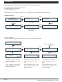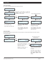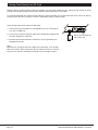
1
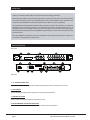
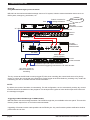
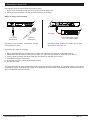
MR 1300
MESSAGE RECORDER / PLAYER
MSG 2
MR 1300
amperes
INSTRUCTION MANUAL
VER.1 / JAN 2012
Introduction
Thank you for trusting another product from Amperes, a brand of emerging preference.
MR1300 has been added to the list of product range after much researches were done on the needs and wishes
of the users throughout the years. We had added enough functions and flexibilities over the operations for the
requirement of PA installations and this product shall be able to cater for any size of installations.
Among distinctive features available in MR1300 shall the storage of voice file in SD card which can support to 2
GB capacity, which is more than enough for most operations, front and rear message triggering of up to 16
messages and choice of recordings, via the front jack for microphones as well as rear line input RCA jacks.
MR1300 shall not be a static product, but upgradable through bootloader for newer version of firmware that may
be issued in future.
We trust that MR1300 shall perform beyond your expectations and it shall be the right choice to install one in
your system, working tirelessly for years to come.
Parts Identification
Front View
1
6
MR 1300
3
2
4
11
18
15
13
DC 24V
+
5
7
9
10
14
12
Rear View
1
1. 1/4” STEREO PHONE JACK
Stereo phone jack for microphone inputs with balanced input signal. Used for recording voice to the unit.
2. LCD DISPLAY
2 X 18 character LCD displaying units parameters and programming instructions.
3. CONTROL BUTTONS
Buttons for Menu and various playback and recording controls
4. FRONT MESSAGE ACTIVATION SHORT KEY
8 front short key for direct message activation ; MES 1 to MES 8 with LED indicators.
page 2
MR1300 MESSAGE RECORDER / PLAYER
Parts Identifications ( continued )
5. POWER CONNECTORS
24V DC input for power, use only regulated power supply or Amperes PS9400 power supply unit.
6. POWER SWITCH
Power switch for the unit.
7. RESET BUTTON
Button for resetting the unit to factory default. Use only when required as settings done previously would be lost.
Voice files stored in the SD card shall not be affected.
8. RS485 DATA CONNECTIONS
RS485 data port for external controls and monitoring.
9. RS232 DATA PORT
RS232 data port for interfacing to PC for firmward upgrades.
10. SD CARD
SD card slot, up to 2 GB capacity is supported by the unit ( Shall be upgraded in future )
11. LINE INPUTS
RCA jack for recording from external source with line output, such as CD, MP3 players, etc
12. LINE OUTPUTS
Unbalanced line output for message playback.
13. EXTERNAL TRIGGER PORT
Dry contacts to trigger the stored messages 1 to 16. Only voltage free contact is allowed to avoid damage.
14. DRY CONTACT
Dry contact is available whenever a message is activated. Can be used to interface with other devices such as
volume controllers, zone selectors, etc.
15. XLR BALANCED OUTPUT
Balanced line output with XLR female connector.
www.ampereselectronics.com
page 3
Schematic Diagram
External Contacts for Message
Triggering ( Up to 16 contacts )
MR1300 MESSAGE
RECORDER / PLAYER
MSG 2
MR 1300
a m pe re s
Alternative Bypass :
Audio and Trigger
direct to EP1200
Balanced Audio
( input 1 / 2 / line in )
CH1
CH2
CH3
CH4
CH5
CH6
MX2222
SO URCE
E X T IN P U T
TON E CTRL
OFF
M ASTER
MX 2222
Note :
With direct
connection to
EP1200, message
shall bypass
audio signal from
MX2222 with
higher priority
SELECT
TUNER
OFF
M IN
M IN
MAX
M IN
S IG IN
MAX
S IG IN
M IN
MAX
S IG IN
M IN
MAX
S IG IN
M IN
MAX
S IG IN
M IN
S IG IN
MAX
M IN
S IG IN
MAX
M AX
C H IM E
M IN
PO W ER
CASS
CD
a m pe re s
AUX
M AX
M IX E R
T R E B LE
BASS
M IN
S IG IN
MAX
M U S IC S O U R C E
Bal. Audio
to Pre-Amp input
M IC
TEST
FIR E
S IR E N A C T IV A T E
E P 1200
EP1200
POW ER
Amp input
a m pe re s
AMPLIFIERS
PA 2120
120 Watts
PO W ER
POW ER
PA 2120
PROTECT
I
C L IP
O
a m pe re s
S IG N A L -10 dB
S IG N A L -40 dB
100V Output
24V Override Trigger
to ALL CALL Conn.
ZS5121
O V E R R ID E
a m pe re s
O V E R R ID E
2 x 100V Audio
2 x 24V Override
VC VOLUME
CONTROLLERS
SPEAKERS
page 4
MR1300 MESSAGE RECORDER / PLAYER
Connecting the Unit
MR1300 can be used as :
- source playback unit, for delivering pre-recorded messages or songs, and if repetitive playback at certain times is required,
it can be used together with a timer.
- Emergency broadcast message playback unit, which is linked to external triggering devices or systems, such as alarm, BAS
or emergency push button.
Connections of both applications are shown in the diagrams below.
Option A :
Using MR1300 for Normal Message Source
See Note Below
UNBALANCE
LINE OUT
COM
COM
COM
CH8
NO
COM
CH7
NO
CH6
NO
CH5
NO
CH4
COM
COM
CH3
COM
CH2
NO
COM
CH1
NO
+
NO
DC 24V
NO
PT 1800
com to ground
Quality Product From
OUTPUT
LEVEL
AMPERES ELECTRONICS
PT1800
PROG.TIMER
RELAY DRY CONTACT
MR 1300
Dry contact connection to
trigger message
MR1300
MESSAGE
RECORDER / PLAYER
DC 24V
+
Balanced audio output
MX2222
Another Quality Product From
DC INPUT
24V DC
CASS
TUNER
AUX
CD
EXT IN
OUTPUT
REC
BGM
CHIME
MIXER
MIN
MAINS : 230V +/-10%
AC 50 / 60HZ
LINE OUT
MAX
CH.1 / 2 / EXT.IN
PRIORITY MUTE
CH6
CH5
CH4
CH3
CH2
CH1
MX2222
MIXER
Balanced audio output
Another Quality Product From
EP1200
S/N :
MESSAGE IN
REMOTE TRIGGER
MESSAGE
SIREN
PRE IN
PRE OUT
INPUT LEVEL
MESSAGE
MIN
SIREN
MAX MIN
EP1200
EMERGENCY
PAGING PANEL
MAX
Audio output to Power
Amplifiers, etc
Stored messages can be played either from the front buttons or via the remote triggering ports.
The above diagram shows connections of 3 output channels of PT1800 connected to 3 individual triggering ports of
MR1300. It is intended to perform 3 different times to playback 3 different messages. Activation of each message is
via negative grounding.
Output from MR1300 can be unbalanced using RCA jack, or balanced signal using XLR jack. Both outputs are in mono
mode, with line level signal.
NOTE :
Activation of a stored message shall can be either momentarily or pulse contact to ground. To activate from PT1800
timer, we recommend that the contact option at the channel output to be set to Pulse.
www.ampereselectronics.com
page 5
Connecting the Unit
Option B :
Using MR1300 for Emergency Announcement
MR1300 can be used as essential message source to PA system, linked to external activation device such as
BAS system, emergency push button, etc.
MR 1300
See Note Below
Switch or sensor for
message activation
Gnd
MR1300
MESSAGE
RECORDER / PLAYER
DC 24V
+
2C cable
Bal.audio out
MX2222
Another Quality Product From
DC INPUT
24V DC
CASS
TUNER
AUX
CD
BGM
CHIME
MIXER
MIN
MAINS : 230V +/-10%
AC 50 / 60HZ
MX2222
MIXER
EXT IN
OUTPUT
REC
LINE OUT
MAX
CH.1 / 2 / EXT.IN
PRIORITY MUTE
CH6
CH5
CH4
CH3
CH2
CH1
Bal.audio out
Another Quality Product From
EP1200
S/N :
MESSAGE IN
REMOTE TRIGGER
MESSAGE
SIREN
PRE IN
PRE OUT
INPUT LEVEL
MESSAGE
MIN
SIREN
MAX MIN
EP1200
EMERGENCY
PAGING PANEL
MAX
2C cable
Audio output to
power amplifier
COM
COM
COM
100V
COM
100V
COM
100V
COM
AMP11 ZON11 AMP12 ZON12
100V
AMP10 ZON10
100V
COM
COM
ZON9
100V
COM
AMP 9
100V
COM
ZON8
100V
AMP 8
100V
COM
COM
ZON7
100V
AMP 7
100V
REMOTE SELECT
100V
ZON6
COM
COM
COM
AMP 6
100V
ZON5
100V
COM
COM
AMP 5
100V
COM
ZON4
100V
AMP 4
100V
COM
ZON3
COM
AMP 3
100V
COM
ZON2
100V
AMP 2
100V
COM
ZON1
COM
AMP 1
100V
REMOTE SELECT
COM
RLY ZS
CON PR
100V
RLY
TRIG
100V
+
100V
ZS 5121
DC 24V
ZS5121
ZONE SELECTOR
Amplifiers input and output connections
Zone selector triggering connectors to TD zone decoder
24V relay contact to
volume controllers for
overriding
The dry contact at the MR1300 is used to trigger EP1200, thus overriding the normal audio source for priority
paging. It is then also connected to the Emergency Relay trigger at the Zone Selector, providing a dry contact for
connecting 24V DC to override external volume controllers
NOTE :
By default, the mode of activation is momentarily. For this configuration, set it to momentarily, and the dry contact
shall be closed for the duration of the playback. This shall perform bypass of mixer audio output at EP1200 until
the message is stopped.
Triggering Pre Recorded Message via UART ( RS485 )
MR1300 allows remote message activation via RS485 throught the port available at the rear panel. This use this
feature, please enquire from us for further technical details.
Upgrading of firmware is also made possible via the RS232 port. Any new firmware updates notification shall be
posted from time to time.
page 6
MR1300 MESSAGE RECORDER / PLAYER
Connecting the Unit
Option C :
Using BAS to control MR1300
In cases where Building Control System or BAS to be the domain controller including emergency voice annoucement,
it can be used to activate particular pre-recorded messages at MR1300.
The BAS would provide a close dry contact, which would activate mixer audio bypass at EP1200, as well as triggering
a message at MR1300.
MR 1300
The typical connection diagram is illustrated below :
MR1300
MESSAGE
RECORDER / PLAYER
DC 24V
+
2C cable
Bal.audio out
DC INPUT
24V DC
MX2222
Another Quality Product From
REC
CASS
TUNER
AUX
CD
EXT IN
OUTPUT
BGM
CHIME
MX2222
MIXER
MIXER
MIN
MAINS : 230V +/-10%
AC 50 / 60HZ
LINE OUT
MAX
CH.1 / 2 / EXT.IN
PRIORITY MUTE
CH6
CH5
CH4
CH3
CH2
CH1
Bal.audio out
Another Quality Product From
EP1200
EMERGENCY
PAGING PANEL
EP1200
S/N :
MESSAGE IN
REMOTE TRIGGER
MESSAGE
SIREN
MESSAGE
SIREN
MAX MIN
MAX
2C cable
COM
COM
100V
COM
COM
100V
COM
100V
COM
AMP11 ZON11 AMP12 ZON12
100V
COM
100V
AMP10 ZON10
100V
ZON9
100V
COM
AMP 9
COM
COM
ZON8
100V
AMP 8
100V
COM
COM
ZON7
100V
AMP 7
100V
REMOTE SELECT
100V
ZON6
COM
COM
COM
AMP 6
100V
COM
ZON5
100V
COM
AMP 5
100V
COM
ZON4
100V
COM
COM
AMP 4
100V
ZON3
100V
AMP 3
100V
ZON2
100V
COM
AMP 2
COM
ZON1
COM
AMP 1
100V
REMOTE SELECT
COM
RLY ZS
100V
RLY
TRIG CON PR
Audio output to
power amplifier
100V
+
100V
ZS 5121
DC 24V
PRE OUT
INPUT LEVEL
MIN
BAS System
providing a
voltage free
PRE IN
ZS5121
ZONE SELECTOR
Amplifiers input and output connections
Zone selector triggering connectors to TD zone decoder
24V relay contact to
volume controllers for
overriding
As EP1200 requires a latched contact to bypass the mixer output audio, BAS system should be able to provide a
latched contact for the duration of the event.
Example, a fire sensor is activated and the BAS pick up the distress signal, it then provides a close contact, which
is then required to mute normal BGM through EP1200. In the same time, activate a warning message via MR1300.
The message shall be repeated until inspection is done and distress status is removed.
www.ampereselectronics.com
page 7
Setup Menu
Few simple setting should be done to the unit before operating. Among them,
1. Activation mode ( momentary or latched )
2. Audio level and tone controls
3. Message designations
The setting up can be performed via the menu, or through PC ( software shall be available soon ).
The Menu Flowchart :
MR1300
MSG Rec / Player
Menu /
Enter 1. AUDIO
Openning display
Next
2. MESSAGE
Setting output volume, bass
and treble
Next
Next
5. SAVE & EXIT
Message playback setting
Next
Next
4. SYSTEM
3. RECORD
System update and
bootloading
To exit the system menu
To record and save messages
1. Audio Sub Menu
It is used to set the output volume, bass and treble of pre-recorded messages.
1. AUDIO
Exit to Audio Sub Menu
Menu / Enter
EXIT
Next
Next
1.2 BASS
1.1. VOLUME
Menu / Enter
1.3. TREBLE
Menu / Enter
Menu / Enter
2
1.1. VOLUME
*
Max
1.2. BASS
*
0
1.3. TREBLE
*
0
Use Next or Prev button to
select the volume level ; from
Mute to 8 and Max.
Use Next or Prev button to
select the bass level ; from 0
to 6
Use Next or Prev button to
select the treble level ; from 0
to 6
Once selected, press Enter
and the display shall return to
Volume sub menu.
Once selected, press Enter
and the display shall return to
Bass sub menu.
Once selected, press Enter
and the display shall return to
Treble sub menu.
page 8
MR1300 MESSAGE RECORDER / PLAYER
Setup Menu
2. Message Sub Menu
Pre-recorded message setting is done using this sub menu.
2. MESSAGE
Menu / Enter
2. M01
102 KB
Use Next or Prev button to select the
Message number. 102 KB indicates the
message’s memory space
Exit to Message Sub Menu
Menu / Enter
EXIT
Next
2.1. PLAY
102 KB
Next
2.2. REPEAT
Menu / Enter
2.3. CLEAR
102 KB
Menu / Enter
Menu / Enter
2
2.1. PLAY
102 KB
>
2.2. REPEAT
*
The pre-recorded message
nbr 1 selected to play.
2.3. CLEAR
*
2
NO
Use Next or Prev button to
select the repeat number,
from 1 to 3.
Use Next or Prev button to
select either to delete or
keeping the message.
Once selected, press Enter
and the display shall return to
2.2 Sub Menu.
Once selected, press Enter
and the display shall return to
Clear sub menu.
Exit to return to the sub menu
3. Record Sub Menu
This sub menu is used to record voice via the front microphone or through rear RCA jack. Also refer to section
“Recording Message”.
3. RECORD
Recording begins with
duration shown.
Menu / Enter
3.1. REC
Enter
3.1. REC
Enter
START
3.1. REC
00 : 07
STOP
Menu / Enter
Once message designation is
determined, press Enter to
return to sub menu 3.1.
Repeat the above flow to
record another message.
Enter
2
3.1. REC SAVE
12.7 MB
M01
Press Enter to stop recording,
and the recording file size will
be shown.
Use Next / Prev button to
select the message designation, which is shown on the
right bottom corner of the
display
www.ampereselectronics.com
page 9
Connecting the Unit
4. System
This menu is used to check the firmware version and bootloading for firmware upgrade.
Note : Firmware upgrade featur would be available in future.
4. SYSTEM
Menu / Enter
4.1. SYSTEM INFO
V01.11
Next
Next
Next
4.2. UPDATE
4.4. FACTORY RESET
4.3. CLEAR MESSAGE
Menu / Enter
Menu / Enter
Menu / Enter
2
2
4.3. CLEAR MESSAGE
*
Yes
4.4. FACTORY RESET
*
Yes
Use Next or Prev button to
select Yes or No.
Use Next or Prev button to
select Yes or No.
Use Next or Prev button to
select Yes or No.
Details on upgrade to be
available in near future.
Press Menu to return to Sub
Menu 4.3
Press Menu to return to Sub
Menu 4.3
4.2. UPDATE
* v01.11
Yes
5. Save and Exit
Enter this sub menu to return to operting mode.
5. SAVE & EXIT ?
NO
Use Next or Prev button to
select Yes or No.
Yes is to save any changes
made and return to operating
mode.
page 10
MR1300 MESSAGE RECORDER / PLAYER
Recording a Voice File
Recording a voice file can be done in two ways, being
1. Direct voice recording microphone / line input from music player and
2. Saving a voice file directly into SD card and rename it accordingly.
Option A : Direct voice recording
MR 1300
CD 1001
I
O
RCA jack
1/4” stereo
phone jack
Dynamic
microphone
Recording using dynamic microphone through
front panel phone jack.
Line output audio source :
CD / PC Output / MP3
Recording using external line audio source with
RCA jack at rear of the unit
To perform this option of recording,
1.
2.
3.
4.
5.
6.
Select the approriate type of audio source ; either using dynamic microphone or line audio source
Select Menu 3.0 Record and select the sub menu 3.1 ( Also see the section of Setup the Unit - Menu )
Press to Start recording and talk through the microphone or start the music source
Press Enter to stop the recording
In the next sub menu, select the Message number.
Exit the sub menu.
The direct recording of voice shall be saved into the SD card through PCM coding. The quality is best for voice and it
is suitable for music. To obtain a high quality music playback, we recommend using the Option B of saving file method,
which is explained in the next section.
www.ampereselectronics.com
page 11
Saving Files Directly Into SD Card
MR1300 allows various format of files for playback, such as MP3, WMA and etc. Saving a high quality of audio
format, such as MP3 would produce better sound output,especially for music files.
As currently MR1300 only peform PCM coding for direct recording, we recommend that music file to be directly
stored into the SD card, in order to obtain a reasonable quality of audio output.
A few simple steps to save files into SD Card :
1. Insert a SD card provided into Card Reader which is connected to
your PC via USB port.
2. From source window, drag the audio file to destination window with
SD card. Repeat for other files
Slot for SD Card at the
rear of the unit
3. Rename the transferred files to enable it to be recognised by the
Message Recorder.
Note :
MR1300 only recognise the first 3 digits of the file name, such as M01,
M02 and so forth. Other extensions can be used as reference. Thereby
any file name must be renamed according to the message location.
page 12
MR1300 MESSAGE RECORDER / PLAYER
Message Playback
Stored voice file can be played by using the front direct switches ( Message 1 to 8 ) or via the remote triggering
ports ( Message 1 to 16 ).
MSG 2
Front switch activation
2
1
To start a playback via the front panel switches,
1. Select the Message Number ( MSG01 to MSG08 )
2. Press the
button and the selected will play, with LCD indicates the time running and LED blinking.
To stop playback, press the Stop
button.
The rear and front activation for MSG01 to MSG08 are paralled. Currently there are no priority of which message is
activated, with first come first go basis.
BAS
TIMER
E/M
GND
Rear port activations
Activation via rear port can be from any external device or system providing a voltage free contact.
To activate a message, the relevant port shall be grounded and the type of activation can be either pulse contact or
latch.
For pulse contact ( momentarily ), a close circuit will activate the message, and while the message is being played,
another incoming pulse shall deactivate the announcement.
In cases where a latched contact is provided, the message will be played for as long as the closed contact remained
as such.
www.ampereselectronics.com
page 13
Communication Ports
The communication ports available are RS232 and RS485.
RS232 is used for communication with PC for bootloading / firmware upgrades while RS485 shall be used to communicate with other devices within the system.
Further information on this section shall be available soon.
page 14
MR1300 MESSAGE RECORDER / PLAYER
Summary of Features
2 GB SD card ( Supplied )
8 front direct message playback buttons and 16 remote triggering
MP3 quality of playback with balanced audio output ( with MP3 recorded files )
Recording via dynamic microphone or line audio input
Message assignment to front key or remote triggering port
Playback controls mode ie. Repetitive or Play Once and manual
Audio output setup ie. volume, treble and bass for message playback
Dry contact port upon message triggering for interfacing to other devices
Technical Specifications
Operating voltage
24V DC
Power consumption
1.2W
Operating temperature
0 to 40 deg
Data communication
RS485 at 19.2 kbps
Remote triggering
16 ports via dry contact
Front triggering
8 direct message playback key
Indicators
LED at switches, LCD display
Inputs
Line input; unbalanced via RCA jack
Microphone input; via front phone jack
Input sensitivity
Line (1.2V, 10 K Ohm)
Microphone :(0.775V 600 Ohm)
Input frequency response
Line : 80 - 19 KHz
Mic : 180 - 10 KHz
Audio recording sampling rate
PCM : 64 kbps
Audio recording
Line : via RCA jack
Mic recording : via front balance mic input
Playback format
PCM, MP3, WMA, etc
Memory
SD Card (Supplied with 2 GB, expandable)
Audio output
RCA unbalanced output; 1.2V
XLR balanced; line 1.2V
Playback controls
Output level, Playback, Repeat, Stop, Record
S/ N ratio
80 dB
THD + N
0.1 %
Weight (kg)
2.6 kg
Dimension (W x H x D) mm
482 x 44 x 180 mm
Due to continuous product improvement efforts, amperes electronics
reserves the rights to change the above specifications without prior notice.
Periodical updates shall be posted on website.
www.ampereselectronics.com
page 15
warranty conditions
Only Amperes Electronics Service Centres are allowed to make warranty repairs : a list of Amperes Electronics
Service Centres may be asked for by the purchaser or send directly to Amperes Electronics Sdn Bhd at 70 Jalan
Industri PBP 3, Tmn Perindustrian Pusat Bandar Puchong, 47100, Puchong, Selangor, Malaysia or its authorized
master distributor, Amperes Global Marketing. This warranty is not valid if repairs are performed by unauthorized
personnel or service centres.
This warranty covers only repairs and replacement of defective parts ; cost and risks of transportation as well as
removal and installation of the product from the main system are for the account of the purchaser. This warranty
shall not extend to the replacement of the unit.
This warranty does not cover damages caused by misuse, neglect, accident of the product as well as using the
product with power supply voltage other than shown on the product, or any other power supply source / adaptor
not recommended by the manufacturer.
This warranty does not cover damages caused by fire, earthquakes, floods. lightning and every cause not
directly related to the unit.
This warranty does not include any indemnity in favor of the purchaser or the dealer for the period out of use of
the unit; moreover the warranty does not cover any damages which may be caused to people and things when
using the product.
This warranty certificate is valid only for the described product, and is not valid if modifications are made on this
certificate or on the identification label applied on the product.
This warranty covers all the material and manufacturing defects and is valid for a period of 12 months from the
date of purchase or for a longer period in countries where this is stated by a national law. In this case, the
extension is valid only in the country where the product is purchased.
Amperes Electronics Sdn Bhd is not obliged to modify previously manufactured products under warranty if the
design changes or improvements are made.
disclaimer
Information contained in this manual is subject to change without prior notice and does not represent a
commitment on the part of the vendor. AMPERES ELECTRONICS SDN BHD shall not be liable for any loss or
damages whatsoever arising from the use of information or any error contained in this manual.
It is recommended that all services and repairs on this product be carried out by AMPERES ELECTRONICS
SDN BHD or its authorized service agents.
AMPERES series must only be used for the purpose they were intended by the manufacturer and in conjunction
with this operating manual.
AMPERES ELECTRONICS SDN BHD cannot accept any liability whatsoever for any loss or damages caused by
service, maintenance or repair by unauthorized personnel, or by use other than that intended by the
manufacturer.
amperes
PAGE 12
By :
AMPERES ELECTRONICS
www.ampereselectronics.com
Made In Malaysia
Feb 2012