1
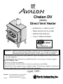
Chelan DV
(700 DV)
Direct Vent Heater
¥ HORIZONTAL or VERTICAL VENT
¥ FREESTANDING STOVE or INSERT
¥ MOBILE HOME APPROVED
¥ CLASS A CHIMNEY RETROFIT
Listed
ANSI Z21.44, Z21.11.4
CAN/CGA 1-2.19-M81, IR41, IR55, 2.17-M91
WARNING: Improper installation, adjustment, alteration, service or maintenance can cause
injury or property damage. Refer to this manual. For assistance or additional
information consult a qualified installer, service agency, or the gas supplier.
- Do not store or use gasoline or other flammable vapors and liquids in the vicinity of this or
any other appliance.
- Installation must be performed by a qualified installer, service agency or the gas supplier
IF YOU SMELL GAS
¥ Do not try to light any appliance.
¥ Do not touch any electrical switch; do not use any phone in your building.
¥ Immediately call gas supplier from a neighbor's phone. Follow the gas supplier's instructions.
¥ If you cannot reach your gas supplier, call the fire department.
- April, 1999 Installer: After installation give this manual
to the homeowner and explain
operation of this heater.
$10.00
93508079
10850 117th Place N.E. Kirkland, WA 98033
PAGE 2
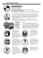
SAFETY PRECAUTIONS
¥ IF YOU SMELL GAS:
* Do not light any appliance
* Extinguish any open flame
* Do not touch any electrical switch or plug or unplug anything
* Open windows and vacate building
* Call gas supplier from neighbor's house, if not reached, call fire department
¥
¥
This unit must be installed by a qualified installer to prevent the possibility of
an explosion. Your dealer will know the requirements in your area and can
inform you of those people considered qualified. The room heater should be
inspected before use and at least annually by a qualified service person. More
frequent cleaning may be required due to excessive lint from carpeting,
bedding material, etc.
The instructions in this manual must be strictly adhered to. Do not use
makeshift methods or compromise in the installation. Improper installation
will void the warranty and safety listing.
THIS CONTROL
HAS BEEN
¥
CONVERTED FOR
NATURAL GAS
THIS CONTROL
HAS BEEN
CONVERTED TO
LP
¥
Ok
¥
¥
Gas
¥
Contact your local
building officials to
obtain a permit and
information on any
installation restrictions or
inspection requirements in
your area. Notify your
insurance company of this
heater as well.
It is imperative that
control compartments,
screens, or circulating air
passageways of the heater
be kept clean and free of
obstructions. These areas
provide the air necessary
for safe operation.
Do not store or use
gasoline or other
flammable liquids in the
vicinity of this heater.
Keep all furniture or other
combustible items at least
36" away from the front
of the heater.
This heater is either approved for natural gas
(NG) or propane (LP). Burning the incorrect
fuel will void the warranty and safety listing and
may cause an extreme safety hazard. Check the
label above the gas control valve to make sure it
matches the fuel being used. Direct questions
about the type of fuel used to your dealer.
¥
If the flame becomes
sooty, dark orange in
color, or extremely tall,
do not operate the heater.
Call your dealer and
arrange for proper
servicing.
¥
Do not operate the heater
if it is not operating
properly in any fashion or
if you are uncertain. Call
your dealer for a full
explanation of your heater
and what to expect.
¥
Do not operate if any
portion of the heater was
submerged in water or if
any corrosion occurs.
?
A
AAAA
AAAA
A
AAAA
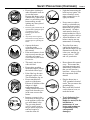
SAFETY PRECAUTIONS (CONTINUED)
¥
¥
¥
¥
¥
A
A
¥
¥
¥
¥
¥
AA
AA
AA
AA
A
Do not place clothing or
other flammable items on
or near the heater.
Because this heater can be
controlled by a thermostat
there is a possibility of the
heater turning on and
igniting any items placed
on or near it.
The door (glass) should only be
opened while lighting the pilot
or conducting service.
Damaged glass must be
replaced.
Any safety screen or guard
removed for servicing must be
replaced prior to operating the
heater.
Operate the heater
according to the
instructions included in
this manual.
If the main burners do not
start correctly turn the gas
off at the gas control
valve and call your dealer
for service.
This unit is not for use
with solid fuel
Do not place anything
inside the firebox (except
the included fiber logs).
If the fiber logs become
damaged, replace with
Travis Industries log set.
Do not touch the hot
surfaces of the heater.
Educate all children of the
danger of a hightemperature heater.
Young children should be
supervised when they are
in the same room as the
heater.
Instruct everyone in the
house how to shut gas off
to the appliance and at the
gas main shutoff valve.
The gas main shutoff
valve is usually next to
the gas meter or propane
tank and requires a
wrench to shut off.
PAGE 3
¥
Light the heater using the
built-in piezo igniter. Do
not use matches or any
other external device to
light your heater.
¥
Never remove, replace,
modify or substitute any
part of the heater unless
instructions are given in
this manual. All other
work must be done by a
trained technician. Don't
modify or replace orifices.
Allow the heater to cool
before carrying out any
maintenance or cleaning.
¥
¥
The pilot flame must
contact the thermopile
and thermocouple (see the
illustration to the left). If
it does not, turn the gas
control valve to "OFF"
and call your dealer.
¥
Do not throw this manual
away. This manual has
important operating and
maintenance instructions
that you will need at a
later time. Always follow
the instructions in this
manual.
¥
Plug the heater into a
120V grounded electrical
outlet. Do not remove the
grounding plug.
Don't route the electrical
cord in front of, over, or
under the heater
This
Manual
¥
¥
Travis Industries, Inc.
grants no warranty,
implied or stated, for the
installation or
maintenance of your
heater, and assumes no
responsibility of any
consequential
damage(s).
PAGE 4
TABLE OF CONTENTS
Introduction & Important Info. ................... 1
Finalizing the Installation
1 Door Removal ............................................. 20
2 Log, Twig, and Ember Installation .............. 20
3 Replace the Door ....................................... 21
4 Leak Test the Gas Line.............................. 21
5 Pilot Flame Inspection ................................ 21
6 Air Shutter Adjustment ............................... 21
7 Flame Inspection ........................................ 21
8 Explain Heater Operation to Owner ........... 21
Safety Precautions ............................................ 2
Features & Specifications............................ 5
Installation Options ......................................... 5
Heating Specifications ..................................... 5
Dimensions ..................................................... 5
Fuel, Emissions, Electrical .............................. 5
Stove Installation
Operating Your Heater
Installation Preparation .................................. 6
Items Required for Installation ....................... 6
Items Packed with the Chelan DV (700 DV).. 6
Order of Installation ....................................... 6
Stove Clearances .......................................... 6
Stove Placement Requirements .................... 7
Floor Protection Requirements ...................... 7
Gas Line Installation ...................................... 7
Vent Requirements ........................................ 8
Approved Vent Configurations ....................... 9
Restrictor Position................................... 9
Elbows .................................................... 9
Measuring Vent Lengths......................... 9
Approved Vent Config's with No Elbows
or Two 45° Offsets (Vertical Term.)........ 10
Approved Vent Config's with a
Horizontal Termination ........................... 11
Approved Vent Config's with a Vertical
Termination and Two 90° Elbows........... 12
Horizontal Vent Termination Requirements ... 13
Vertical Vent Termination Requirements ....... 13
Electrical Connection ..................................... 13
Before You Begin.......................................... 22
Location of Controls ....................................... 22
Starting The Pilot Flame ............................... 23
Starting the Heater for the First Time ............ 24
Turning the Heater On and Off ..................... 24
Adjusting the Flame Height ............................ 24
Adjusting the Blower Speed.......................... 25
Normal Operating Sounds ............................. 25
Maintaining Your Heater
Maintaining Your Stove's Appearance........... 34
Cleaning Your Heater ................................... 34
Yearly Service Procedure .............................. 34
Troubleshooting
Troubleshooting Table .................................. 27
How this Heater Works ................................. 28
Wiring Diagram ............................................. 29
Warranty................................................................ 30
Listing Information ......................................... 31
Insert Installation
Optional Equipment
Installation Preparation .................................. 14
Items Required for Installation ....................... 14
Items Packed with the Chelan DV (700 DV).. 14
Order of Installation ....................................... 14
Re-Routing the Power Cord........................... 14
Insert Placement............................................ 16
Floor Protection ............................................. 16
Gas Line Install .............................................. 17
Vent Requirements ........................................ 18
Approved Vent Configurations ....................... 19
Electrical Connection ..................................... 19
Stove Leg Installation .................................... 32
Pedestal Installation...................................... 32
Telescoping Leg Installation ......................... 32
Surround Panel Installation ............................ 33
Thermostat Installation .................................. 34
Remote Control Thermostat .......................... 35
Propane Kit Installation ................................. 35
Addendum
Altitude Considerations ................................. 39
Class A Chimney Conversion Kit ................... 39
Index
40
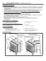
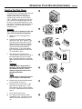
Symbols Used in this Manual
The illustration below details what the symbols used along the left margin indicate.
Requirement
¥
Step
1
Warning
!
Hint
Note
?
+
FEATURES AND SPECIFICATIONS
Installation Options:
¥
¥
¥
¥
¥
Features:
Residential or Mobile Home
Freestanding Stove or Insert
Bedroom Approved
Alcove Approved
Vertical or Horizontal Vent
¥
¥
¥
¥
¥
¥
¥
¥
Works During Power Outages (standing pilot)
High Efficiency
Optional Thermostat or Remote Control
Realistic "Wood Fire" Look
Convenient Operating Controls
Variable-Rate Heat Output
Quiet Blower for Effective Heat Distribution
Low Maintenance
Heating Specifications:
Approximate Heating Capacity (in square feet)*
High Burn Input Rate (In BTU's)
Low Burn Input Rate (In BTU's)
Efficiency**
AFUE (Annual Fuel Utilization Efficiency)
*
**
PAGE 5
Natural Gas
LP (Propane)
600 - 1600
38,500
18,700
81 %
72.4 %
600 - 1600
36,500
18,000
81.5 %
73 %
Heating capacity will vary with the home's floor plan and insulation, natural gas or Propane BTU rating, and outside temperature.
Efficiency rating is a product of thermal efficiency rating determined under continuous operation independent of installed system.
To measure the net BTU's, multiply the BTU input by the efficiency percentage.
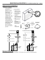
Dimensions
Measure Clearances
The base of the
from the Upper Top
starter section
is 1-3/8" below the
upper top.
The base of the starter section
is 1-3/8" below the upper top.
Weight: 175 Lbs.
23-3/4"
4-5/8"
8" Panels: 28"*
10" Panels: 30"*
12" Panels: 32"*
Pedestal: 31-1/2"
Brass, Cast Legs: 28"
Black Legs: 26-5/8"
8" Panels: 40"*
10" Panels: 44"*
12" Panels: 48"*
* Includes trim
Emissions:
Electrical Specifications:
4-5/8"
23-3/4"
18-5/8"
Fuel:
20-1/8"
13"*
5-3/4"*
The heater is designed either for natural gas or for propane. Check
the sticker on the top of the gas control valve.
This unit has passed the ANSI emission standards for vented room
heaters as tested by OMNI Environmental Services, Inc.
120 Volts, 1.3 Amps, 60 Hz (150 watts on high)
PAGE 6
STOVE INSTALLATION - For Qualified Installers Only!
Installation Preparation
! Failure to follow all of the requirements may result in property damage, bodily injury, or even death.
! This appliance must be installed in accordance with all local codes, if any; if not, follow ANSI Z223.1
and NFPA 54(88).
! In Manufactured or Mobile Homes must confirm with: In USA, Manufactured Home Construction
and Safety Standard, Title 24 CFR, Part 3280; In Canada, CSA Z240.4 and Gas-Equipped
Recreational Vehicles and Mobile Housing. This appliance may be installed in Manufactured
Housing only after the home is site located.
! This appliance is designed to operate on natural gas, or propane (LP).
! All exhaust gases must be vented outside the structure of the living-area. Combustion air is drawn
from outside the living-area structure.
! Notify your insurance company before hooking up this heater.
! The requirements listed below are divided into sections. All requirements must be met
simultaneously.
Items Required for Installation
¥
¥
Simpson Duravent, Silicone (see page 8 for part #'s)
Brass, Black, or Cast Legs or Pedestal
¥
¥
Legs or Pedestal (see page 32 for instructions)
Gas Hookup Equipment
¥
¥
Owner's Manual
Log Set (2 Logs, 2 Twigs, Embers)
4
5
6
Attach any optional equipment.
Connect the gas line. Connect the gas vent.
Follow the instructions under "Finalizing the
Installation" on pages 20 and 21.
Items Packed with the Chelan DV (700 DV)
¥
¥
Gas Inlet (3/8" Pipe)
Propane Conversion Kit
Order of Installation
1
2
3
Attach the legs or pedestal (see page 32)
If the heater is to use propane, install the propane
conversion kit (see pages 37 - 42)
Position the heater, use floor protection if needed
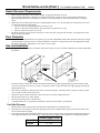
Stove Clearances
Straight Installations
When installed with this
clearance, the vent is 5-1/2"
from the back wall, 18-3/4"
from the side wall.
Corner Installations
When installed with this clearance, the
vent is 13-3/4" from the wall.
10" Min.
4" Min.
4" Min.
45¡
STOVE INSTALLATION (CONT.) - For Qualified Installers Only!
PAGE 7
Heater Placement Requirements
¥
¥
?
¥
Heater must be installed on a level surface capable of supporting the heater and vent
Due to the high temperature of the heater, it should be located out of traffic and away from furniture and draperies.
Heater must be placed so no combustibles are within, or can swing within 36" of the front of the heater (e.g. drapes,
doors)
When placed in a location where the floor to ceiling height is under 7 feet , the installation is considered an alcove and
must meet the following requirements:
¥ The alcove floor to ceiling height must be at least 58" tall
¥ The alcove must not be more than 48" deep (before the ceiling returns to 7 feet)
¥ The alcove must be at least 43-3/4" wide
The heater must not be placed so the vents below or above the door, along the sides of heater, or along the back of the
heater can become blocked.
Floor Protection
¥
When the stove is installed directly on carpeting, vinyl or other combustible material other than wood flooring or a high
pressure laminate wood floor, the stove must be installed on a metal or wood protection panel extending the full width
and depth of the heater (Minimum 23-3/4" wide by 18-5/8" deep).
Gas Line Installation
!
AAAAAAAA
AAAAAAAA
AAAAAAAA
A
A
A
AAAAAA
AAAAAAAA
AA
AAA
AAAAAA
AAAAAAAA
A
AAA
AAAAAA
AAA
A
A
AAAAAA
AAA
AAAAAA
A
A
AA
AAA
A
A AA
AAAAAA
AAA
AAAAAA
A
A
AAA
A
Rear
Panel
Use a pipe wrench
to tighten in place.
NOTE:
Apply thread
sealant prior to
installing.
!
¥
¥
¥
¥
¥
AAAAAAAA
AAAAAAAA
AAAAAAAA
A
AAAAAA
AAAAAAAA
AAA
AAAAAA
AAAAAAAA
A
AAA
AAAAAA
A
A
AAAAAAAAA
AAA
AAA
AAAAAA
AAAAAAAAAA
A
A
A
AAA
AAA
AAAAAA
AAA
AAAAAA
A
AA
The gas line must be installed in accordance with all local codes, if any; if not, follow ANSI Z223.1 and the requirements
listed below.
Gas Inlet
(3/8" diameter pipe)
1-1/2"
7-1/2"
Center of
Stove
12-7/8" Pedestal
9-1/2" Brass/Cast Legs
8" Steel Legs
The heater and gas control valve must be disconnected from the gas supply piping during any pressure testing of that
system at test pressures in excess of 1/2 psig. For pressures under 1/2 psig, isolate the gas supply piping by closing the
manual shutoff valve.
This heater is designed for natural gas but can be converted to propane. Check the sticker on the top of the gas control
valve to make sure the correct fuel is used.
Leak test all gas line joints and the gas control valve prior to and after starting the heater.
The gas inlet accepts a 3/8" F.P.T. Fitting
The location of the gas inlet is shown below
A manual shutoff valve is required for installation (it must be located within 3' of the heater)
Gas Inlet Pressure
¥
?
?
With the heater off, the inlet pressure must meet the requirements listed in the table below
If the pressure is not sufficient, make sure the piping used is large enough and the total gas load for the residence does
not exceed the amount supplied.
The supply regulator (the regulator that attaches directly to the residence inlet or to the propane tank) should supply gas
at the suggested input pressure listed below. Contact the local gas supplier if the regulator is at an improper pressure.
Natural Gas
Propane
Standard Input Pressure
7" W.C.
11" W.C.
PAGE 8
STOVE INSTALLATION (CONT.) - For Qualified Installers Only!
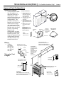
Vent Requirements
¥
When the vent passes through
a wall, a wall thimble is
required. When the vent
passes through a ceiling, a
support box or firestop is
required. When the vent
passes through the roof, a
roof flashing and storm collar
are required. Follow the
instructions provided with the
vent (from Duravent) for
installing these items.
Use a roof flashing and storm collar
whenever passing through the roof
(Duravent Part #953 & #943 or #943S)
Use a firestop spacer whenever
passing through a ceiling
(Duravent Part #963)
Minimum framing
for fire stop
Maintain a minimum 1"
clearance from vent to
any combustible (vent
is 6 5/8" diameter)
8-5/8"
Use a support box
on exposed vent
8-5/8"
Horizontal Vent
Requirements
Use a wall thimble
whenever passing
through a wall
(Duravent Part #942)
Minimum
Framing for
wall thimble
Horizontal Termination
(Duravent Part #984)
Maintain a minimum 1" clearance from vent
to any combustible (vent is 6 5/8" diameter)
6" Pipe Length, Black (interior)
9" Pipe Length, Black (interior)
12" Pipe Length, Galvanized
12" Pipe Length, Black (interior)
24" Pipe Length, Galvanized
24" Pipe Length, Black (interior)
36" Pipe Length, Galvanized
36" Pipe Length, Black (interior)
48" Pipe Length, Galvanized
48" Pipe Length, Black (interior)
11" to 14 5/8" Pipe, Adjustable, Black (interior)
981
982
984
950
991
Snorkel Termination (36" rise)
(for basement installations)
Snorkel Termination (14" rise)
(for basement installations)
Horizontal Square Termination
Vinyl Siding Standoff
Vertical Termination
942
940
941
943
943S
953
963
988
Elbows
990
990B
945
945B
Wall Thimble
Optional Wall Thimble Cover
Cathedral Ceiling Support Box
Flashing, 0/12 to 6/12 Roof Pitch
Flashing, 7/12 to 12/12 Roof Pitch
Storm Collar
Ceiling Firestop
Wall Strap
90¥ Elbow
90¥ Elbow, Black (interior)
45° Elbow
45° Elbow, Black (interior)
Apply high-temperature silicone to the inner and outer pipe before
assembling the sections (on the male, upper section). This seals
the inner pipe from the outer pipe. Slide the sections together and
turn 1/4 turn until the sections lock in place. Install three metal
screws through each joint to lock the outer section in place (see the
instructions included with the vent for further details).
¥ Horizontal sections require a 1/4" rise every 12" of travel
+ Exterior Vent Diameter = 6-5/8", Inner Vent Diameter = 4"
¥
¥
Vertical Vent
Requirements
Use Model GS Direct Vent manufactured by Simpson Dura-Vent only (or the Chimney Conversion
Kit - see Addendum #2). Follow the installation instructions included with the vent. For the nearest
Simpson Dura-Vent supplier, call (800) 835-4429. Part numbers and descriptions are listed below.
Straight Lengths
Vent Terminations
Penetration, Support Parts
908B
907B
906
906B
904
904B
903
903B
902
902B
911B
¥
Vertical Termination
(Duravent Part # 991)
e
¥
If the heater is installed at an
altitude over 3,000 feet the
flame quality will need to be
carefully evaluated. See
Addendum #1, "Altitude
Considerations", on page 43.
Apply a 1/8" (3 mm)
bead of hightemperature silicone
to the inner and
outer pipe. The
silicone must seal
the inner pipe from
the outer pipe.
on
!
lic
!
Always maintain the required 1" clearance (air space) to combustible materials to prevent a fire
hazard. Do not fill air spaces with insulation.
The gas appliance and vent system must be vented directly to the outside of the building, and never
be attached to a chimney serving a separate solid fuel or gas-burning appliance. Each direct vent gas
appliance must use it's own separate vent system.
Si
!
Sil
ico
ne
Horizontal sections require non-combustible support every three feet (e.g.: plumbing tape)
NOTE: You may screw the vent to the appliance (do not seal with silicone).
STOVE INSTALLATION (CONT.) - For Qualified Installers Only!
Approved Vent Configurations
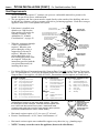
Restrictor Position
A vent restrictor is built
into the appliance to
adjust the flow rate of
exhaust gases. This
ensures proper flames for
the wide variety of vent
configurations. The
restrictor consists of a
butterfly valve below the
starter section of pipe
and an adjustment plate
with index holes used to
hold the valve in a fixed
position. Depending
upon the vent
configuration, you may
be required to adjust the
restrictor position. The
charts for Approved vent
configurations describe
which position the vent
restrictor must be in.
1 Determine the correct
restrictor position (see the
charts under "Approved
Vent Configurations" - the
stock position is #1).
2 Remove the screw with a
1/4" nutdriver (or
screwdriver).
3 Rotate the adjustment plate
clockwise until the correct
index hole is below the pivot
point.
4 Insert the screw into the
correct index hole and
tighten.
The eleven holes on the
restrictor plate
correspond to the eleven
restrictor positions.
AAAAAAAA
AAAAAAAA
AAAAAA
AA
AAAAAAAA
AAA
AAAAAAAA
AAAAAA
A
AAA
AAAAAAAA
AAAAAA
A
A
AAA
A
AAAAAA
A
AAAAAAAAA
AAAA
AAA
A
AAAAAA
A
A
AAA
A
AAAAAA
A
AAA
AAAAAAAA
A
Adjustment
Plate
NOTE:
Position #1 is the
fully open position
1 2 3
2 Elbow
maximum
(two 45° or
two 90°, not
one 45° and
one 90°)
4 5
This restrictor is
Rotate the
in Position #5.
adjustment
plate to change
the restrictor
position.
6
Index Holes
Screw
Vent Horizontal Run
(measure from the closest
edge of the starter section to
the end of the termination)
Elbows
¥
Pivot Point
11
10
9
8
7
1/4" Nutdriver
¥
To Adjust the Restrictor:
Elbows add 3" to the
length of the vent system.
3"
Side
View
9-5/8"
Measuring Vent
Lengths
3"
Vent Height is
calculated to the
top of the vent on
horizontal
terminations and
to the top of the
termination on
vertical
terminations.
1-1/2"
12-3/8" tall
with 1-1/2"
of overlap
Vent sections overlap
each other by 1-1/2"
1-1/2"
Vent Length
(4', 3', etc.)
Vent
Height
EXAMPLE:
Two 4' lengths are 7' 10-1/2" long,
but when attached to the vent system
add 7' 9" to the horizontal run.
The starter section is 1-3/8"
below the upper top.
8-3/4" wide
with 1-1/2" to
3-3/8" of overlap
PAGE 9
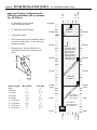
¥
10' Minimum System Height
(with or without offsets)
¥
33' Maximum System Height
0 feet
Approved Venting Configurations for
Vertical Terminations with (or without)
Two 45° Elbows
33' (max)
30 feet
¥
6' Maximum Offset
¥
The termination must fall within the shaded
area shown in the chart. Use the indicated
restrictor position.
¥
6' (max)
STOVE INSTALLATION (CONT.) - For Qualified Installers Only!
5 feet
PAGE 10
AAAAAA
AAAAAA
AAAAAA
AAAAAA
AAAAAA
AAAAAA
AAAAAA
AAAAAA
AAAAAA
AAAAAA
AAAAAA
AAAAAA
AAAAAA
AAAAAA
AAAAAA
AAAAAA
AAAAAA
AAAAAA
AAAAAA
Restrictor
Position # 7
30 feet
28' 6"
25 feet
If using offsets, use the table below to
calculate the vertical rise and horizontal
offset
Horizontal
Offset
20 feet
Vertical
Rise
Offset
Length
15 feet
NOTE:
Restrictor positions
are based upon lab
tests. The ideal
restrictor position
may vary slightly,
especially when the
termination is near
a demarkation line.
25 feet
20 feet
15 feet
Restrictor
Position # 5
10 feet
(min.)
The maximum
offset lengths is
two 4' sections.
5 feet
10 feet
(min.)
5 feet
Do not place an
offset directly off the
top of the heater.
0 feet
0 feet
6' (max)
Vert. Rise
1'
1' 7"
2' 4"
3'
3' 8"
4' 4"
5'
5' 9"
6' 9"
5 feet
Hor. Offset
5"
1'
1' 9"
2' 5"
3' 2"
3' 9"
4' 6"
5' 2"
6'
0 feet
Offset Length
None
1' Section
2' Section
3' Section
4' Section
4' + 1' Section
4' + 2' Section
4' + 3' Section
4' + 4' Section
STOVE INSTALLATION (CONT.) - For Qualified Installers Only!
PAGE 11
Approved Venting Configurations with a Horizontal Termination
If using a Snorkel Termination (14" or 36") add the snorkel height to the vertical height (snorkel
terminations are used primarily for basement installations).
¥
The termination must fall within the shaded area shown in the chart. Use the indicated restrictor
position.
11' (max)
10 feet
5 feet
12'(max)
¥
10 feet
A Minimum of 2' rise is required directly off of the heater
0 feet
¥
AAAAAAA
AAAAAAA
AAAAAAA
AAAAAAA
AAAAAAAAAA
AAAAAAAAAA
AAAAAAAAAA
11' (max)
10 feet
Restrictor
Position # 5
5 feet
Restrictor
Position # 1
5 feet
NOTE:
A minimum 2' rise is required
directly off of the stove.
0 feet
12'(max)
10 feet
5 feet
0 feet
0 feet
NOTE:
Horizontal sections require a 1/4" rise every 12" of travel.
NOTE:
Restrictor positions
are based upon lab
tests. The ideal
restrictor position may
vary slightly,
especially when the
termination is near a
demarkation line.
PAGE 12
STOVE INSTALLATION (CONT.) - For Qualified Installers Only!
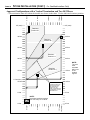
Approved Configurations with a Vertical Termination and Two 90° Elbows
35' (max)
15 feet
16'(max)
10 feet
5 feet
0 feet
¥ The termination must fall within the shaded area shown in the chart. Use the indicated restrictor position.
AAAAAAA
AAAAAAA
AAAAAAA
AAAAAAAAAAAAA
AAAAAAA
AAAAAAA
AAAAAAAAAAAAA
AAAAAAAAAAAAA
AAAAAAA
AAAAAAAAAAAAA
AAAAAAA
AAAAAAA
AAAAAAAAAAAAA
AAAAAAAAAAAAA
AAAAAAA
AAAAAAAAAAAAA
AAAAAAA
AAAAAAA
AAAAAAAAAAAAA
AAAAAAA
AAAAAAAAAAAAA
AAAAAAA
AAAAAAAAAAAAA
AAAAAAAAAAAAA
AAAAAAAAAAAAA
AAAAAAAAAAAAA
AAAAAAAAAAAAA
AAAAAAAAAAAAA
35' (max)
Restrictor
Position # 7
30 feet
30 feet
Restrictor
Position #6
25 feet
25 feet
Restrictor
Position # 5
20 feet
15 feet
11 feet (min.)
10 feet
Restrictor
Position # 4
20 feet
15 feet
10 feet
NOTE:
Restrictor positions are
based upon lab tests.
The ideal restrictor
position may vary
slightly, especially when
the termination is near a
demarkation line.
5 feet
5 feet
NOTE:
Horizontal sections require a
1/4" rise every 12" of travel.
16'(max)
15 feet
10 feet
5 feet
0 feet
0 feet
0 feet
NOTE:
The vent
must
terminate
within one
of the
shaded
regions.
STOVE INSTALLATION (CONT.) - For Qualified Installers Only!
PAGE 13
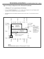
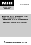
Horizontal Vent Termination Requirements (see the illustration below)
A
B
C
D
E
F
G
H
I
J
K
L
Minimum 9" (225 mm) clearance from any door or window
Roof
Minimum 12" (300 mm) above any grade, veranda, porch, deck or balcony
Surface
Minimum 12" (300 mm) from outside corner walls
Minimum 12" (300 mm) from inside corner walls
11Ó Min.
Roof
6Ó Min. Eaves
Minimum 11" (275 mm) clearance below unventilated soffits or roof surfaces
Minimum 18" (450 mm) clearance below ventilated soffits
Minimum 6" (150 mm) clearance from roof eaves
NOTE: Vinyl surfaces require 24" (600 mm)
Minimum 18" (450 mm) clearance below a veranda, porch, deck or balcony (must have two open sides)
Minimum 48" (1220 mm) clearance from any adjacent building
Minimum 84" (2130 mm) clearance above any grade when adjacent to public walkways or driveways
NOTE: may not be used over a walkway or driveway shared by an adjacent building
Minimum 48" (1220 mm) clearance from any mechanical air supply inlet, 72" (1820 mm) for Canada
Minimum 36" (910 mm) clearance above and 48" (1220 mm) below and to the sides of non-mechanical air supply inlet
Minimum 36" (910 mm) from the area above the meter/regulator (vent outlet)
Minimum 36" (910 mm) from the meter/regulator (vent outlet)
E
E
A
K
J
A
G
F
H
D
I
C
L
B
NOTE: Measure clearances to the nearest edge of the exhaust hood.
¥
¥
¥
Use the vinyl siding standoff (#950) when installing on an exterior with vinyl siding.
Vent termination must not be located where it will become plugged by snow or other material
These clearances meet UMC-1994 and the CNA/CGA-B149 code standards
Vertical Vent Termination Requirements (see the illustration below)
Use the vertical
termination (Part #991)
Use the
chart to the
right to
determine
the required
vent
termination
height.
Height
Roof
Pitch
Minimum Height*
Roof Pitch
1' (.3 M)*
Flat to 6/12
1.5' (.45 M)*
6/12 to 8/12
2' (.6 M)
8/12 to 9/12
2.5' (.75 M)
9/12 to 10/12
3.25' (1 M)
10/12 to 11/12
4' (1.2 M)
11/12 to 12/12
5' (1.5 M
12/12 to 14/12
6' (1.8 M)
14/12 to 16/12
7' (2.15 M)
16/12 to 18/12
7.5' (2.25 M)
18/12 to 20/12
8' (2.45 M)
20/12 or greater
* In Canada the
vent termination
must be a
minimum 2' (.6 M)
tall and 2' (.6 M)
above any portion
of the roof within
10' (3 M) of the
vent.
Electrical Connection
¥
Plug the power cord into a grounded 120 Volt outlet (do not remove the grounding plug).
PAGE 14
INSERT INSTALLATION - For Qualified Installers Only!
Installation Preparation
! Failure to follow all of the requirements may result in property damage, bodily injury, or even death.
! This appliance must be installed in accordance with all local codes, if any; if not, follow ANSI Z223.1
and NFPA 54(88).
! In Manufactured or Mobile Homes must confirm with: In USA, Manufactured Home Construction
and Safety Standard, Title 24 CFR, Part 3280; In Canada, CSA Z240.4 and Gas-Equipped
Recreational Vehicles and Mobile Housing. This appliance may be installed in Manufactured
Housing only after the home is site located.
! This appliance is designed to operate on natural gas, but may be converted to propane (LP).
! All exhaust gases must be vented outside the structure of the living-area. Combustion air is drawn
from outside the living-area structure.
! Notify your insurance company before hooking up this heater.
! The requirements listed below are divided into sections. All requirements must be met
simultaneously.
Items Required for Installation
¥
¥
¥
Insert Direct Vent Adapter (Travis Ind. Part # 98900122)
Simpson Dura-Vent Adapter & Silicone (Part # 923GK)
Simpson Dura-Vent Vertical Cap (Part # 991)
¥
¥
Surround Panels (see page 33)
Gas Hookup Equipment
¥
¥
Owner's Manual
Log Set (2 Logs, 2 Twigs, Embers)
4
5
Connect the gas line. Connect the gas vent.
Follow the instructions under "Finalizing the
Installation" on pages 20 and 21.
Install the surround panel kit.
Items Packed with the Chelan DV (700 DV)
¥
¥
Chelan DV (with black or brass door)
Propane Conversion Kit
Order of Installation
1
2
3
If the heater is to use propane, install the propane
conversion kit (see pages 37 - 42)
Re-route the power cord (if desired - see below)
Position the heater (see "Heater Placement")
6
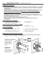
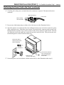
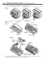
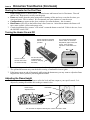
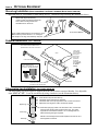
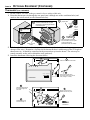
Re-Routing the Power Cord to the Front
The power cord may be re-routed to the front of the heater if desired (see the directions below).
1 Disconnect the strain relief at the rear of the heater.
TO REMOVE THE STRAIN RELIEF
Compress the strain relief
from the top and bottom
with a pair of slip joint
pliers. Once compressed,
the strain relief can be
pulled out.
Strain Relief
TO INSTALL THE
STRAIN RELIEF
Compress the strain relief
from the top and bottom
and insert it into the hole
until it locks in place.
Power Cord
INSERT INSTALLATION (CONT.) - For Qualified Installers Only!
PAGE 15
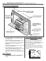
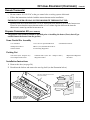
Re-Routing the Power Cord to the Front (continued)
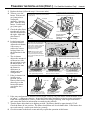
2
Carefully pull on the power cord until the molex connector is exposed. Disconnect the molex
connector.
Molex Connectors
Power Cord
Wires Leading
from the Heater
3
Pry out one of the button plugs on either side of the insert (see the illustration below).
4
Open the control cover and locate the wires leading from the power cord molex connector (green,
white, and black wires). Pull these wires forward. Insert the molex connector on the power cord
through the hole exposed in step 2 and re-connect to the molex connector on the heater. Tuck the
wire under the clip on the right side or under the gas inlet on the left side. This prevents the wire
from burning due to contact with the burner pan.
Remove the button
plug by prying it loose
with a screwdriver
Standard
Screwdriver
Button Plug
(found on both sides)
5
Tuck the wire under the
clip on the right side or
under the gas inlet on
the left side.
Secure the power cord to the heater with the strain relief (see the illustration under step 1).
PAGE 16
INSERT INSTALLATION (CONT.) - For Qualified Installers Only!
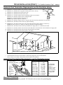
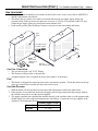
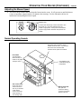
Insert Placement Requirements
Min. 29-3/4" WIde (includes 6" for gas
line installation)
The insert must be in place with
the gas line and vent attached
prior to installing the panels.
Min. 22-1/8" Tall
(includes 2" for
vent installation)
The Insert Must be
Placed 13" into the
Fireplace.
Use the leveling bolts for
fireplaces with recessed
floors (included with the
surround panels).
See the section "Gas Line
Installation" for details on the
location of the gas inlet.
¥
¥
¥
¥
¥
¥
Insert must be placed so no combustibles are within,
Zero-Clearance (Metal) Fireplace
or can swing within 36" of the front of the heater
Requirements:
(e.g. drapes, doors)
¥ The damper ("A") and grate (with logset) ("B")
The insert may be placed inside a masonry fireplace
must be removed (see the illustration below)
or listed zero-clearance (metal) fireplace
¥ The smoke shelf ("C"), internal baffles ("D"),
The insert must be installed in a level, undamaged
screen ("E"), masonry lining or refractory ("G" &
fireplace (damage must be repaired prior to
"I"), and metal or glass doors ("F") may be
installation).
removed (if applicable)
The insert must maintain 10" clearance to sidewalls ¥ The insulation ("H"), and any structured rigid
(measure from the upper top)
frame members (metal sides, floor, door frame,
Non-combustible facing (e.g. brick, tile) must
face of the fireplace, etc.) may not be removed
extend 8" minimum from the side and 12" to the top
or altered.
of the insert (measure from the upper top)
H
Combustible mantles must be a minimum 17-1/2"
A
above the top of the insert (measure from the upper
C
F
top)
Floor Protection
¥
Run the power cord to
either side of the insert
along the facing.
The heater must be installed on a non-combustible
hearth and may not extend over combustible
flooring
AA
A
A
AA
A
A
A
A
AAAA
AA
AAAAA
D
I
E
B
G
INSERT INSTALLATION (CONT.) - For Qualified Installers Only!
PAGE 17
Gas Line Install
!
!
¥
The gas line must be installed in accordance with all local codes, if any; if not, follow ANSI Z223.1
and the requirements listed below.
The heater and gas control valve must be disconnected from the gas supply piping during any
pressure testing of that system at test pressures in excess of 1/2 psig. For pressures under 1/2 psig,
isolate the gas supply piping by closing the manual shutoff valve.
Leak test all gas line joints and the gas control valve prior to and after starting the heater.
AAAAAAAA
AAAAAAAA
AAAAAA
A
A
AAA
AAAAAAAA
AAAAAA
A
AAAAAAAAA
AAAAAAAA
A
A
A
A
AAA
AAAAAA
AA
A
A
AA
AAA
AAAAAA
A
A
A
A
AA
AAA
AAAAAA
AAA
AAAAAA
A
AA
AAAAAAAAAA
Rear
Panel
Use a pipe wrench
to tighten in place.
NOTE:
Apply thread
sealant prior to
installing.
Gas Line Connection
¥
¥
¥
AAAAAAAA
AAAAAAAA
AA
AAAAAAAA
AAAAA
AAAAAAAA
AAA
AAAAA
AA
AAA
AA
AAAAA
AA
A
AAAAA
AAA
AA
AA
A
AA
AAA
AAAAA
AAAAA
A
AAA
AAA
AA
AAAAA
A
AA
AAA
A
1-1/2"
7-1/2"
Center of
Stove
1-5/8"
Gas Inlet
(3/8" diameter pipe)
The gas inlet accepts a 3/8" F.P.T. Fitting
The location of the gas inlet is shown below
A manual shutoff valve is required on the gas line within 3' of the heater
Fuel
¥
This heater is designed for natural gas but can be converted to propane. Check the sticker on the top
of the gas control valve to make sure the correct fuel is used.
Gas Inlet Pressure
¥
?
?
With the heater off, the inlet pressure must meet the requirements listed in the table below
If the pressure is not sufficient, make sure the piping used is large enough and the total gas load for
the residence does not exceed the amount supplied.
The supply regulator (the regulator that attaches directly to the residence inlet or to the propane tank)
should supply gas at the suggested input pressure listed below. Contact the local gas supplier if the
regulator is at an improper pressure.
Standard Input Pressure
Natural Gas
7" W.C.
Propane
11" W.C.
PAGE 18
INSERT INSTALLATION (CONT.) - For Qualified Installers Only!
Vent Requirements
!
The gas appliance and vent system must be vented directly to the outside of the building, and never
be attached to a chimney serving a separate solid fuel or gas-burning appliance. Each direct vent gas
appliance must use it's own separate vent system.
! Make sure the exhaust pipe (the inner pipe) on the heater connects to the exhaust portion of the cap
(the inner pipe). The illustrations below show how the flex liners should be attached.
Zero Clearance
! If the heater is
Masonry
high-temperature
Direct Vent Cap
(Metal) Fireplace
Fireplace Apply
installed at an
silicone to the 3" (75
(part # 991)
altitude over 3,000
mm) outlets on both
adapter boxes. Install
(1,000 M) feet the
the flex duct and secure
3" (75 mm)
Dura-Vent
Termination
Kit
flame quality will
with 2 screws.
Listed
(part # 923GK)
need to be carefully
B-vent liner
evaluated. See
Exhaust Only
Addendum #1,
Re-Lines
You may terminate the inlet
"Altitude
above the a block-off plate
that is sealed air-tight to the
Considerations", on
Hig
hwalls of the fireplace and to
SilicTemp.
one
page 43.
the vents. Combustion air is
then drawn down the
chimney. Any cracks or
? When using flexible
damage inside the chimney
must be repaired.
gas vent, do not
crimp or rupture the
Optional Block-Off Plate
liner when bending it
(non-combustible)
into chimney offsets
Dura-Vent Appliance
¥ When installed, the
Connector (Part # 923TCL)
vent must meet all of
p.
em
h-T
Hig
Hig ilicone
h
the vent
S
Sil -Tem
ico p.
ne
manufacturer's
requirements
Z.C. (Metal) firebox
Seal the adapter to the
heater with high+ There are two
temperature silicone
Use
the
telescoping
options for vent
(seal the outside only)
legs for raised
installation:
fireplaces.
Flex Re-Line
(Full Re-Line or Exhaust
Co-Axial Vent Re-Line
Apply a 1/8" (3 mm)
Only Re-Line):
bead of high-
AA
AA
AA
AA
AA
AA
AA
AA
AA
AA
AA
AA
AA
AA
AA
AAA
AA
AAA
AAA
AAA
AA
AA
AAA
AAAA
¥ Appliance Connector
(Part # 923TCL)
¥ 3" (75 mm) Listed
B-vent liner
¥ Termination Kit
(part # 923GK).
¥ Vertical Termination
(part # 991)
¥ Block-Off Plate
Co-Axial & Flex:
¥ Appliance Connector
(Part # 923TCL)
¥ 3" (75 mm) Listed
B-vent liner
¥ Block-Off Plate
¥ Termination Kit
(part # 923GK).
¥ Dura-Vent Co-Axial Vent and
Cap (see pg 8 for part #'s).
AAA
AA
A
AA
AAA
AA
A
AA
AAA
A
AA
AA
A
AAA
A
AA
AA
A
AA
AAA
A
AA
A
AA
AAA
AA
AA
A
AA
AAA
AA
AA
AAA
AA
A
AA
A
AA
A
AA
AAA
AA
A
AAA
AA
AA
A
A
AA
AA
AA
AA
AA
A
AAA
AA
AA
AAA
AA
Direct Vent Cap
(part # 991)
Zero Clearance
(Metal) Fireplace
(may be used
with a masonry
fireplace as well)
Optional cover plate
to keep rain out.
Direct Vent
Sections
Dura-Vent Termination Kit
(part # 923GK)
AA
A
AAA
AAA
AA
A
AAA
AAA
AAA
AA
AA
AA
AA
temperature silicone
to the inner pipe.
The silicone must
seal the inner pipe
from the outer pipe.
Apply high-temperature
silicone to the 3" (75 mm)
flex duct at both ends.
Install the flex duct and
secure with 2 screws.
Block-Off Plate
(non-combustible)
3" (75 mm)
Listed
B-vent liner
Dura-Vent Appliance
Connector (Part # 923TCL)
Hig
h
Sil -Tem
ico p.
ne
Use the
telescoping
legs for raised
fireplaces.
Hig
h
Sil -Tem
ico p.
ne
Seal the adapter box to the heater
with high-temperature silicone
(seal the outside only)
Z.C. (Metal)
firebox
Hig
h-T
Silic emp.
one
INSERT INSTALLATION (CONT.) - For Qualified Installers Only!
Approved Vent Configurations
Restrictor Position
A vent restrictor is
built into the
appliance to adjust
the flow rate of
exhaust gases. This
ensures proper
flames for the wide
variety of vent
configurations. The
restrictor consists of
a butterfly valve
below the starter
section of pipe and
an adjustment plate
with index holes used
to hold the valve in a
fixed position. Use
the illustrations
below to determine
the correct restrictor
position.
To Adjust the Restrictor:
1 Determine the correct
restrictor position (see the
charts under "Approved
Vent Configurations" - the
stock position is #1).
2 Remove the screw with a
1/4" nutdriver (or
screwdriver).
3 Rotate the adjustment plate
clockwise until the correct
index hole is below the pivot
point.
4 Insert the screw into the
correct index hole and
tighten.
The eleven holes on the
restrictor plate
correspond to the eleven
restrictor positions.
NOTE:
Position #1 is the
fully open position
AAAAAAA
AAAAAAA
AAAAAAA
AAAAA
AAA
AAA
AAAAAAA
AAAAA
A
A
AAA
AAAAAAA
AA
AAAAA
A
AAA
AA
AAAAA
A
AA
AAAAA
AA
A
AAA
AAA
AAAAA
A
AAA
AA
AAAAA
A
AAA
Adjustment
Plate
This restrictor is
Rotate the
in Position #5.
adjustment
plate to change
the restrictor
position.
Pivot Point
11
10
9
8
7
1/4" Nutdriver
¥
1 2 3
4 5
6
Index Holes
Screw
Full Flex Re-Line
Max. Ht. 30'
Min. Ht. 10'
10' - 24'
Use restrictor position 7
24' - 30'
Use restrictor position 5
AAA
AA
AA
AAA
AA
AAA
AA
AAA
AA
AAA
AA
AAA
AA
AAA
1' offset
(max.)
Co-Axial Vent Re-Line
Max. Ht. 30'
Min. Ht. 10'
10' - 16'
Use restrictor position 5
16' - 30'
Use restrictor position 7
AA
AA
AA
AA
1' offset
(max.)
Electrical Connection
¥
PAGE 19
Plug the power cord into a grounded 120 Volt outlet (do not remove the grounding plug).
PAGE 20
!
FINALIZING THE INSTALLATION - For Qualified Installers Only!
Turn the gas control valve to "OFF" prior to conducting any service.
Unscrew and remove the door handle.
1
Swing the door until it is open 90¡
Lift the door up and away from the heater.
Remove
the door.
NOTE: When re-installing, make sure the handle points away from the glass when finished.
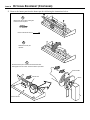
2
Install the
logs,
twigs, and
embers.
Burner Pan
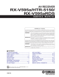
Log Installation
These clips keep the rear log
from tilting backwards.
The rear log contacts
the air deflectors.
The rear log
protrudes over the
burner pan on both
sides.
Re
ar
Fro
nt
The front log rests on
these platforms.
g(
lar
ge
st)
Lo
g
The front edge of
the front log rests
on this ledge.
The rear log has a
flat portion that
rests on this ledge.
Twig
Installation
Lo
Slide the front log all the way
back against the air deflector.
AAA AA
AAAAAA
A
AA
A
A
AA
A
A
Align the holes
in the left twig
over the pegs
on the front and
back logs.
Ember
Installation
Align the holes
in the right twig
over the pegs
on the left twig
and back log.
Place the embers on this ledge at the
front of the firebox . Do not place the
embers over the burner holes.
!
We recommend you purge the gas line at this time (with the glass removed). This allows gas to be
detected once it enters the firebox, ensuring gas does not build up.
FINALIZING THE INSTALLATION (CONT.) - For Qualified Installers Only!
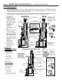
Replace the door (follow the step # 1 in reverse order).
To adjust the pilot flame, remove the cover screw (and
The pilot flame should impinge the top 3/8Ó (10 mm)
Turn on gas to the
gasket) and turn the needle valve. Clockwise lowers
of the thermopile. If it does not, you may need to
the flame while counter-clockwise raises it.
heater. Leak test all
turn the pilot up.
gas joints prior to
Thermopile
starting the
appliance. Start the
Pilot Hood
pilot. Start the main
burner. Leak test all
Needle Valve
gas joints again.
Micro (1/16Ó)
Standard
Check the pilot flame
Screwdriver
to make sure it looks
Cover Screw Gasket
like the illustration to
Cover Screw
the right. Adjust the
The cover screw and
gasket must be
pilot flame if
replaced to prevent gas
Standard
from leaking
necessary.
Thermocouple
3/8Ó (10 mm)
Screwdriver
Let the heater burn
Locate the air shutter adjustment
lever behind the gas control valve.
for fifteen minutes.
Move it up or down until the flame
Adjust the air shutter, looks correct. Pushing up gives the
Gas Control Valve
flame more air (making it bluer).
if necessary, to
Pulling it down cuts air down,
achieve the correct
making it more orange.
looking flame (see
NOTE: If the air control is all the
the illustration to the
way up, yet the flames remain
sooty, shut off gas to the fireplace
right).
and contact a qualified gas service
technician.
The air shutter
NOTE: The logs must be installed correctly to
monitor the flame while adjusting the air shutter.
adjusts the amount of
air that mixes with
the gas before it exits
the burner holes. It
is used to fine-tune
the flame for
differences in
Correct
Not Enough Air
Too Much Air
altitude and vent
If the flames are too tall or sooty on
If the flames are all blue and
Flames should be blue at the
configuration.
the ends, push up on the lever.
short, pull down the lever.
base, yellow-orange on the top.
If the air shutter is in
its fully open
Burner Ports
position, yet the
(consists of slots
and holes)
Burner Pan
flames remain sooty,
shut off gas to the
heater and contact
your dealer for a
remedy.
N
O
3
4
PAGE 21
PI L OT
AA
VENT
PILOT ADJ
OFF
6
FF
O
5
PI
LO
T
I
ON
LO
H
PILOT ADJ
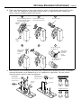
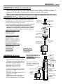
¥
!
The flames should burn right off
the top of the burner ports (if they
are too blue, adjust the air control).
!
7
8
If the flames are lifting, yet the
vent configuration is correct,
contact your dealer.
If the flames are ghosting, yet the
vent configuration is correct,
contact your dealer.
If the vent configuration is installed incorrectly the vent may cause the flames inside the heater to lift
or "ghost" Ð a dangerous situation. Inspect the flames after installation to insure proper performance.
If the vent configuration is correct, yet the flames are lifting or ghosting, shut off gas to the heater
and contact the dealer for information on remedying the problem.
Turn the flame adjust knob to its highest position - the flames should be approximately 12"tall.
Check the flame on low position. The flames should burn off of each burner hole. If the heater does
not work correctly, contact your dealer for a remedy.
Give this manual to the home owner and fully explain the operation of this heater.
PAGE 22
OPERATING YOUR HEATER
Before You Begin
!
Read this entire manual before you use your new heater (especially the section "Safety
Precautions" on pages 2 & 3). Failure to follow the instructions may result in property
damage, bodily injury, or even death.
Location of Controls - See explanation below
ON/OFF
Switch
The on/off switch
is located on the
right side of the
control cover.
ON
OF
The Pilot Flame can be
found below the back log
on the left side.
F
Swing the control cover to the
right to access the gas control
valve, igniter, and blower control.
OFF
PILOT
IGNITER
I
LO
FF
O
H
HI
BLOWER
O
N
VENT
Gas
Control
Valve
LO
P I L OT
PILOT ADJ
Gas Control
Knob
On/Off Switch
Gas Control Knob
Flame Adjust
Knob
Pilot Igniter
Blower Knob
This control is used to turn the main burner on and off.
This knob is used to control gas to the heater and for starting the pilot. There
are three positions, ON, OFF, & PILOT. The pointer directly below the knob
indicates the position this knob is in.
Flame Adjust Knob This knob controls the flame height from low ("LO") to high ("HI"). The
pointer to the upper left of the knob points to the position this knob is in.
Pilot Igniter
The pilot igniter is used only to start the pilot. When pressed, it sends an
electrical charge to the pilot assembly. This creates a blue spark directly next
to the pilot, igniting the pilot flame.
Blower Knob
This knob controls the speed of the internal convection blower that pushes the
heated air into the room.
? If using a remote control or thermostat, the On/Off Switch must be left "ON". Turning the On/Off
Switch "OFF" will keep the heater off always.
OPERATING YOUR HEATER (CONTINUED)
Starting The Pilot Flame
a
PI
When lighting or re-lighting the pilot, the
door must be removed (see page 20)
Remove the door (see page 20 for
details).
b
Push the gas control knob in slightly
and turn it to the "OFF" position. The
knob will not turn from "ON" to "OFF"
unless the knob is depressed slightly.
Wait five minutes to let any gas that
may have accumulated inside the
firebox escape. If you smell leaking
gas, follow the directions on the cover
"IF YOU SMELL GAS".
PILOT ADJ
N
a
AA
AA
AA
AAA
AAA
OT
L
b
5 minutes
OFF
WARNING:
ON
The pilot flame is required to ignite the main
burners (it also plays a safety role). It
should be left on once lit. It will stay lit
unless the gas control valve is turned to
"OFF". However, the pilot will go out if the
gas is shut off, the propane tank runs out
(or low) or if the stove malfunctions. If the
pilot turns off frequently, call your dealer for
information. To start the pilot follow the
directions below:
O
P I L OT
N
PILOT ADJ
O
30 seconds
AA
AAA
AA
AAA
FF
d
O
P I L OT
O
N
PILOT ADJ
e
?
FF
O
P I L OT
WARNING:
If the pilot does not light after 15
seconds, release the knob and call
your dealer for service. Do not
attempt to light pilot until service
has been performed.
FF
Turn the gas control knob to the
"PILOT" position and press the knob in,
this will allow gas to flow to the pilot
light. Press the red button on the pilot
igniter repeatedly until you see the pilot
light.
c
O
c
PILOT
IGNITER
PILOT ADJ
NOTE:
You may wish to remove the log set
to gain a better view of the pilot.
Release the gas control knob. If the
pilot goes out, repeat step C. If the
pilot refuses to stay lit, call your dealer
for service. With the pilot lit, proceed to
step ÒfÓ.
f
Close and secure the door.
g
Turn the gas control knob counterclockwise to "ON". The pilot is now lit
and the heater can be turned on and
off.
OFF
e
f
PI
g
PILOT ADJ
T
LO
Keep the gas control knob depressed
for 30 seconds once it is lit.
ON
d
PAGE 23
PAGE 24
OPERATING YOUR HEATER (CONTINUED)
Starting the Heater for the First Time
¥
Paint Curing insures a durable finish. Start the heater and burn on low for 20 minutes. Turn off
and let cool. Repeat twice to fully cure the paint.
+ Fumes and smoke from the paint curing and oil burning off the steel may occur the first time you
start your heater. This is normal. We recommend you open windows to vent the room.
+ Condensation may appear on the glass each time you start the heater - this is normal.
+ Blue Flames will occur on the heater when it first comes on. After fifteen minutes the flames will
turn a more realistic yellow and orange color.
? Certain installations use a remote "wall switch" to turn the heater on and off. If this is the case, leave
the ON/OFF switch "ON".
Turning the Heater On and Off
After the pilot has been started...
See the instructions included
with the remote for details on
operation.
ON
OF
Use this switch to
turn the main burner
on and off manually.
!
?
For systems with thermostats,
use this switch to control the
temperature (right is hotter, left
cooler). Some systems
require the on/off switch to be
on.
F
See the instructions
included with the
remote for changing
the battery.
Do not place any combustible items on top of or directly in front of the heater, even temporarily.
The optional thermostat may start the heater causing a combustible item to ignite.
If the heater turns on and off frequently while using the thermostat, you may want to adjust the flame
height down until it produces just enough heat needed.
Adjusting the Flame Height
Flame Height
Adjustment Knob
Index Mark
VENT
+ Your heater has an adjustable flame to tailor the look and heat output to your specific needs. It is
adjusted by turning the middle dial on the gas control valve.
I
N
O
I
LO
FF
O
H
PI L OT
PILOT ADJ
Turn clockwise to adjust the flame higher, counter-clockwise to lower.
LO
VENT
H
OPERATING YOUR HEATER (CONTINUED)
PAGE 25
Adjusting the Blower Speed
+ The blower helps transfer the heat from the heater into the room. It will not turn on until the heater
is up to temperature (approximately 10 minutes after starting). See the illustration below for
instructions on adjusting the blower speed.
Blower Knob
OFF HI
LO
BLOWER
PILOT
IGNITER
Turn the knob all the way counter-clockwise to turn
the blower off. One click clockwise turns the
blower to high speed. Turning the knob clockwise
from the high position decreases the speed of the
blower.
Normal Operating Sounds
Blower
This heater uses a blower to push
heated air into the room. You will hear
the sound of air movement that
increases as the speed is increased.
Pilot Flame
The pilot flame,
which remains on,
makes a very slight
"whisper" sound.
Gas Control Valve
As the gas control
valve is turned on
and off you will hear
a dull clicking
sound. This is the
valve opening up
and shutting down.
The appliance may
creak with change of
temperature.
Blower Snap Disk
This part can
produce a clicking
sound as it turns the
blower on and off.
PAGE 26
MAINTAINING YOUR HEATER
Cleaning Your Heater
!
The optional brass door may be cleaned with a non-abrasive polish (such as Flitz). The brass trim
is anodized and should not be polished.
Yearly Service Procedure
!
Failure to inspect and maintain the heater may lead to improper combustion and a potentially
dangerous situation. We recommend the following procedures be done by a qualified technician.
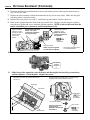
1 Check the pilot flame. It should engulf approximately 3/8" of the top of the thermocouple (see
illustration below). If it does not, contact your dealer for service.
2 Shut off gas to the heater by turning the gas control knob to "OFF" (see step A under "Starting the
Pilot" on page 23). Let the heater cool for 15 minutes. Remove the door (see step 1 on page 20).
3 Remove the logs, twigs and embers (see page 20 - NOTE: the logs are fragile). If any log is
cracked or deteriorated, replace it when re-installing. Check the logs for sooting. A small amount of
soot along the bottom of the logs is normal. If excessive sooting is found, the heater will require
adjustment. Contact your dealer.
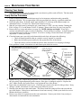
4 Clean the burner pan (especially in the burner holes and slots) and inspect the following:
¥ Check for burner pan holes that are cracked, severely warped, or corroded.
¥ Make sure the burner pan assembly fits flat against the floor of the firebox.
¥ Check the firebox and area around the pilot to make sure there is no warping or damage.
If any problem is found, discontinue use and contact your dealer for service.
Before Disassembly: Check the pilot flame. It should
impinge the top 3/8Ó of the thermopile and engulf the
thermocouple.
Check the walls and
ceiling of the firebox
for deterioration.
Make sure the
burner pan seals
against the floor
of the firebox.
Thermopile
Pilot Hood
3/8Ó
5
6
7
8
Thermocouple
Burner Pan
Check the burner
holes and slots.
Replace the log set. Inspect the glass gasket. If it is deteriorated, replace. It may be re-attached to
the glass using high-temperature gasket cement. If the glass is damaged, replace it. Replace the
door. Make sure the door gasket forms a seal against the face of the heater.
Inspect the area behind the control cover. Check the gas control valve and all of the gas lines. If any
damage is found, discontinue use and contact your dealer for service.
Start the pilot and turn on the main burner. The flames should be orange/yellow and not touch the
top of the firebox. If the pilot or main burners do not burn correctly, contact your dealer for service.
Monitor the blower operation.
Remove any debris or vegetation near the vent termination. Contact your dealer if any sooting or
deterioration is found near the vent termination.
TROUBLESHOOTING
Problem:
Pilot Will Not Flame
Possible Cause:
PAGE 27
Don't Call for Service
Until You:
A gas shut off valve is turned off
Check all gas shut off valves
The gas control knob isn't turned to "PILOT"
See "Starting the Pilot Flame" Pg 23
The valve control knob isn't pushed in
See "Starting the Pilot Flame" Pg 23
The igniter wasn't pressed repeatedly
See "Starting the Pilot Flame" Pg 23
The pilot flame has gone out
See "Starting the Pilot Flame" Pg 23
The gas control valve is turned to "PILOT" or "OFF"
See "Starting the Pilot Flame" Pg 23
The ON/OFF switch is turned to "OFF"
Turn the ON/OFF switch to "ON"
The remote control is not working correctly
Replace the batteries
The thermostat is disconnected or set too high
Set the thermostat to a lower temperature
The pilot light has gone out
See "Starting the Pilot Flame" Pg 23
The gas control valve is turned to "PILOT" or "OFF"
See "Starting the Pilot Flame" Pg 23
The ON/OFF switch is turned to "OFF"
Turn the ON/OFF switch to "ON"
The remote is too far away from the heater
Use the remote closer to the heater
The remote control receiver is turned "OFF"
See the remote control instructions
One of the two remote control batteries is dead
See the remote control instructions
The pilot flame has gone out
See "Starting the Pilot Flame" Pg 23
The gas control valve is turned to "PILOT" or "OFF"
See "Starting the Pilot Flame" Pg 23
The ON/OFF switch is turned to "OFF"
Turn the ON/OFF switch to "ON"
The thermostat is set too high
Set the thermostat to a lower temperature
Blower Does Not
Operate
The heater is not getting electricity
Check the outlet switch
The heater is not up to temperature
See "Operating Your Heater"
Flames Are Too Blue
The heater has just been started
This is normal - see "Starting the Heater
for the First Time"
Flames Are Too Short
(Under 6")
The flame height may be turned too low
Turn the flame height to "HI" See "Adjusting the Flame Height"
Main Burners Will Not
Start
Remote Control Does
Not Work
Thermostat Does Not
Work
PAGE 28
TROUBLESHOOTING (CONTINUED)
How this Heater Works
!
This heater was designed with safety as the primary concern. Many of the components inside this
heater are for safety purposes. Therefore, only certified gas service technicians should service this
heater.
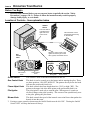
What Turns the Main Burners On and Off
This electricity is
used to operate the
main burners.
FF
O
H
LO I
O
VENT
N
When heated, the thermopile
generates electricity (a very small
amount, measured in "Millivolts").
P I L OT
PILOT ADJ
The main burners
are switched on and
off using the
electricity generated
by the thermopile.
The ON/OFF switch,
remote control, or
thermostat control
the circuit to the main
burner.
MAIN BURNER
This heater uses a millivolt system to control its operation (a millivolt is a very small amount of
electricity). The thermopile and thermocouple generate electricity when heated by the pilot flame.
This electricity is used to operate the gas valve. Without enough electricity, the gas valve will not
turn on. That is why when starting the pilot the gas control knob has to be pressed in long enough
for the thermocouple to heat up and generate enough electricity. The thermopile provides power for
the ON/OFF switch, remote control, or thermostat (see the illustration below). Because the
thermopile generates the electricity needed to turn the heater on and off, this heater can be operated
when the power is out (although the blower will not run).
ON
OFF
What Prevents Gas Buildup
+ This appliance utilizes a high-technology gas valve in conjunction with a pilot flame to ensure no
gas builds up inside the firebox.
+ The thermocouple (next to the pilot) senses when the pilot flame is lit. If the pilot flame goes out,
this thermocouple no longer generates electricity, causing the gas valve to automatically shut off all
gas to the heater, preventing the pilot from spilling gas into the firebox.
FF
O
LO
H
I
O
VENT
N
Pilot Flame
The pilot flame is a time-proven
component that eliminates the possibility
of gas buildup inside the firebox.
Gas Valve
This high-technology valve automatically
shuts off all gas if it does not receive a signal
from the thermocouple. If any component is
damged or sensing a malfunction, or if the
wiring is damaged, it will shut off all gas.
I
P L OT
PILOT ADJ
Thermocouple
The thermocouple generates a small
amount of electricity. If the pilot flame
goes out, the gas valve automatically
shuts off all gas.
External Shut Off Valve
This valve is placed on the gas line
to shut off gas to the appliance
during maintenance procedures.
Ceramic Glass
The glass in your heater is the most
durable glass available. It has been
tested to be extremely resistant to
breakage and temperature changes.
TROUBLESHOOTING (CONTINUED)
PAGE 29
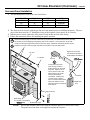
Why Nothing Should Be Placed Against the Heater
Your heater has a grill on the sides, bottom, and top that must not be blocked. These grills are
used to draw room air over the hottest parts of the heater and distribute the warmed air into the
room. If they are blocked, the heater will not heat as well and may become too hot internally.
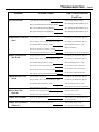
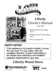
Wiring Diagram
Thermopile
A
Gas Control Valve
Brown
EPU
terminal
A
AA
Red
White
Red
Jumper Wire
(Manual
Operation)
Green
Piezo Igniter
Orange
Thermocouple
Copper Co-Axial Wire
On/Off
Switch
Chassis
Ground
Blower
Motor
Black
Green
White
Black
Optional
Thermostat
Optional
Remote
Control
Black
Black
White
120 Volt
Grounded A.C.
Power Supply
White
Black
Blower
Thermodisk
Blower
Rheostat
120 V.
Blower
Circuit
PAGE 30
WARRANTY
To register your TRAVIS INDUSTRIES, INC. 7 Year Warranty, complete the enclosed warranty card and mail it within ten (10) days of the appliance
purchase date to: TRAVIS INDUSTRIES, INC., 10850 117th Place N.E., Kirkland, Washington 98033. TRAVIS INDUSTRIES, INC. warrants this gas
appliance (appliance is defined as the equipment manufactured by Travis Industries, Inc.) to be defect-free in material and workmanship to the original
purchaser from the date of purchase as follows:
Years 1 & 2 - COVERAGE: PARTS & LABOR
Burner Assembly:
Ceramic Glass
Accessories
Burner, Burner Pan, Air Shutter Assembly, Main Burner
Orifice
Glass (breakage from thermal shock)
Legs, Pedestal, Panels, Cast Firebacks, Shell
Assembly
Firebox Assembly:
Ceramic Logs
Adjustable Air Restrictor, Pressure Relief Mechanisms
(direct vents only), Glass Attachment Mechanism
Log Set, Coals, Ember Strip (Steel Fiber)
Gas Control Assembly
Adjustable control valve, millivolt wiring and connectors
(located within the metal heater structure), thermopile,
thermocouple, pilot hood, orifices, pilot gas line, piezo
ignitor
Optional Brass Door
Re-Installation Allowance
Solid Brass Door (see ÒConditions and ExclusionsÓ # 9)
In cases where heater must be removed from home for
repairs, a partial cost of re-installation is covered (preauthorization required)
Gold Plating
Gold or Nickel Door, Optional Grill (see ÒConditions & ExclusionsÓ
#9)
Electrical Assembly:
Blower, wiring harness, snap discs, rheostat speed control
Exclusions:
Convection Heat Exchanger
One-Way Freight Allowance
One-way freight allowance on pre-authorized repair
done at factory is covered.
Paint, Gasketing
Years 3 THROUGH 5 - COVERAGE: PARTS & LABOR
Burner Assembly:
Firebox Assembly:
Convection Heat Exchanger
Burner, Burner Pan, Air Shutter Assembly, Main Burner
Orifice
Adjustable Air Restrictor, Pressure Relief
Mechanisms (direct vents only), Glass Attachment
Mechanism
One-Way Freight Allowance
Optional Brass Door
Solid Brass Door (see ÒConditions and ExclusionsÓ # 9)
Exclusions:
One-way freight allowance on pre-authorized repair
done at factory is covered.
Paint, Gasketing, Electrical Assembly, Gas Control Assembly, Ceramic Glass, Ceramic Logs, Gold & Nickel Plating, Accessories, ReInstallation Allowance
Years 6 & 7 - COVERAGE: PARTS ONLY
Burner Assembly:
Firebox Assembly:
Optional Brass Door
Burner, Burner Pan, Air Shutter Assembly,
Main Burner Orifice
Adjustable Air Restrictor, Pressure Relief Mechanisms
(direct vents only), Glass Attachment Mechanism
Solid Brass Door (see ÒConditions and ExclusionsÓ
# 9)
Exclusions:
Paint, Gasketing, Electrical Assembly, Gas Control Assembly, Ceramic Glass, Ceramic Logs, Gold & Nickel Plating, Accessories,
Convection Heat Exchanger, Re-Installation Allowance, One-Way Freight Allowance, Labor
CONDITIONS & EXCLUSIONS
1.
2.
3.
4.
5.
6.
7.
8.
9.
10.
11.
12.
13.
14.
15.
16.
17.
This new gas appliance must be installed by a qualified gas appliance technician. It must be installed, operated, and maintained at all times in accordance with the instructions in the
OwnerÕs Manual. Any alteration, willful abuse, accident, neglect, or misuse of the product shall nullify this warranty.
This warranty is nontransferable, and is made to the ORIGINAL purchaser, provided that the purchase was made through an authorized TRAVIS dealer.
Discoloration and some minor expansion, contraction, or movement of certain parts and resulting noise, is normal and not a defect and, therefore, not covered under warranty. The
installer must ensure the appliance is burning as per the rating tag at the time of installation. Over-firing (operation above the listed BTU rate) of this appliance can cause serious damage
and will nullify this warranty.
The warranty, as outlined within this document, does not apply to the chimney components or other Non-Travis accessories used in conjunction with the installation of this product. If in
doubt as to the extent of this warranty, contact your authorized TRAVIS retailer before installation.
Travis Industries will not be responsible for inadequate performance caused by environmental conditions such as nearby trees, buildings, roof tops, wind, hills or mountains or negative
pressure or other influences from mechanical systems such as furnaces, fans, clothes dryers, etc.
This Warranty is void if:
a.
The unit has been operated in atmospheres contaminated by chlorine, fluorine or other damaging chemicals.
b.
The unit is subject to submersion in water or prolonged periods of dampness or condensation.
c.
Any damage to the unit, combustion chamber, heat exchanger or other components due to water, or weather damage which is the result of, but not limited to, improper
chimney/venting installation.
Exclusions to this 7 Year Warranty include: injury, loss of use, damage, failure to function due to accident, negligence, misuse, improper installation, alteration or adjustment of the
manufacturer's settings of components, lack of proper and regular maintenance, damage incurred while the appliance is in transit, alteration, or act of God.
This 7 Year warranty excludes damage caused by normal wear and tear, such as paint discoloration or chipping, worn or torn gasketing, corroded or cracked logs, embers, etc. Also
excluded is damage to the unit caused by abuse, improper installation, modification of the unit, drilling of the orifices, or the use of fuel other than that for which the unit is configured.
Units are shipped for natural gas and must be converted to propane using the included conversion kit. Confirm fuel configuration with your installer.
Damage to gold, nickel, or brass surfaces caused by fingerprints, scratches, melted items, or other external sources left on the surface is not covered in this warranty. Damage from the
use of cleaners other than denatured alcohol on gold or nickel is not covered in this warranty. Damage from the use of abrasive cleaners on brass is not covered in this warranty.
TRAVIS INDUSTRIES, INC. is free of liability for any damages caused by the appliance, as well as inconvenience expenses and materials. Incidental or consequential damages are not
covered by this warranty. In some states, the exclusion of incidental or consequential damage may not apply.
This warranty does not cover any loss or damage incurred by the use or removal of any component or apparatus to or from the gas appliance without the express written permission of
TRAVIS INDUSTRIES, INC. and bearing a TRAVIS INDUSTRIES, INC. label of approval.
Any statement or representation of TRAVIS products and their performance contained in TRAVIS advertising, packaging literature, or printed material is not part of this 7 year warranty.
This warranty is automatically voided if the applianceÕs serial number has been removed or altered in any way. If the appliance is used for commercial purposes, it is excluded from this
warranty.
No dealer, distributor, or similar person has the authority to represent or warrant TRAVIS products beyond the terms contained within this warranty. TRAVIS INDUSTRIES, INC. assumes
no liability for such warranties or representations.
Travis Industries will not cover the cost of the removal or re-installation of hearths, facing, mantels, venting or other components.
If for any reason any section of this warranty is declared invalid, the balance of the warranty remains in effect and all other clauses shall remain in effect.
THIS 7 YEAR WARRANTY IS THE ONLY WARRANTY SUPPLIED BY TRAVIS INDUSTRIES, INC., THE MANUFACTURER OF THE APPLIANCE. ALL OTHER WARRANTIES,
WHETHER EXPRESS OR IMPLIED, ARE HEREBY EXPRESSLY DISCLAIMED AND PURCHASERÕS RECOURSE IS EXPRESSLY LIMITED TO THE WARRANTIES SET FORTH
HEREIN.
IF WARRANTY SERVICE IS NEEDED:
1.
2.
3.
4.
If you discover a problem that you believe is covered by this warranty, you MUST REPORT it to your TRAVIS dealer WITHIN 30 DAYS, giving them proof of purchase, the purchase date,
and the model name and serial number.
Travis Industries has the option of either repairing or replacing the defective component.
If your dealer is unable to repair your applianceÕs defect, he may process a warranty claim through TRAVIS INDUSTRIES, INC., including the name of the dealership where you
purchased the appliance, a copy of your receipt showing the date of the applianceÕs purchase, and the serial number on your appliance. At that time, you may be asked to ship your
appliance, freight charges prepaid, to TRAVIS INDUSTRIES, INC. TRAVIS INDUSTRIES, INC., at its option, will repair or replace, free of charge, your TRAVIS appliance if it is found to
be defective in material or workmanship within the time frame stated within this 7 year warranty. TRAVIS INDUSTRIES, INC. will return your appliance, freight charges (years 1 to 5)
prepaid by TRAVIS INDUSTRIES, INC., to your regional distributor, or dealership.
Check with your dealer in advance for any costs to you, when arranging a warranty call. Dealers may require you to pay a service or trip charges for any warranty work. This charge can
vary from store to store.
LISTING INFORMATION
The safety label can be found on the back of the heater. A copy is shown below.
Tested &
Listed by
700 DV
Beaverton,
OR. USA
TM
Report No. 028-S-15-5
Listed Gas-Fired
Direct Vent Wall Furnace
and Fireplace Insert
Tested and certified by OMNI-Test, Inc. to the following standards:
USA: ANSI Z21.44-1992 Gas-Fired Gravity and Fan type Direct-Vent Wall Furnace, and applicable sections of Z21.11.1-1991 Gas-Fired Vented Room Heaters.
CANADA: CAN 1-2.19-M81 Gas-Fired Direct-Vent Wall Furnace, CGA IR41 Direct-Vent Gas Fireplace, CGA IR55 additional requirements for Direct-Vent
Fireplaces, and CAN/CGA 2.17-M91 “Gas-Fired Appliances for use at High Altitudes”.
Must be installed in accordance with all local codes, if any; if not, follow ANSI Z223.1-1992 and NFPA 54(88). Installation in Manufactured or Mobile Homes must
conform with: In USA, Manufactured Home Construction and Safety Standard, Title 24 CFR, Part 3280; In Canada, CSA Z240.4 and Gas-Equipped Recreational
Vehicles and Mobile Housing. This model is designed to operate on natural gas, or propane (LP). This appliance uses a millivolt-type control system consisting of
a gas control valve/regulator, a standing pilot burner assembly, a thermopile, a piezo ignitor, and the ON/OFF switch. THIS UNIT DOES NOT REQUIRE 110 VOLT
POWER TO OPERATE. All exhaust gases must be vented outside the structure of the living-area. Combustion air is drawn from outside the living-area structure.
This appliance may be installed in Manufactured Housing only after the home is site located.
WARNINGS:
Improper installation, adjustment, alteration, service or maintenance can cause injury or property damage. Refer to the information in the owner’s and installation
manual provided with this appliance. For assistance or additional information consult a qualified installer, service agency or the gas supplier.
Installation and repair should be performed by a qualified service person. The appliance should be inspected before use and at least annually by a qualified
service person. More frequent cleaning may be required where excessive lint from material like carpeting and bedding is present. The control compartment, the
burner compartment and all circulating air passageways of the appliance must be kept clean and clear at all times.
Due to high temperatures, the appliance should be located out of traffic and away from furniture and draperies.
This appliance must not be connected to a chimney flue servicing a separate solid fuel burning appliance.
This room heater is a Direct-Vent Gas-Fired appliance. DO NOT burn wood or other material in this heater.
Children and adults should be alerted to the hazards of high surface temperature and should stay away to avoid flesh burns or clothing ignition.
Young children should be carefully supervised at all times when they are in the same room as the appliance.
CAUTION:
All safety screen or guard components removed for servicing, must be replaced prior to operating the appliance.
Clothing or other flammable material should not be placed on or near the appliance.
Risk of electrical shock. Switch the household breaker off or remove fuse before servicing unit.
Use Simpson DURA-VENT direct vent system (Model GS) to vent this appliance to the exterior (direct discharge only without duct connection).
Minimum Clearances to Combustibles
Unit to Sidewall . . . . . . . . . . .
Unit to Backwall . . . . . . . . . .
Unit to Cornerwall . . . . . . . .
Front of Unit . . . . . . . . . . . . .
Alcove Min. Height . . . . . . . .
Alcove Max Depth . . . . . . . .
Alcove Min Width . . . . . . . . .
10”
4”
4”
36”
58”
45”
44”
Mantle Height Above Unit . . . . . 17.5”
Side Facing to Unit . . . . . . . . . . 8”
Top Facing to Unit . . . . . . . . . . . 8”
Hearth Extension Front . . . . . . . 0”
Hearth Extension Side . . . . . . . . 0”
1996
1997
1998
Jan.
Feb.
Mar.
Apr.
May
Jun.
Jul.
Aug.
Sep.
L.P.
36,500
18,000
#50
11”
13”
10”
2.7”
N.G.
38,500
18,700
#32
5.5”
7”
3.5”
1”
This room heater is equipped at the factory for use with natural gas. If conversion to
propane (LP) fuel is desired the optional factory conversion kit #98900746 must be used.
Blower Electrical Rating: 115V, 1.5 Amps, 60 Hz
FAN TYPE VENTED CIRCULATOR
Manufacture
Date:
Input Rate on “HI” (BTU/Hr).............................
Input Rate on “LO” (BTU/Hr) ...........................
Main Burner Orifice (DMS)...............................
Minimum Inlet Pressure (inches W.C.) ...........
Maximum Inlet Pressure (inches W.C.) ..........
Manifold Pressure on “HI” (inches W.C.) .......
Manifold Pressure on “LO” (inches W.C.)......
Oct.
Nov.
Dec.
10850 117th Pl. N.E. Kirkland, WA 98033
IGN
PAGE 31
PAGE 32
OPTIONAL EQUIPMENT
Stove Leg Installation (Brass # 99200500, Cast Black # 99200800, Black Steel # 99200100)
Raise the stove 8" (use lumber or other sturdy device). Attach each leg following the instructions below.
Attach each leg to the stove by
inserting a bolt and washer through the
hole or slot in the leg and into the
threaded hole on the stove.
9/16" Socket Wrench
These rubber-tipped bolts are for leveling the stove.
Make sure they contact the floor. Do not adjust
with weight on the legs, the rubber tips may tear.
Pedestal Installation (Part # 99200109)
Use a 9/16" wrench to attach the two
pedestal bolts to the bottom of the stove.
The lag bolts
and washers
may be inserted
through the
holes in the
base of the
pedestal to
anchor the
pedestal to the
floor (required
for mobile
homes).
Stove
9/16" Socket Wrench
AAAA
AAAA
AAAA
AA
AA
AA
The cover plates, screen,
insulation, and staples are used for
wood stoves - discard these items.
Pedestal
The dowels insert onto the front and
back edge of the pedestal base.
Telescoping Leg Installation (Part number 99200120)
The telescoping legs are designed to support the front end of inserts on raised hearths. It is adjustable
from 4 5/8" to 7 1/2". It can be cut shorter by using a hacksaw (see the illustration below).
Upper Leg
Lower Leg
End Cap
AAA
A
B
C
D
Insert the end cap into the lower leg
Thread the upper and lower leg together.
Thread the bolt on the top leg into the front corners of the insert.
Adjust the lower leg down until it contacts the hearth.
If the telescoping leg needs to be less than 4 5/8", unscrew the
lower leg and shorten each leg with a hack saw. The upper
segment has a threaded rod inside. Do not damage this rod
while shortening the upper segment.
NOTE: The total length removed will equal the amount cut off of
both segments combined.
OPTIONAL EQUIPMENT (CONTINUED)
PAGE 33
Surround Panel Installation
+ The surround panels come in the sizes listed below
2
3
HEIGHT
WIDTH
PART #
8"
10"
12"
28"
30"
32"
40"
44"
48"
99300259
99300260
99300261
The insert must be in place with the gas line and vent attached prior to installing the panels. The rear
edge of the insert must be 13" behind the facing of the fireplace for the panels to fit correctly.
Run the power cord to either side of the insert several inches in front of the facing.
Follow the instructions below for installing the panels and trim.
a
Remove the button plugs on the side of the insert (2 on each side). Pre-thread these holes by inserting
the screws (10-24 self-tapping) and tightening with a 5/16" nutdriver. Line up the holes on the side
panels over the holes exposed by removing the button plugs. Attach the side panels with the screws.
b
Install the top panel so the two joggle clips slide over the tab on top of the side panels..
AA
AA
AA
Tighten the set screws
from the back side with a
small standard screwdriver
Top Trim
"L" Bracket
c
Top
Panel
Construct the panel trim.
Insert one leg of each "L"
bracket into the top and side
trim piece. Align the trim to
form a precise corner, then
tighten the two set screws
with a small standard
screwdriver. Slide the trim
over the panels. Attach a
piece of included double-back
tape to the bottom of each
side trim to keep it from flaring
at the bottom.
Side
Panel
Button Plugs
(pry out with a screwdriver)
Double-Back Tape
NOTE:
Top Trim
"L" Bracket
Right Side
Trim
Right Side Trim
5/16" Nutdriver
1
PANEL SIZE
Discard the insulation that comes with the surround panels (for wood stoves only).
The panels must not form an air-tight seal against the fireplace.
PAGE 34
OPTIONAL EQUIPMENT (CONTINUED)
Thermostat (Part # 99300650)
!
1
Do not connect 120 VAC to the gas control valve or wiring of this unit.
Route the thermostat wire through the rear panel (run it through one of the ventilation holes) and
attach to the on/off switch (see the illustration below).
Route the wire under the burner pan
forward, underneath this clip (this
prevents it from touching the bottom
of the burner pan.
b
a
c
Remove the green
jumper wire.
Back of
on/off
switch
Open the
access door.
d
Attach the quick connects
from the wire to the two posts
on the on/off switch
(orientation does not matter).
Back of on/off
switch
2
3
Pull through all the slack on the wire (you may wish to wrap the wire in electrical tape to prevent
damage to the wire). Determine a location for the thermostat that is within range of the 50' length of
thermostat wire. It should be centralized in the room and away from the heater. The wire may be
routed externally on the wall or behind the wall (preferred).
Install the thermostat following the directions below.
a
Pull the cover off the thermostat
50
60
70
80
90
b
50 60 70 80 90
Run the thermostat wires
through the wall (cut off excess
wire, leaving 6Ó of slack).
Robertshaw
d
Attach the thermostat to
the wall through these
two holes.
c
Expose 1/2Ó of wire and
attach to these two posts.
e
Re-attach the cover
removed in step ÒaÓ.
Standard
Screwdriver
OPTIONAL EQUIPMENT (CONTINUED)
PAGE 35
Remote Thermostat
!
Do not connect 110-120 VAC to the gas control valve or wiring system of this unit.
¥
Follow the instructions included with the remote thermostat for installation.
IMPORTANT OPERATIONAL NOTE FOR REMOTE THERMOSTAT USE:
Included with the remote thermostat is a set of instructions that should be given to the homeowner.
Please be aware that the remote thermostat has a 1 to 2 minute lag time between the time the
thermostat is turned up and the heater turns on.
Propane Conversion Kit (Part # 98900746)
The propane conversion kit should be installed prior to installing the heater (if not, shut off gas
and disconnect the heater from the gas line).
Items Needed For Assembly
¥ 1/4" Nutdriver
¥ 7/16" and 1/2" Open End Wrench
¥ Phillips Screwdriver
¥ Micro (1/16") Standard Screwdriver
¥ Thread sealant
¥ Leak Testing Equipment
¥ Standard Screwdriver
Packing List
¥ LP Orifice (#50 - stamped "50")
¥ Two Replacement Screws
¥ LP Pilot Orifice (.016" dia. - stamped "16LP")
¥ Regulator Gasket
¥ Replacement Regulator
¥ LP Label
Installation Instructions
1
Remove the door (see page 20).
2
Reach into the firebox and remove the rear log shelf (see the illustration below).
The rear log shelf slides on and off the
burner pan assembly
Rear
Log
Log
Shelf
Position the
shelf so the
back edges
of the shelf
and burner
pan are flush.
Make sure the two tabs
slide over the side of the
burner pan on both sides.
Burner Pan
Assembly
NOTE: When installed, the log
shelf must maintain a parallel
3/8Ó gap to the burner pan.
PAGE 36
3
OPTIONAL EQUIPMENT (CONTINUED)
Remove the burner pan from the burner pan box following the instructions below.
a
Remove the two screws holding the
burner box front in place.
1/4" Nutdriver
Remove the burner box front.
b
Rotate the burner pan
upwards.
c
Slide the burner pan to the left until the fixed shutter
disengages from the orifice. Place the burner pan aside.
Fixed shutter
Burner Pan
Burner Pan Box
Orifice
OPTIONAL EQUIPMENT (CONTINUED)
4
PAGE 37
Follow the directions below to remove the natural gas orifice. Apply thread sealant to the LP orifice
(#50 - it has "50" stamped on it) and tighten in place with a 1/2" open end wrench. Replace the
spring. Slide the adjustable shutter back in place.
a
c
b
Push the adjustable shutter to the
left, off the orifice (be careful not
to bend the shutter linkage).
Slide the adjustable shutter
down, away from the orifice.
Remove the spring
Adjustable
Shutter
Orifice
Shutter
Linkage
e
d
The new LP orifice has
Ò50Ó stamped on it.
Apply thread
sealant to the
new orifice
prior to
installation.
50
1/2" Wrench
Use a 1/2Ó open
end wrench to
unscrew the
orifice.
f
32
The old NG orifice has
Ò32Ó stamped on it.
5
Remove the pilot orifice following the instructions below. Replace with the propane pilot orifice. The propane
conversion kit includes a .016Ó (labeled LP 16) or .011Ó (labeled LP 11) pilot orifice. The .016Ó orifice is
preferred because it allows for larger pilot adjustment.
Remove the pilot
Pull the pilot orifice
hood assembly by
retainer and pilot orifice
unscrewing the two
upwards to remove.
Orifice Identification:
Pilot Orifice
Retainer
LP (Propane) Orifices
L
1
attachment screws.
L
1
1
P
Pilot Hood
Assembly
6
P
Pilot Orifice
Phillips
Screwdriver
(preferred)
NG (Natural Gas) Orifices
1
8
N
2
1
N
(preferred)
PAGE 38
NOTE: These holes strip
easily. Use a hand
screwdriver and tighten
each screw evenly.
I
H
LO
Align the regulator
gasket so it is flat
and the two tabs fit
through the two
holes on the
gasket.
These screws hold the
regulator in place.
NOTE: use the new
screws included with
the regulator.
VENT
8
9
I
H
LO
7
Re-attach the burner pan and burner box front to the burner pan box following the instructions in
step 3 in reverse order.
Replace the pilot assembly (follow the instructions in step 6 in reverse order). Make sure the pilot
assembly gasket is placed correctly.
Replace the rear log shelf (see step 2). Install the logs and embers. Replace the door.
Remove the regulator from the front of the gas control valve. Replace with the propane regulator,
using the new gasket and screws included with the regulator. NOTE: Leak test this area after the
heater is installed, gas is connected, and the main burner is lit.
VENT
6
OPTIONAL EQUIPMENT (CONTINUED)
N
O
Phillips
Screwdriver
FF
O
Regulator Gasket
NOTE: use the new gasket
included with the regulator.
P I L OT
PILOT ADJ
10
LP (propane) regulators have a
11.0 2.8 stamped here.
Place the included propane label over the natural gas label on top of the gas control valve.
THIS CONTROL
HAS BEEN
CONVERTED TO
LP
Make the gas line connection, start the heater and thoroughly leak-test all gas connections
and the regulator. Check the pilot. Adjust if necessary.
To adjust the pilot flame, remove the cover screw (and
gasket) and turn the needle valve. Clockwise lowers
the flame while counter-clockwise raises it.
O
N
The pilot flame should impinge the top 3/8Ó of the
thermopile. If it does not, you may need to turn
the pilot up.
Thermopile
Pilot Hood
FF
O
PI L OT
11
PILOT ADJ
A
Needle Valve
Micro (1/16Ó)
Standard
Screwdriver
Cover Screw Gasket
Cover Screw
The cover screw and
gasket must be
replaced to prevent gas
from leaking
3/8Ó
Thermocouple
Standard
Screwdriver
ADDENDUM
PAGE 39
ADDENDUM #1 Altitude Considerations
This heater has been tested at altitudes ranging from sea level to 8,000 feet (2,400 M). In this testing
we have found that the fireplace, with its standard orifice, burns correctly with just an air shutter
adjustment. For information on adjusting the air shutter see page 21 of this manual.
! Failure to adjust the air shutter properly may lead to improper combustion which can create a
safety hazard. Consult your dealer or installer if you suspect an improperly adjusted air shutter.
ADDENDUM #2 Class A Chimney Conversion Kit
Simpson Duravent provides a conversion kit for those wishing to use
an existing wood stove chimney to vent this direct vent stove. The
illustration below gives an overview of this type of installation. See
the instructions included with the kit for details.
! The conversion kit does not work on interior masonry chimneys.
! Do not exceed the maximum vertical rise (see the section
"Approved Vent Configurations" starting on page 9) allowable.
Remember to set the restrictor position to the correct position
(based upon the vertical rise height - see the chart on page 10).
Chimney Conversion Kit A (# 931)
Retro Vertical Top
(screw to chimney)
Screw the Retro
Vertical Top to the
Flex Pipe
Cut the Flex Pipe to
the chimney height
plus 3" (75 mm)
Type A Chimney
Metalbestos 6" (150 mm) I.D.
Security Chimneys 6" (150 mm) I.D.
Jackes-Evans 6" (150 mm) I.D.
Hart & Cooley 6" (150 mm) I.D.
Pro-Jet 6" (150 mm) I.D.
4" (100 mm)
Aluminum Flex
Pipe
Chimney Conversion Kit B (# 932)
Simpson Dura-Vent 6"(150 mm) I.D.
Air-Jet 6" (150 mm) I.D.
Metal-Fab 6" (150 mm) and 7" (175 mm) I.D.
Amer. Metals 6" (150 mm) & 7" (175 mm) I.D.
Metalbestos 7" (175 mm) and 8" (200 mm) I.D.
Jackes-Evans 7" (175 mm) and 8" (200 mm) I.D.
Hart & Cooley 7" (175 mm) and 8" (200 mm) I.D.
Pro-Jet 7" (175 mm) and 8" (200 mm) I.D.
Security Chimneys 8" (200 mm) I.D.
Retro Connector
(screw to chimney)
Simpson Duravent Direct
Vent Pipe Sections
(use adjustable section)
Chimney Conversion Kit C (# 933)
Screw the Retro
Connector to the
Flex Pipe
Simpson Dura-Vent 7" (175 mm) and 8" (200 mm) I.D.
American Metals 8" (200 mm) I.D.
Air-Jet 8" (200 mm) I.D.
Metal-Fab 8" (200 mm) I.D.
American Metals 8" (200 mm) I.D.
Each Kit Contains:
Retro Connector
Retro Vertical Top
Additional Equipment:
4" Flex (#711 or U.L. 1777)
Termination (#991)
Co-Axial Sections
ADDENDUM #3 Interior
Masonry Chimney Conversions
¥ Follow the requirements and use the
equipment listed in the illustration to
the right to install this appliance into
an interior masonry chimney.
¥ Maximum vertical rise is 30'
¥ Minimum vertical rise is 10'
¥ Use the following restrictor positions:
Position 7 for heights between 10' (3
M) and 24' (7.3 M)
Position 5 for heights between 24' (7.3
M) and 30' (9.1 M)
NOTE: these restrictor positions are
based upon lab tests. The ideal
restrictor position may vary slightly.
AA
A
A
AA
A
A
AA
A
A
AA
AA
A
A
AA
AA
A
A
AA
A
A
AA
A
A
A
AA
A
AAAAA
AA
AA
The entire chimney system
must be air-tight. Make sure to
seal the flashing, clean-out,
and thimble connection, and to
inspect the chimney.
Make sure the coaxial pipe
maintains a 1Ó clearance to any
combustible. The vent must be
sealed air-tight.
#990 90¡ Elbow
Co-Axial
Straight
Lengths
#991 High
Wind
Termination
Flashing
(included in
#934 Masonry
Conversion Kit
High-T
em
Silico p.
ne
#711 Flex Liner
(4Ó dia.)
(or other UL 1777
Gas Liner)
Connector with
Cover (included
in #934
Masonry
Conversion Kit
PAGE 40
INDEX
151002
Adjusting the Blower Speed ......................................... 25
Lifting Flames ............................................................... 21
Adjusting the Flame Height .......................................... 24
Listing Label (Safety Label) .......................................... 31
AFUE ........................................................................... 5
Log Installation ............................................................ 20
Air Shutter Adjustment ................................................. 21
Maintaining Your Stove's Appearance ......................... 34
Alcoves......................................................................... 7
Natural Gas Verses Propane ....................................... 2
Altitude Considerations ................................................ 43
On/Off Operation ......................................................... 24
Amperage (of blower)................................................... 5
On/Off Switch (Location) .............................................. 22
Blower Speed ............................................................... 25
Operating Sounds ....................................................... 25
BTU Output .................................................................. 5
Order of Installation (stove, insert) .............................. 6, 14
Burn Rate ..................................................................... 5
Packing Lists (stove, insert) ......................................... 6, 14
Burner Pan Installation ................................................. 37
Paint Curing................................................................. 24
Cap (vent termination) ................................................. 13
Pedestal Attachment .................................................... 32
Class A Chimney Conversion Kit ................................. 43
Pilot (starting) ............................................................... 23
Cleaning Your Heater................................................... 34
Pilot Flame (Location) ................................................. 22
Clearances (stove, insert) ............................................ 6,16
Pressure (of gas) (stove, insert) ................................... 7, 17
Condensation ............................................................... 24
Purging Gas Line (with glass off) ................................. 20
Controls........................................................................ 22
Remote Control Thermostat Installation...................... 35
Dimensions................................................................... 5
Required Components for Installation (stove, insert) .. 6, 14
Door Removal ............................................................. 18
Restrictor Adjustment (stove, insert) ........................... 9, 19
Efficiency...................................................................... 5
Safety Label ................................................................. 31
Elbows ......................................................................... 9
Safety Precautions ...................................................... 2
Electrical Connection ................................................... 13, 19
Silicone Vent Sections................................................. 8, 18
Electrical Specifications ............................................... 5
Snorkel Terminations ................................................... 8
Emissions ..................................................................... 5
Sounds ........................................................................ 25
Flame Height (on high should be 8" - 11") ................... 24
Starting The Pilot Flame.............................................. 23
Floor Protection Requirements (stove, insert) ............. 7,16
Starting the Heater for the First Time ........................... 24
Fuel .............................................................................. 5
Stove Placement Requirements.................................. 7
Fumes .......................................................................... 24
Table of Contents ......................................................... 4
Gas Control Valve (Location) ....................................... 22
Thermostat Installation ................................................. 34
Gas Inlet Installation (stove, insert).............................. 7, 17
Troubleshooting Table................................................. 27
Gas Leak............................................ See Inst. on Cover
Vent Configurations (stove, insert) ............................... 10, 19
Gas Line Connection ................................................... 7, 17
Vent Part #'s (stove, insert) .......................................... 10, 19
Gas Smell............................................ See Inst. on Cover
Vent Requirements (stove, insert) ................................ 8, 18
Heating Capacity.......................................................... 5
Vertical Vent Termination Requirements..................... 13
High Wind Vertical Terminations.................................. 13
Warranty....................................................................... 30
Horizontal Vent Termination Requirements ................. 13
Water (on glass - see starting the heater) ................... 24
How to Measure Vent Lengths (stove, insert) .............. 9, 18
Wiring Diagram............................................................ 29
Installation Options....................................................... 5
Yearly Service Procedure ............................................ 34
Installation Preparation (stove, insert) ......................... 6, 14
Leaking Gas ....................................... See Inst. on Cover