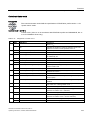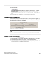
1
SINAMICS G120
Control Units
CU240E
CU240S DP
CU240S PN
Operating Instructions · 03/2009
SINAMICS
Answers for industry.
CU240S
CU240S DP-F
CU240S PN-F
SINAMICS
SINAMICS G120
CU240S and CU240E Control
Units, FW 3.2
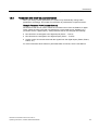
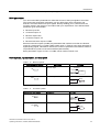
Introduction
1
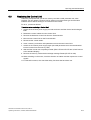
Description
2
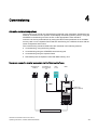
Connection
3
Commissioning
4
Functions
5
Servicing and maintenance
6
Messages and fault codes
7
Technical data
8
Operating Instructions
Edition 03/2009, FW 3.2
03/2009
A5E02440075B AA
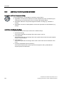
Legal information
Warning notice system
This manual contains notices you have to observe in order to ensure your personal safety, as well as to prevent
damage to property. The notices referring to your personal safety are highlighted in the manual by a safety alert
symbol, notices referring only to property damage have no safety alert symbol. These notices shown below are
graded according to the degree of danger.
DANGER
indicates that death or severe personal injury will result if proper precautions are not taken.
WARNING
indicates that death or severe personal injury may result if proper precautions are not taken.
CAUTION
with a safety alert symbol, indicates that minor personal injury can result if proper precautions are not taken.
CAUTION
without a safety alert symbol, indicates that property damage can result if proper precautions are not taken.
NOTICE
indicates that an unintended result or situation can occur if the corresponding information is not taken into
account.
If more than one degree of danger is present, the warning notice representing the highest degree of danger will
be used. A notice warning of injury to persons with a safety alert symbol may also include a warning relating to
property damage.
Qualified Personnel
The device/system may only be set up and used in conjunction with this documentation. Commissioning and
operation of a device/system may only be performed by qualified personnel. Within the context of the safety notes
in this documentation qualified persons are defined as persons who are authorized to commission, ground and
label devices, systems and circuits in accordance with established safety practices and standards.
Proper use of Siemens products
Note the following:
WARNING
Siemens products may only be used for the applications described in the catalog and in the relevant technical
documentation. If products and components from other manufacturers are used, these must be recommended
or approved by Siemens. Proper transport, storage, installation, assembly, commissioning, operation and
maintenance are required to ensure that the products operate safely and without any problems. The permissible
ambient conditions must be adhered to. The information in the relevant documentation must be observed.
Trademarks
All names identified by ® are registered trademarks of the Siemens AG. The remaining trademarks in this
publication may be trademarks whose use by third parties for their own purposes could violate the rights of the
owner.
Disclaimer of Liability
We have reviewed the contents of this publication to ensure consistency with the hardware and software
described. Since variance cannot be precluded entirely, we cannot guarantee full consistency. However, the
information in this publication is reviewed regularly and any necessary corrections are included in subsequent
editions.
Siemens AG
Industry Sector
Postfach 48 48
90026 NÜRNBERG
GERMANY
A5E02440075B AA
Ⓟ 03/2009
Copyright © Siemens AG 2008.
Technical data subject to change
Table of contents
1
2
3
4
Introduction................................................................................................................................................ 9
1.1
About this manual ..........................................................................................................................9
1.2
Fast track commissioning ............................................................................................................10
1.3
1.3.1
1.3.2
1.3.3
Adapting inverters to the application (parameterization for entry level personnel)......................11
General basics .............................................................................................................................11
Parameter ....................................................................................................................................12
Parameters with follow-on parameterization................................................................................13
1.4
Frequently required parameters...................................................................................................14
1.5
1.5.1
1.5.2
Extended adaptation options (parameterization for advanced level personnel)..........................16
BICO technology: basic principles ...............................................................................................16
BICO technology: example ..........................................................................................................19
Description............................................................................................................................................... 21
2.1
Modularity of the converter system ..............................................................................................21
2.2
Overview of Control Units ............................................................................................................23
2.3
Overview of Power Modules ........................................................................................................24
2.4
Reactors and filters ......................................................................................................................25
Connection .............................................................................................................................................. 27
3.1
Procedure for installing the frequency inverter ............................................................................27
3.2
Mounting reactors and filters........................................................................................................28
3.3
3.3.1
3.3.2
3.3.3
Mounting Power Modules ............................................................................................................30
Dimensions, hole drilling templates, minimum clearances, tightening torques ...........................31
Wiring Power Modules .................................................................................................................36
EMC-compliant connection ..........................................................................................................39
3.4
3.4.1
Installing the Control Unit.............................................................................................................41
Interfaces, connectors, switches, control terminals, LEDs on the CU .........................................42
Commissioning ........................................................................................................................................ 45
4.1
Initial coupling of the CU and PM - message F0395 ...................................................................46
4.2
Restoring the factory settings ......................................................................................................47
4.3
Preparing commissioning.............................................................................................................48
4.4
4.4.1
4.4.2
4.4.3
Commissioning with factory settings............................................................................................51
Wiring examples for the factory settings......................................................................................52
Factory setting of the frequency inverter .....................................................................................54
Default terminal settings ..............................................................................................................56
4.5
4.5.1
4.5.2
4.5.3
4.5.4
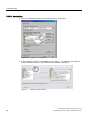
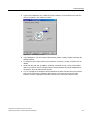
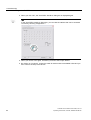
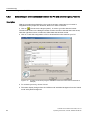
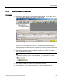
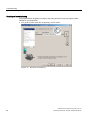
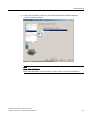
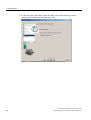
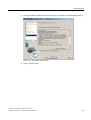
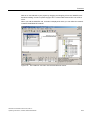
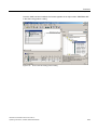
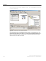
Commissioning with STARTER ...................................................................................................58
Creating a STARTER project.......................................................................................................59
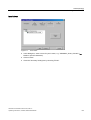
Establishing an online connection between the PC and converter (going "online") ....................64
Starting the general commissioning.............................................................................................65
Commissioning the application ....................................................................................................70
CU240S and CU240E Control Units, FW 3.2
Operating Instructions, 03/2009, A5E02440075B AA
5
Table of contents
5
6
4.6
4.6.1
4.6.2
4.6.3
4.6.4
4.6.5
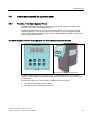
Commissioning with the operator panel...................................................................................... 71
Function of the Basic Operator Panel ......................................................................................... 71
BOP controls and displays .......................................................................................................... 72
Parameterization with the BOP (two examples) ......................................................................... 73
Commissioning steps .................................................................................................................. 74
Commissioning V/f control .......................................................................................................... 74
4.7
4.7.1
4.7.2
Data backup with the operator panel and memory card ............................................................. 77
Saving and transferring data using the BOP............................................................................... 77
Saving and transferring data using the MMC.............................................................................. 78
Functions ................................................................................................................................................. 81
5.1
Overview of inverter functions..................................................................................................... 81
5.2
5.2.1
5.2.2
5.2.3
5.2.4
5.2.5
5.2.6
Inverter control ............................................................................................................................ 84
Frequency inverter control using digital inputs (two/three-wire control) ..................................... 84
Two-wire control, method 1......................................................................................................... 87
Two-wire control, method 2......................................................................................................... 88
Two-wire control, method 3......................................................................................................... 89
Three-wire control, method 1 ...................................................................................................... 90
Three-wire control, method 2 ...................................................................................................... 91
5.3
5.3.1
5.3.2
5.3.3
Command sources ...................................................................................................................... 93
Selecting command sources ....................................................................................................... 93
Assigning functions to digital inputs ............................................................................................ 94
Controlling the motor via the fieldbus.......................................................................................... 95
5.4
5.4.1
5.4.2
5.4.3
5.4.4
5.4.5
5.4.6
Setpoint sources ......................................................................................................................... 96
Selecting frequency setpoint sources ......................................................................................... 96
Using analog inputs as a setpoint source ................................................................................... 97
Using a motorized potentiometer as a setpoint source............................................................... 99
Using the fixed frequency as a setpoint source ........................................................................ 100
Running the motor in jog mode (JOG function) ........................................................................ 101
Specifying the motor speed via the fieldbus ............................................................................. 102
5.5
Changing over the command data sets (manual, automatic) ................................................... 103
5.6
5.6.1
5.6.2
Setpoint preparation.................................................................................................................. 106
Minimum frequency and maximum frequency .......................................................................... 106
Parameterizing the ramp-function generator ............................................................................ 107
5.7
5.7.1
5.7.1.1
5.7.1.2
5.7.1.3
5.7.1.4
5.7.2
5.7.2.1
5.7.2.2
5.7.2.3
5.7.2.4
Closed-loop control ................................................................................................................... 109
V/f control .................................................................................................................................. 109
Typical applications for V/f control ............................................................................................ 109
V/f control with linear characteristic .......................................................................................... 110
V/f control with parabolic characteristic..................................................................................... 111
Additional characteristics for the V/f control.............................................................................. 111
Vector control ............................................................................................................................ 112
Typical applications for vector control....................................................................................... 112
Commissioning vector control ................................................................................................... 113
Torque control ........................................................................................................................... 114
Using a speed encoder ............................................................................................................. 115
5.8
5.8.1
5.8.2
5.8.3
5.8.4
Protection functions................................................................................................................... 118
Overtemperature protection for the frequency inverter and motor............................................ 118
Overcurrent protection .............................................................................................................. 120
Limiting the maximum DC link voltage...................................................................................... 121
Load torque monitoring (system protection) ............................................................................. 122
CU240S and CU240E Control Units, FW 3.2
Operating Instructions, 03/2009, A5E02440075B AA
Table of contents
6
7
5.9
5.9.1
5.9.2
Evaluating the frequency inverter status....................................................................................124
Assigning specific functions to digital outputs............................................................................124
Assigning certain functions to analog outputs ...........................................................................126
5.10
5.10.1
5.10.1.1
5.10.1.2
5.10.1.3
5.10.1.4
5.10.2
5.10.2.1
5.10.2.2
5.10.3
5.10.4
5.10.5
5.10.6
Technological functions .............................................................................................................128
Braking functions of the frequency inverter ...............................................................................128
DC and compound braking ........................................................................................................130
Dynamic braking ........................................................................................................................133
Regenerative braking.................................................................................................................135
Parameterizing a motor holding brake.......................................................................................136
Automatic restart and flying restart ............................................................................................139
Flying restart: switching on the converter when the motor is running........................................139
"Automatic restart" function after power failure..........................................................................141
Technology controller.................................................................................................................145
Positioning down ramp...............................................................................................................146
Logical and arithmetic functions using function blocks ..............................................................147
Changing over drive data sets (several motors connected to a frequency inverter) .................148
5.11
5.11.1
5.11.2
5.11.2.1
5.11.2.2
5.11.2.3
5.11.2.4
5.11.3
5.11.3.1
5.11.3.2
5.11.3.3
5.11.3.4
5.11.3.5
5.11.3.6
Operation in fieldbus systems....................................................................................................151
Communication interfaces .........................................................................................................151
Communication via USS ............................................................................................................151
User data range of the USS message frame.............................................................................154
Data structure of the USS parameter channel...........................................................................154
Timeouts and other errors..........................................................................................................160
USS process data channel (PZD)..............................................................................................160
Communication via PROFIBUS and PROFINET.......................................................................161
Connect the frequency inverter to PROFIBUS ..........................................................................161
Example for configuring the inverter on PROFIBUS..................................................................162
Integrating a frequency inverter in PROFINET ..........................................................................172
Example for configuring the inverter on PROFINET..................................................................173
The PROFIdrive profile ..............................................................................................................176
STEP 7 program examples........................................................................................................188
5.12
5.12.1
5.12.2
5.12.3
5.12.4
5.12.5
5.12.6
5.12.7
5.12.8
5.12.8.1
5.12.8.2
5.12.8.3
Safety functions .........................................................................................................................195
Overview ....................................................................................................................................195
Connecting-up the fail-safe inputs .............................................................................................198
Restoring safety-related parameters to the factory setting........................................................200
Controlling the safety functions via PROFIsafe .........................................................................201
Controlling the safety functions via digital inputs .......................................................................201
Settings for the "STO" function ..................................................................................................204
Settings of the SS1, SLS and SBC safety functions..................................................................206
Acceptance test and report ........................................................................................................208
Documentation of the acceptance test ......................................................................................209
Function check of the acceptance test ......................................................................................210
Filling in the acceptance report ..................................................................................................213
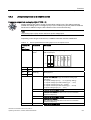
Servicing and maintenance.................................................................................................................... 215
6.1
Behavior of the frequency inverter when replacing components...............................................215
6.2
Replacing the Power Module .....................................................................................................216
6.3
Replacing the Control Unit .........................................................................................................217
6.4
Standard commissioning............................................................................................................218
Messages and fault codes ..................................................................................................................... 219
7.1
Status display using LEDs .........................................................................................................220
7.2
Alarm and error messages.........................................................................................................225
CU240S and CU240E Control Units, FW 3.2
Operating Instructions, 03/2009, A5E02440075B AA
7
Table of contents
8
Technical data ....................................................................................................................................... 227
8.1
Technical data, CU240S Control Unit ....................................................................................... 227
8.2
Technical data, CU240E Control Unit ....................................................................................... 228
8.3
General technical data, PM240 Power Modules....................................................................... 229
8.4
Power-dependent technical data, PM240 Power Modules ....................................................... 230
8.5
General technical data, PM250 Power Modules....................................................................... 233
8.6
Power-dependent technical data, PM250 Power Modules ....................................................... 234
8.7
General technical data, PM260 Power Modules....................................................................... 235
8.8
Power-dependent technical data, PM260 Power Modules ....................................................... 236
Index...................................................................................................................................................... 237
8
CU240S and CU240E Control Units, FW 3.2
Operating Instructions, 03/2009, A5E02440075B AA
1
Introduction
1.1
About this manual
Who requires the operating instructions and why?
These operating instructions primarily address fitters, commissioning engineers and machine
operators. The operating instructions describe the devices and device components and
enable the target groups being addressed to install, connect-up, parameterize, and
commission the inverters safely and in the correct manner.
What is described in the operating instructions?
These operating instructions provide a summary of all of the information required to operate
the inverter under normal, safe conditions.
The information provided in the operating instructions has been compiled in such a way that
it is sufficient for all standard applications and enables drives to be commissioned as
efficiently as possible. Where it appears useful, additional information for entry level
personnel has been added.
The operating instructions also contain information about special applications. Since it is
assumed that readers already have a sound technical knowledge of how to configure and
parameterize these applications, the relevant information is summarized accordingly. This
relates, e.g. to operation with fieldbus systems and safety-related applications.
Additional information on SINAMICS G120
● As download: List Manual
(http://support.automation.siemens.com/WW/view/en/32465038) CU240E and CU240S
Control Units
Among other things, the List manual includes
– A detailed description of all of the parameters
– Function diagrams of all of the inverter functions
– A list of the fault messages and alarms
● As download: All of the operating instructions, manuals on SINAMICS G120
(http://support.automation.siemens.com/WW/view/en/22339653/133300)
● On DVD: SD Manual Collection - all manuals on low-voltage motors, geared motors and
low-voltage inverters, 5 languages.
– MLFB: 6SL3298-0CA00-0MG0 (supplied once)
– MLFB: 6SL3298-0CA10-0MG0 (update service for 1 year; supplied 4 times)
● As download: Catalog D 11.1: SINAMICS G110 / G120 Inverter Chassis Units SINAMICS
G120D Distributed Inverters.
(http://sd.nes.siemens.de/sales_2003/support/info/catalogues/html_76/index.html#Catalo
gs_Inverters)
The catalog includes ordering data as well as engineering and selection data.
CU240S and CU240E Control Units, FW 3.2
Operating Instructions, 03/2009, A5E02440075B AA
9
Introduction
1.2 Fast track commissioning
1.2
Fast track commissioning
Procedure when commissioning
1. Required components
– Power Module, Control Unit; optional: Operator panel or PC connection kit
2. Installing the inverter -> Chapter 3.3 (Page 30)
– Installing the Power Modules (minimum clearances, components) -> Chapter 3.3.1
(Page 31)
– Connecting-up Power Modules (line supply connections, motor circuit (Δ/Y), EMC) ->
Chapter 3.3.2 (Page 36) and Chapter 3.3.3 (Page 39)
– Installing and connecting up the Control Unit (control terminals, user interfaces) ->
Chapter 3.4.1 (Page 42)
3. Switching-on the line supply voltage and 24 V control voltage
4. Preparing commissioning
– Information and data that you should obtain before commissioning -> Chapter 4.3
(Page 48)
– If the components are not brand new, but are used: Restoring the factory settings ->
Chapter 4.2 (Page 47)
5. Quick commissioning
– When using the factory settings -> Chapter 4.4 (Page 51)
– With STARTER (commissioning tool) -> Chapter 4.5 (Page 58)
– With BOP (Basic Operator Panel)-> Chapter 4.6 (Page 71)
6. Storing data in a power-independent manner -> Chapter 4.7 (Page 77)
7. You can now switch-on the motor.
Finely adjusting the inverter
With the commissioning procedure described above, your inverter is supplied with the basic
functions and settings that are completely adequate for many applications.
Using the functions and parameters described in Chapter 5 (Page 81), if required, you can
precisely adapt this closed-loop control structure of your inverter to your application.
10
CU240S and CU240E Control Units, FW 3.2
Operating Instructions, 03/2009, A5E02440075B AA
Introduction
1.3 Adapting inverters to the application (parameterization for entry level personnel)
1.3
Adapting inverters to the application (parameterization for entry level
personnel)
1.3.1
General basics
Parameterizable inverters transform standard motors into variable-speed drives
Inverters are parameterized to adapt them to the motor being driven so that this can be
optimally operated and protected. This is realized using one of the following operator units:
● Keyboard and display unit (Operator Panel) that is snapped onto the inverter.
● Software (STARTER commissioning tool) that allows the inverter to be parameterized
and controlled from a PC.
Inverters are especially used to improve and expand the starting and speed response of
motors.
Many standard applications can function with the default parameters
Although inverters can be parameterized for very specific applications, many standard
applications can be configured by means of just a few parameters.
Use the factory settings (where possible)
For basic applications, commissioning can be carried out using just the factory settings (see
Section "Commissioning with factory settings" (Page 51)).
Use quick commissioning (for simple, standard applications)
In the majority of standard applications, commissioning can be carried out by entering or
changing just a few parameters during quick commissioning (see Section "Commissioning
with Operator Panel" (Page 71)).
CU240S and CU240E Control Units, FW 3.2
Operating Instructions, 03/2009, A5E02440075B AA
11
Introduction
1.3 Adapting inverters to the application (parameterization for entry level personnel)
1.3.2
Parameter
Parameter types
There are two types of parameters, adjustable and display parameters.
Adjustable parameters
Adjustable parameters are represented with four digits preceded by the letter "P". You can
change the value of these parameters within a defined range.
Example:
P0305 is the parameter for the rated motor current in Amps. This parameter is set during
commissioning. You can enter values between 0.01 and 10000.
Display parameters
Display parameters are represented with four digits preceded by the letter "r". You cannot
change the value of these parameters.
Example:
r0027 is the parameter for the inverter output current. The inverter measures the current and
writes the current value to the parameter. You can display the parameter value, e.g. using an
analog output of the inverter.
Change protection for write parameters
The process of changing parameter values is subject to certain conditions. If an attempt to
change a parameter is rejected by the inverter, this can have a number of causes:
1. The inverter operating state does not allow you to change parameters.
For example, certain parameters can only be changed when the inverter is in
commissioning mode.
2. In some cases, you may not be able to change certain parameters due to automatic
follow-on parameterization.
Example: When P0701 = 1, the ON/OFF1 command is connected to digital input 0. As
follow-on parameterization, P0840 (source of the ON/OFF1 command) is assigned value
722.0 (status of digital input 0). which means that P0840 can no longer be changed.
3. Parameter protection via P0927 has been activated.
Example: P0927 = 1101 prevents parameters from being changed from the BOP.
For each parameter, the List Manual specifies whether and which conditions apply for
changing the values.
12
CU240S and CU240E Control Units, FW 3.2
Operating Instructions, 03/2009, A5E02440075B AA
Introduction
1.3 Adapting inverters to the application (parameterization for entry level personnel)
1.3.3
Parameters with follow-on parameterization
When you change certain parameters, the system may automatically change other
parameters accordingly. This makes it much easier to parameterize complex functions.
Example: Parameter P0700 (command source)
Parameter P0700 can be used to switch the command source from the fieldbus to digital
inputs. When the value of P0700 is changed from 6 (command source "fieldbus") to 2
(command source "digital inputs"), other parameter values are changed automatically:
● New functions are assigned to the digital inputs (P0701 ... P0713)
● New functions are assigned to the digital outputs (P0731 ... P0733)
● Inverter control is interconnected with the signals from the digital inputs (P0800, P0801,
P0840, etc.)
For more information about follow-on parameterization for P0700, see the List Manual.
CU240S and CU240E Control Units, FW 3.2
Operating Instructions, 03/2009, A5E02440075B AA
13
Introduction
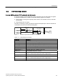
1.4 Frequently required parameters
1.4
Frequently required parameters
Parameters that in many cases help
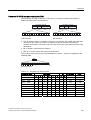
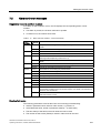
Table 1- 1
This is how you filter the parameter list to keep the number of displayed parameters transparent
Parameter
Description
P0003 =
User access level
1: Standard: Allows access to the most frequently used parameters (factory setting)
2: Extended: Extended access, e.g. to inverter I/O functions
3: Expert: To be used by experts
P0004 =
Parameter filter
0: All the parameters are displayed (factory setting).
2: Inverter
3: Motor - data of the motor and output filter are displayed
4: Speed encoder - parameters for the optional speed encoder are displayed
Table 1- 2
How to switch to commissioning mode or restore the factory setting
Parameter
Description
P0010 =
Commissioning parameters
0: Ready (factory setting)
1: Perform quick commissioning
30: Factory setting - initiate restore factory settings
Table 1- 3
How to determine the firmware version of the Control Unit
Parameter
Description
r0018
The firmware version is displayed:
Table 1- 4
Parameter
This is how you reset the parameters to the factory setting
Description
P0010 = 30
30: Factory setting - initiate restore factory settings
P0970 = 1
1: Resetting - restoring all parameters to the factory setting
(Exception: Password-protected parameters of the safety functions are not reset!)
Table 1- 5
This is how you select the command source of the control signals (ON/OFF, reversing) of the inverter
Parameter
Description
P0700 =
0: Factory default setting
1: Operator Panel
2: Digital inputs (P0701 … P0709); factory setting non-fieldbus-capable inverters
4: USS on RS 232
5: USS on RS 485 (not available for CU240S DP or CU240S DP-F)
6: Fieldbus (P2050 … P02091); (factory setting for fieldbus-capable inverters)
14
CU240S and CU240E Control Units, FW 3.2
Operating Instructions, 03/2009, A5E02440075B AA
Introduction
1.4 Frequently required parameters
Table 1- 6
This is how you select the setpoint source for the frequency
Parameters
Description
P1000 =
0: No main setpoint
1: MOP setpoint
2: Analog setpoint (factory setting for non-fieldbus-capable inverters)
3: Fixed frequency
4: USS at RS 232
5: USS on RS 485
6: Fieldbus (factory setting for fieldbus-capable inverters)
7: Analog setpoint 2
Table 1- 7
This is how you parameterize the up and down ramps
Parameters
Description
P1080 = …
Minimum frequency
0.00 [Hz] factory setting
P1082 = …
Maximum frequency
50.00 [Hz] factory setting
P1120 = …
Rampup time
10.00 [s]
P1121 = …
Rampdown time
10.00 [s]
Table 1- 8
This is how you set the closed-loop type
Parameters
Description
P1300 = 2
Extended access
P1300 = ...
0: V/f control with linear characteristic (factory setting)
1: V/f control with FCC
2: V/f control with parabolic characteristic
3: V/f control with programmable characteristic
20: Sensorless vector control
21: Vector control with encoder
22: Torque vector control without encoder
Table 1- 9
This is how you optimize the starting behavior of the V/f control for a high break loose torque and overload
Parameters
Description
P0003 = 2
Extended access
P1310 = …
Voltage boost to compensate resistive losses
The voltage boost is effective from standstill up to the rated speed.
The voltage boost continually decreases with increasing speed.
The maximum voltage boost is effective at speed zero and is in V:
Rated motor current (P305) × stator resistance (P350) × P1310 /100.
P1311 = …
Voltage when accelerating
The voltage boost is effective from standstill up to the rated speed.
The voltage boost is independent of the speed.
The voltage boost in V is:
Rated motor current (P305) × stator resistance (P350) × P1311 /100
CU240S and CU240E Control Units, FW 3.2
Operating Instructions, 03/2009, A5E02440075B AA
15
Introduction
1.5 Extended adaptation options (parameterization for advanced level personnel)
1.5
Extended adaptation options (parameterization for advanced level
personnel)
1.5.1
BICO technology: basic principles
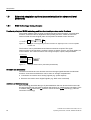
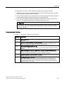
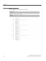
Functional principle of BICO technology and inverter closed/open-loop control functions
The inverter software offers a range of open/closed-loop control functions, communication
functions, as well as various diagnostics and operating functions. These functions are
interconnected via internal signal paths and represent the default control structure.
P0840
DI 0
r0722.0
Terminal 5
Figure 1-1
ON/
OFF1
Example: Pre-assigned signal interconnection for digital input 0 of a non-bus-capable
Control Unit
The functions can be parameterized and interconnected as required. The signal
interconnection of the functions is realized, contrary to electric circuitry, not using cables, but
in the software. The various functions use a range of inputs, outputs, and parameters.
Enable MOP (raise)
P1035.CDS
(19.13)
MOP
Enable MOP (lower)
P1036.CDS
(19.14)
Figure 1-2
MOP output freq [Hz]
r1050
Example: MOP function (motorized potentiometer)
Binectors and connectors
Connectors and binectors are elements used to exchange signals between the individual
functions. Connectors and binectors can be seen as "storage compartments":
● Connectors are used to store "analog" signals (e.g. speed setpoint)
● Binectors are used to store "digital" signals (e.g. 'MOP raise' command)
Definition of BICO technology
BICO technology describes the type of parameterization that can be used to disconnect all
the internal signal interconnections between the functions or establish new connections. This
is realized using Binectors and Connectors. Hence the name BICO technology. ( Binector
Connector Technology)
16
CU240S and CU240E Control Units, FW 3.2
Operating Instructions, 03/2009, A5E02440075B AA
Introduction
1.5 Extended adaptation options (parameterization for advanced level personnel)
BICO parameters
You can use the BICO parameters to define the sources of the input signals of a function.
This means that using BICO parameters you can define from which connectors and
binectors a function reads-in its input signals. thereby enabling you to "interconnect" the
functions stored in the devices in accordance with your requirements. Four different BICO
parameter types are available:
● Binector inputs: BI
● Connector inputs: CI
● Binector outputs: BO
● Connector outputs: CO
● Binector/connector outputs: CO/BO
Binector/connector outputs (CO/BO) are parameters that combine more than one binector
output in a single word (e.g. r0052 CO/BO: status word 1). Each bit in the word represents a
digital (binary) signal. This feature reduces the number of parameters and makes it easier to
set parameters by means of the serial interface (data transfer).
BICO parameters of type CO, BO, or CO/BO can be used more than once.
BICO symbols, representation, and description
Table 1- 10
Binector symbols
Abbreviation and symbol
BI
Description
Function
Binector input
'DWDIORZ
3[[[[
)XQFWLRQ
%,
BO
Binector output
'DWDIORZ
U[[[[
)XQFWLRQ
%2
Table 1- 11
Connector symbols
Abbreviation and symbol
CI
Description
Connector input
Function
'DWDIORZ
3[[[[
)XQFWLRQ
&,
CO
Connector output
'DWDIORZ
)XQFWLRQ
U[[[[
&2
CU240S and CU240E Control Units, FW 3.2
Operating Instructions, 03/2009, A5E02440075B AA
17
Introduction
1.5 Extended adaptation options (parameterization for advanced level personnel)
Table 1- 12
Connector and binector output symbols
Abbreviation and symbol
&2%2
Description
Function
Binector/connector output
'DWDIORZ
U[[[[
)XQFWLRQV
&2%2
When do you need to use BICO technology?
BICO technology allows you to adapt the inverter to a wide range of different requirements.
This does not necessarily have to involve highly complex functions.
Example 1: Assign a different function to a digital input.
Example 2: Switch over the speed setpoint from the fixed frequency to the analog input.
What precautions should you take when using BICO technology?
Always apply caution when handling internal interconnections. Note which changes you
make as you go along since the process of analyzing them later can be quite difficult.
The STARTER commissioning tool offers various screens that make it much easier for you
to use BICO technology. The signals that you can interconnect are displayed in plain text,
which means that you do not need any prior knowledge of BICO technology.
What sources of information do you need to help you set parameters using BICO
technology?
● This manual is sufficient for simple signal interconnections, e.g. assigning a different
significance to the to digital inputs.
● The parameter list in the List Manual is sufficient for signal interconnections that go
beyond just simple ones.
● You can also refer to the function diagrams in the List Manual for complex signal
interconnections.
18
CU240S and CU240E Control Units, FW 3.2
Operating Instructions, 03/2009, A5E02440075B AA
Introduction
1.5 Extended adaptation options (parameterization for advanced level personnel)
1.5.2
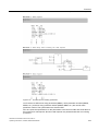
BICO technology: example
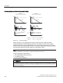
Example: Shifting a basic PLC functionality into the inverter
A conveyor system is to be configured in such a way that it can only start when two signals
are present simultaneously. These could be the following signals, for example:
● The oil pump is running (the required pressure level is not reached, however, until after
five seconds)
● The protective door is closed
The task is realized by inserting free blocks between the digital input 0 and the internal ON
command for the motor and interconnecting them.
P2850 = 5,0 [s]
P2800 P2801[0]
DI 0
P2849
Index [0]
r0722.0
T
0
r2852
Timer
DI 1
r0722.1
P2810
Index [0]
Index [1]
&
Figure 1-3
Example: Signal interconnection for interlock
Table 1- 13
Parameterizing an interlock
r2811
P0840
Index [0]
ON/
OFF1
Parameter
Description
P0003 = 3
Enable expert access to parameters
P0700 = 2
Select the command source: Digital inputs
P0701 (e.g.) = 99
Enable/"open" digital input 0 (DI0) for BICO parameterization
P0702 (e.g.) = 99
Enable/"open" digital input 1 (DI1) for BICO parameterization
P2800 = 1
Group enable all freely-programmable function blocks (FFB)
P2801 [In000] = 1
Individual enable of the AND function block
P2802 [In000] = 1
Individual enable of the TIMER function block
P2850 = 5.0
Set the TIMER delay time: 5 seconds
P2849 = r0722.0
Connect the status of DI0 to the TIMER input
r0722.0 = Parameter that displays the status of digital input 0.
P2810 [In000] = r2852
Connect the TIMER output to the 1st input of the AND
P2810 [In001] = r0722.1
Connect the status of DI1 to the 2nd AND input
r0722.1 = Parameter that displays the status of digital input 1.
P0840 = r2811
CU240S and CU240E Control Units, FW 3.2
Operating Instructions, 03/2009, A5E02440075B AA
Connect the AND output to the control command ON/OFF1
19
Introduction
1.5 Extended adaptation options (parameterization for advanced level personnel)
Explanations of the example
Open the default signal interconnection for BICO parameterization
The default setting P0701 = 1 indicates the following internal signal interconnection:
P0840
DI 0
ON/
OFF1
r0722.0
Terminal 5
Figure 1-4
Default parameterization
The setting P0701 = 99 means that a pre-assigned signal interconnection is disconnected
and therefore the connection opened for BICO parameterization.
P0840
DI 0
r0722.0
Terminal 5
Figure 1-5
ON/
OFF1
BICO parameterization
When P0701 = 99, the binector input of the ON/OFF1 function (P0840) is available for
activation by a signal source other than r0722.0 (in this case r2852).
DI 0
r0722.0
P2849
Index [0]
T
0
r2852
Timer
Figure 1-6
P2810
Index [0]
Index [1]
&
P0840
r2811
ON/
OFF1
Interconnection after insertion of two functions
Principle of connecting functions by means of BICO technology
A connection between two functions comprises a connector/binector and a BICO parameter.
Connections are always established with respect to the input of a particular function, which
means that the output of an upstream function must always be assigned to the input of a
downstream function. The assignment is always made by entering the number of the
connector/binector from which the required input signals are read in a BICO parameter.
With this functional logic in mind, where does the signal come from?
20
CU240S and CU240E Control Units, FW 3.2
Operating Instructions, 03/2009, A5E02440075B AA
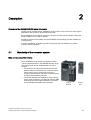
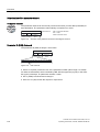
2
Description
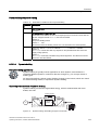
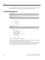
Overview of the SINAMICS G120 family of inverters
Thanks to their modular design, SINAMICS G120 inverters can be used in a wide range of
applications with respect to functionality and power.
Each SINAMICS G120 inverter comprises a Control Unit and a Power Module. The power
range extends from 0.37 kW to 250 kW.
The Basic Operator Panel (BOP) and the STARTER commissioning tool are available for
commissioning.
A range of additional, application-specific components are also available (e.g. filters,
reactors, braking resistors).
2.1
Modularity of the converter system
Main components of the inverter
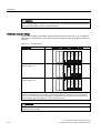
Each SINAMICS G120 inverter comprises a Control
Unit and Power Module. In the SINAMICS G120 range,
the Control Units can be combined with any Power
Module.
• The Control Unit controls and monitors the Power
Module and the connected motor in various control
modes (which can be selected as required). It
supports communication with local or central control
as well as with monitoring devices.
• The Power Modules are available for motors with a
power range of between 0.37 kW and 250 kW. IGBT
technology and pulse-width modulation are used to
ensure reliable and flexible motor operation.
CU240S and CU240E Control Units, FW 3.2
Operating Instructions, 03/2009, A5E02440075B AA
Power
Module
Control
Unit
21
Description
2.1 Modularity of the converter system
Supplementary components
In addition to the main components, the following components are available for
commissioning and parameterization:
Operator Panel (OP) for parameterization,
diagnostics, and control as well as for copying drive
parameters.
MMC memory card for carrying out standard
commissioning of more than one inverter and for
external data backup.
PC connection kit and STARTER commissioning
tool for prompted, PC-based commissioning.
Filters and reactors
• Line filters (classes A and B)
• Line reactors
• Braking resistors
• Output reactors
• Sine-wave filter
Further options
• Brake Relay
• Safe Brake Relay
• Adapter for DIN rail mounting
• Shield connection kit
22
CU240S and CU240E Control Units, FW 3.2
Operating Instructions, 03/2009, A5E02440075B AA
Description
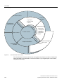
2.2 Overview of Control Units
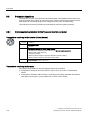
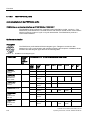
2.2
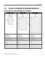
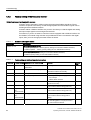
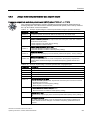
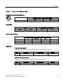
Overview of Control Units
&RQWURO8QLWVZLWKVDIHW\
UHOHYDQWIXQFWLRQV
&RQWURO8QLWVZLWKILHOGEXVLQWHUIDFH
&8(
&RVWHIIHFWLYH
YDULDQWV
)XQFWLRQDOO\
LGHQWLFDOZLWKWKH
&86
KRZHYHUQR
HQFRGHUFRQQHF
WLRQIHZHU,2V
Figure 2-1
&86
&RQWURO8QLW
&86
IRURSHUDWLRQYLD
WHUPLQDOVDQG
866YLD56
&86
'3
&RQWURO8QLW
&86
DGGLWLRQDOO\ZLWK
352),%86'3
LQWHUIDFH
&86
31
&RQWURO8QLW
&86
DGGLWLRQDOO\ZLWK
352),1(7
LQWHUIDFH
&86
'3)
&RQWURO8QLW
&86
DGGLWLRQDOO\ZLWK
352),%86'3
LQWHUIDFHDQG
VDIHW\UHOHYDQW
IXQFWLRQVYLD
WHUPLQDOVRU
352),VDIH
&86
31)
&RQWURO8QLW
&86
DGGLWLRQDOO\ZLWK
352),1(7
LQWHUIDFHDQG
VDIHW\UHOHYDQW
IXQFWLRQVYLD
WHUPLQDOVRU
352),VDIH
Control Unit variants
CU240S and CU240E Control Units, FW 3.2
Operating Instructions, 03/2009, A5E02440075B AA
23
Description
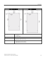
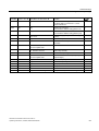
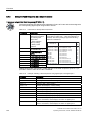
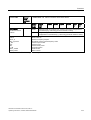
2.3 Overview of Power Modules
2.3
Overview of Power Modules
Figure 2-2
Power Module versions
A number of Power Module versions are available for different line supply voltages in a
power range from between 0.37 kW and 250 kW. Depending on the Power Module used, the
energy released in regenerative mode is either
● fed back to the supply system (Efficient Infeed Technology) or
● stored in the DC link and/or fed to an external braking resistor.
Overview of the available Power Modules
Depending on the output, Power Modules are available with different frame sizes The range
of frame sizes extends from FSA to FSGX.
FSA
PM240
3-ph. 400V
AC
0.37 kW … 2.2 kW …
1.5 kW
4kW
FSD
FSE
7.5 kW …
15 kW
18.5 kW … 37 kW …
30 kW
45 kW
FSF
FSGX
55 kW …
132 kW
160 kW …
250 kW
○
●
●
●
●
◑1)
◑2)
With integr.
Braking chopper
●
●
●
●
●
●
◑2)
-
-
7.5 kW …
15 kW
18.5 kW- 3
0 kW
37 kW …
45 kW
55 kW …
90 kW
With integr. Line
filter, class A
●
●
●
●
Capable of
energy recovery
●
●
●
●
PM260
3-ph. 690V
AC
FSC
With integr. Line
filter, class A
PM250
3-ph. 400V
AC
FSB
-
-
-
11 kW …
18.5 kW
-
30 kW …
55 kW
With/without
integr. Line filter,
Class A
●
●
With integr.
Sine-wave filter
●
●
Capable of
energy recovery
●
●
-
-
● = Feature available; ○ = Feature not available; ◑ = Feature available, modified;
1) PM240 Power Modules, 110 kW and higher, are only available without an integrated class A filter. Instead, an optional
class A line filter for side mounting is available.
2) PM240 FSGX Power Module is only available without integrated components. Instead, optional line reactor, line filter,
output reactor, sine-wave filter, braking chopper, braking resistor and Brake Relay are available.
24
CU240S and CU240E Control Units, FW 3.2
Operating Instructions, 03/2009, A5E02440075B AA
Description
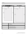
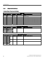
2.4 Reactors and filters
2.4
Reactors and filters
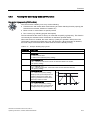
Overview
Depending on the Power Module, the following combinations with filters and reactors are
permitted:
Power Module
Line-side components
Line reactor
PM240
Line filters
class B
●
●
Load-side components
Braking
resistor
Sine-wave filter
●
Output reactor
●
●
PM250
-
●
-
●
●
PM260
-
●
-
integrated
-
CU240S and CU240E Control Units, FW 3.2
Operating Instructions, 03/2009, A5E02440075B AA
25
3
Connection
3.1
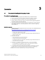
Procedure for installing the frequency inverter
Prerequisites for installing the inverter
Check that the following prerequisites are fulfilled before you install the inverter:
● Are the components, tools and small parts required for installation available?
● Are the ambient conditions permissible? See: Technical data (Page 227)
● Have the cables and wires been routed in accordance with the applicable regulations?
See: EMC-compliant connection (Page 39)
● Are the minimum distances from other equipment complied with? (Cooling sufficient?)
See: Chapter: Dimensions, hole drilling templates, minimum clearances, tightening
torques (Page 31)
Installation sequence
1. Install the Power Module (detailed instructions are provided in the Installation Manual for
the Power Modules
(http://support.automation.siemens.com/WW/view/en/30563173/133300))
– Remove the terminal covers - where applicable
– Connect motor cable and power cable
– Terminate the shield over a large area, if necessary using a shield connection set
– Refit the terminal covers
2. Mount the Control Unit
– Open the terminal covers of the Control Unit
– Connect the control lines to the terminals
– Terminate the shield over a large area, if necessary using a shield connection set
– Close the terminal covers again
3. Control Unit – for operation in a higher-level control – connect to the fieldbus
– For PROFIBUS DP and CANopen connect it via the 9-pin sub D connector
– For RS 485, connect it via the two-part bus connector
4. To commission the drive unit, either plug-in the operator control/display instrument
(operator panel) or connect the inverter to the PC using the PC connection kit.
Installation has now been completed and you can begin commissioning.
CU240S and CU240E Control Units, FW 3.2
Operating Instructions, 03/2009, A5E02440075B AA
27
Connection
3.2 Mounting reactors and filters
3.2
Mounting reactors and filters
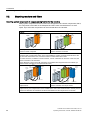
Mounting system components in a space-saving fashion for the inverters
Many system components for the inverters are designed as sub-chassis components, that is,
the component is mounted on the baseplate and the inverter mounted above it to save
space. Up to two base components can be mounted above one another.
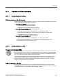
PM240
Power supply
Line
reactor
Power
module
Line
reactor
Line
filter
G_D211_EN_00079a
G_D211_EN_00078a
Power
module
Power supply
Basic layout of a PM240 Power Module with line
reactor as base component
PM240 Power Module frame size FSA with line
reactor and class A line filter
The line-side reactors are equipped with terminals while the reactors on the Power Module side are
equipped with a prefabricated cable. In the final installation position, the mains terminals are at the
top on frame sizes FSA to FSC, and at the bottom on frame sizes FSD to FSE.
For frame size FSA, in addition to the line reactor, a class A line filter can be used. In this case, the
mains connection is at the bottom.
Power Modules of frame size FSB and higher are available with integrated class A line filters (an
external class A line filter is not required in this case).
G_D011_EN_00185
Power
module
Line
reactor
Output
reactor
Power
module
Output
reactor
Line
filter
G_D011_EN_00186
Power
supply
Line
reactor
to the motor
Power
supply
PM240: frame size FSA with line reactor and
output reactor
to the motor
PM240 Power Modules: frame size FSA with line
reactor, line filter, and output reactor
In installations containing more than two base-type system components (e.g. line filter + line reactor +
output reactor), the components must be installed to the side of the Power Modules. whereby the line
reactor and line filter are installed under the Power Module and the output reactor to the side.
28
CU240S and CU240E Control Units, FW 3.2
Operating Instructions, 03/2009, A5E02440075B AA
Connection
3.2 Mounting reactors and filters
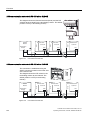
PM250
G_D211_EN_00107a
Power
module
Line
filter
Power
module
Line
filter
Output
reactor
G_D211_EN_00108a
Power
supply
Power supply
to the motor
Basic layout of a PM250 Power Module with class Basic layout of a PM250 Power Module with a
B line filter as a base component
class B line filter as a base component
CU240S and CU240E Control Units, FW 3.2
Operating Instructions, 03/2009, A5E02440075B AA
29
Connection
3.3 Mounting Power Modules
3.3
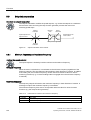
Mounting Power Modules
Options for installing the Power Module
Depending on the format, various options are available for installing inverters. This manual
describes how to install inverters directly on the cabinet wall.
Installation options
Frame size
A
B
C
D
E
F
GX
Installation on standard rails
X
X
X
---
---
---
---
Mounting on a cabinet panel with shield connection kit
X
X
X
X
X
X
---
Installation directly on the cabinet wall
X
X
X
X
X
X
X
Installing Power Modules
Choose the best installation option for your application and install the Power Module in
accordance with the instructions provided in this section.
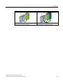
NOTICE
Information about installation
The Power Module must not be installed horizontally.
&RUUHFW
,QFRUUHFW
Devices that could impede the flow of cooling air must not be installed in this area. Make
sure that the ventilation openings for the cooling air for the inverter are not covered and that
the flow of cooling air is not obstructed.
Installing additional components
Depending on the application, additional line reactors, filters, braking resistors, brake relays
etc., may also be used.
Please observe the mounting and installation instructions supplied with these components!
30
CU240S and CU240E Control Units, FW 3.2
Operating Instructions, 03/2009, A5E02440075B AA
Connection
3.3 Mounting Power Modules
3.3.1
Dimensions, hole drilling templates, minimum clearances, tightening torques
Overview of dimensions and hole drilling templates for the Power Modules
0.37 kW … 1.5 kW
2,2 kW … 4 kW
7,5 kW … 15 kW
Retaining type
• 2 x M4 bolts
• 2 x M4 nuts
• 2 x M4 washers
Retaining type
• 4 x M4 bolts
• 4 x M4 nuts
• 4 x M4 washers
Retaining type
• 4 x M5 bolts
• 4 x M5 nuts
• 4 x M5 washers
Tightening torques
• 2.5 Nm (22.1 lbf.in)
Tightening torques
• 2.5 Nm (22.1 lbf.in)
Tightening torques
• 2.5 Nm (22.1 lbf.in)
Distances from other devices
• Lateral: 0 mm (0 inch) up to 40°C
30 mm (1.18 inch) from 40°C and
higher
• Top/bottom: 100 mm (3.93 inch)
Clearances to other devices
• Lateral: 0 mm (0 inch) up to 40°C
40 mm (1.57 inch) from 40°C and
higher
• Top/bottom: 100 mm (3.93 inch)
Clearances to other devices
• Lateral: 0 mm (0 inch) up to 40°C
50 mm (1.96 inch) from 40°C and
higher
• Top/bottom: 125 mm (4.92 inch)
Depth
• Standalone: 145 mm (5.71 inch)
• With CU240E: 187 mm (7.36 inch)
• With CU240S: 208 mm (8.19 inch)
Depth
• Standalone: 165 mm (6.50 inch)
• With CU240E: 207 mm (8.15 inch)
• With CU240S: 228 mm (8.98 inch)
Depth
• Standalone: 185 mm (7.28 inch)
• With CU240E: 227 mm (8.94 inch)
• With CU240S: 248 mm (9.76 inch)
CU240S and CU240E Control Units, FW 3.2
Operating Instructions, 03/2009, A5E02440075B AA
31
Connection
3.3 Mounting Power Modules
18.5 kW … 30 kW without filter
18.5 kW … 30 kW with filter for PM240 and PM250
11 kW … 18 kW for PM260
Retaining type
•
•
•
4 x M6 bolts
4 x M6 nuts
4 x M6 washers
Tightening torques
•
6 Nm (53 lbf.in)
Clearances to other devices
•
•
Lateral: 0 mm (0 inch)
Top/bottom: 300 mm (11.81 inch)
Depth
•
•
•
Standalone: 204 mm (8.03 inch)
With CU240E: 246 mm (9.68 inch)
With CU240S: 267 mm (10.51 inch)
32
CU240S and CU240E Control Units, FW 3.2
Operating Instructions, 03/2009, A5E02440075B AA
Connection
3.3 Mounting Power Modules
37 kW … 45 kW without filter
Retaining type
•
•
•
4 x M6 bolts
4 x M6 nuts
4 x M6 washers
Tightening torques
•
6 Nm (53 lbf.in)
Clearances to other devices
•
•
Lateral: 0 mm (0 inch)
Top/bottom: 300 mm (11.81 inch)
Depth
•
•
•
Standalone: 204 mm (8.03 inch)
With CU240E: 246 mm (9.68 inch)
With CU240S: 267 mm (10.51 inch)
CU240S and CU240E Control Units, FW 3.2
Operating Instructions, 03/2009, A5E02440075B AA
37 kW … 45 kW with filter
33
Connection
3.3 Mounting Power Modules
55 kW … 132 kW without filter for PM240 and PM250
30 kW … 55 kW for PM260
Retaining type
•
•
•
4 x M8 bolts
4 x M8 nuts
4 x M8 washers
Tightening torques
•
13 Nm (115 lbf.in)
Clearances to other devices
•
•
Lateral: 0 mm (0 inch)
Top/bottom: 350 mm (13.77 inch)
Depth
•
•
•
Standalone: 316 mm (12.44 inch)
With CU240E: 358 mm (14.09 inch)
With CU240S: 379 mm (14.92 inch)
34
55 kW … 90 kW with filter
CU240S and CU240E Control Units, FW 3.2
Operating Instructions, 03/2009, A5E02440075B AA
Connection
3.3 Mounting Power Modules
160 kW … 250 kW for PM240
PP
PP
PP
PP PP
PP
PP
PP
Retaining type
•
•
•
6 x M8 bolts
6 x M8 nuts
6 x M8 washers
Tightening torques
•
13 Nm (115 lbf.in)
Clearances to other devices
•
•
•
Lateral: 0 mm (0 inch)
Top: 250 mm (9.84 inch)
Bottom: 150 mm (5.91 inch)
Depth
•
544 mm (21.4 inch)
CU240S and CU240E Control Units, FW 3.2
Operating Instructions, 03/2009, A5E02440075B AA
35
Connection
3.3 Mounting Power Modules
3.3.2
Wiring Power Modules
Prerequisites
Once the Power Module has been properly installed, the line and motor connections can
now be established. The following warning information must be observed here.
WARNING
Line and motor connections
The inverter must be grounded on the supply and motor side. If this is not carried out
properly, this can lead to extremely hazardous conditions which, under certain
circumstances, can result in death.
The device must be disconnected from the electrical power supply before any connections
with the device are established or in any way altered.
The inverter terminals can carry hazardous voltages even after the inverter has been
switched off. After disconnecting the line supply, wait at least 5 minutes until the drive unit
has discharged itself. Only then, carry out any installation and mounting work.
When connecting the inverter to the line supply, ensure that the motor terminal box is
closed.
Even if the LEDs or other indicators do not light up or remain inactive when a function is
switched from ON to OFF, this does not necessarily mean that the unit has been switched
off or is de-energized.
The short-circuit ratio of the power supply must be at least 100.
Make sure that the inverter is configured for the correct supply voltage (the inverter must
not be connected to a higher supply voltage).
If a residual-current circuit breaker is installed on the supply side of the electronic devices
to protect against direct or indirect contact, only type B is permissible. In all other cases,
other protective measures must be implemented, such as creating a barrier between the
electronic devices and the environment by means of double or reinforced insulation, or
disconnecting them from the supply by means of a transformer.
CAUTION
Supply and control cables
The control cables must be laid separately from the supply cables to ensure that the system
is not affected by inductive or capacitive interference.
Note
Electrical protective equipment
Make sure that suitable circuit breakers and/or fuses (with the prescribed rated currents) are
installed between the supply system and inverter (see the technical specifications).
36
CU240S and CU240E Control Units, FW 3.2
Operating Instructions, 03/2009, A5E02440075B AA
Connection
3.3 Mounting Power Modules
Connection example: Power Module PM240
/
/
/
3(
&RQWURO8QLW
)XVHV
89:
///
3RZHU0RGXOH
%UDNH
5HOD\
&RQQHFWRUV
'&
89: 35 5 '&1
%UDNLQJ
UHVLVWRU
3(
%UDNH
5HOD\
0
a
'&9
$&9
Figure 3-1
Connection diagram: PM240 Power Module with Brake Relay
Star connection and delta connection
With SIEMENS motors, you will see a
diagram of both connection types on
the inside of the terminal board cover:
• Star connection (Y)
• Delta connection (Δ)
The motor rating plate provides
information about the correct
connection data:
e.g.: 230/400V Δ/Y means that for a
400V line supply, the motor is
connected up in the Y connection.
CU240S and CU240E Control Units, FW 3.2
Operating Instructions, 03/2009, A5E02440075B AA
'HOWDFRQQHFWLRQ
:
8
9
8
9
:
6WDUFRQQHFWLRQ
:
8
9
8
9
:
8
8
9
:
9
:
37
Connection
3.3 Mounting Power Modules
Connecting-up Power Modules
Line supply connection
Connect the line supply to terminals
U1/L1, V1/L2 and W1/L3.
Motor connection
Connect the braking resistor
Connect the motor at terminals U2, V2,
and W2.
A braking resistor can be connecting at
terminals DCP/R1 and R2.
Connect the protective conductor of the Connect the protective conductor of the Do not ground the braking resistor at
motor to the terminal
line supply to terminal PE of the
of the inverter. the inverter, but directly at your
grounding bar.
inverter.
The following cable lengths are
Power Modules without an integrated
permissible:
line filter can be connected to grounded • Unshielded
(TN, TT) and non-grounded (IT) line
100 m
supply systems. Power Modules with
• Shielded,
an integrated class A line filter are only
50 m for inverters without filter
suitable for TN supply systems.
25 m for inverters with filter
Additional information is provided in
Catalog D11.1 for longer cable lengths
L
U1
L1
N
V1
L2
W1
L3
U2
V2
DCP
R1
W2 R2
PE
FSA
FSB
FSC
FSD
FSE
FSF
FSGX
Power
0.37 kW …
1.5 kW
2.2 kW …
4 kW
7.5 kW …
15 kW
18.5 kW …
30 kW
37 kW …
45 kW
55 kW …
132 kW
160 kW …
250 kW
Connection
cross-section
1 mm² …
2.5 mm²
1.5 mm² …
6 mm²
4 mm² …
10 mm²
10 mm² …
35 mm²
10 mm² …
35 mm²
35 mm² …
120 mm²
95 mm² …
2 x 240 mm²
Torque
1.1 Nm
1.5 Nm
2.25 Nm
6 Nm
6 Nm
13 Nm
14 Nm
38
CU240S and CU240E Control Units, FW 3.2
Operating Instructions, 03/2009, A5E02440075B AA
Connection
3.3 Mounting Power Modules
3.3.3
EMC-compliant connection
EMC-compliant connection
The example diagram shows how shielding is implemented for frame size FSA using a shield
connection kit. Corresponding shield connection kits are available for all Power Module
frame sizes (you will find more information in Catalog D11.1).
The cable shields must be connected to the shield connection kit with the greatest possible
surface area by means of the shield clips.
Figure 3-2
Shield connection kit FSA
Note
EMC-compliant shielding can also be implemented without this optional shield connection kit.
In this case, you must ensure that the cable shields are connected to the ground potential
with the greatest possible surface area.
CU240S and CU240E Control Units, FW 3.2
Operating Instructions, 03/2009, A5E02440075B AA
39
Connection
3.3 Mounting Power Modules
Avoiding electromagnetic disturbances
The inverters are designed for operation in industrial environments where high values of
electromagnetic noise and disturbances are expected. Generally, correct installation
guarantees safe, reliable and disturbance-free operation. If difficulties do arise, then please
note the following guidelines.
Required measures
● Ensure that all of the devices in the cabinet are well-grounded using short grounding
cables with high cross-sections, connected to a common grounding point or a grounding
bar.
● Ensure that every control device (e.g. a PLC) connected to the inverter is connected to
the same ground or the same grounding point as the inverter through a short cable with a
large cross-section.
● Connect the return ground of the motors, which are controlled from the inverters, directly
at the ground connection (PE) of the associated inverter.
● Flat cables are preferred as they have a lower impedance at higher frequencies.
● The cable ends must be cleanly terminated and it must be ensured that unshielded
cables are as short as possible.
● The control cables must be routed separately from the supply cables. Power and control
cables should cross at a 90° angle.
● If at all possible, use shielded cables to connect the control circuit.
● Ensure that the contactors in the cabinet have the necessary interference suppression
components; either using an RC circuit for AC contactors or using "free-wheeling diodes"
for DC contactors, whereby the noise suppression elements should be connected at the
coils. Varistor suppressors are also effective. This is important if the contactors are
controlled from the inverter relay.
● Use shielded cables for the motor connections, and ground the shielding at both ends
using cable clamps.
40
CU240S and CU240E Control Units, FW 3.2
Operating Instructions, 03/2009, A5E02440075B AA
Connection
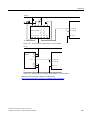
3.4 Installing the Control Unit
3.4
Installing the Control Unit
Locating the Control Unit on the power unit
The Control Unit is simply snapped-on to a Power Module. This also establishes all of the
electrical connections between the two components.
The Control Unit can be removed by pressing the release button ③.
Removing the terminal cover
To access the control terminals, remove the
cover as shown in the adjacent diagram.
• Maximum cable cross-section for control
terminals, 2.5 mm2.
• Tightening torque, 0.25 Nm
CU240S and CU240E Control Units, FW 3.2
Operating Instructions, 03/2009, A5E02440075B AA
41
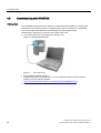
Connection
3.4 Installing the Control Unit
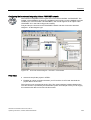
3.4.1
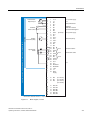
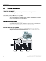
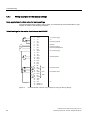
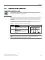
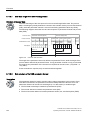
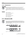
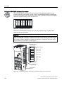
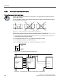
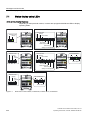
Interfaces, connectors, switches, control terminals, LEDs on the CU
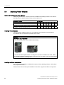
Overview of the process and user interfaces
The following interfaces are provided on the Control Unit
● Terminals for the input and output signals
● Card slot to upload and download inverter settings
● Connector to communicate with higher-level controls
● DIP switches to configure the speed encoder, the analog inputs and, if required, to set the
PROFIBUS address.
● LEDs for diagnostics
All of the these interfaces are shown in the following diagram.
00&FDUGVORW
',3VZLWFKHVIRUVHWWLQJWKH352),%86DGGUHVV
RQWKHVLGHRIWKH&8RQO\IRU'3YHUVLRQV
',3VZLWFKHVIRUFRQILJXULQJWKH
DQDORJLQSXWVDQGHQFRGHU
,QWHUIDFHIRU%233&FRQQHFWLRQNLW
/('IRUWKHLQYHUWHUVWDWXVGLVSOD\
7HUPLQDOVIRUGLJLWDORUDQDORJLQSXWDQG
RXWSXWVLJQDOV
',3VZLWFKIRUEXVWHUPLQDWLQJUHVLVWRU
&RPPXQLFDWLRQLQWHUIDFHWRDKLJKHUOHYHOFRQWURODV
68%'RU5-FRQQHFWRU
&86
Figure 3-3
42
6KLHOGSODWH
&8(
User interfaces of the CU240E/S
CU240S and CU240E Control Units, FW 3.2
Operating Instructions, 03/2009, A5E02440075B AA
Connection
3.4 Installing the Control Unit
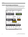
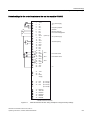
3RWHQWLRPHWHU
6HWSRLQWLQSXW
'LVSOD\
$FWXDOIUHTXHQF\
&86&86'3&86'3)&8631&8631)
&8(
6ZLWFKHV
0RWRUFRQWURO
6LJQDOOLJKWV
)DXOWV
9SRZHUVXSSO\
9
)UHTXHQ]VROOZHUW
212))
'LUHFWLRQUHYHUVDO
)DXOWDFNQRZOHGJPHQW
9SRZHUVXSSO\
$FWXDOIUHTXHQF\
'ULYHIDXOWDFWLYH
'ULYHDODUPDFWLYH
9
)',$
)',%
)',$
)',%
',
',
',
(1&$3
$1&$1
(1&%3
(1&%1
(1&=3
(1&=1
7HUPLQDOVIRUIDLOVDIHYHUVLRQVRQO\IRU&8(
Figure 3-4
9
9
$,
$,
',
',
',
',
89
)',$
$,
$,
$2
$2
37&
37&
',
',
1&
12
'2
&20
12
'2
&20
1&&
'2
12
&20
$2
$2
89
56$
56%
9
9
(1&
6XSSO\
Block diagram, CU 240
CU240S and CU240E Control Units, FW 3.2
Operating Instructions, 03/2009, A5E02440075B AA
43
Connection
3.4 Installing the Control Unit
Arrangement and function of the terminals on the CU240S Control Unit
All Control Units are equipped with the same control terminals. However, depending on the
CU version, the factory set activation for certain digital inputs and interfaces differ. (see the
block diagram for CU240S/E and for CU240S-DP/CU240S-DPF/CU240S-PN/CU240S-PNF).
Unlike the standard Control Units, the fail-safe Control Units CU240S DP-F and CU240S
PN-F only have six digital inputs instead of nine. They are instead equipped with two fail-safe
digital inputs. Fail-safe digital inputs are redundant and each have two terminals.
'LJLWDO
RXWSXW
'LJLWDO
RXWSXW
'LJLWDO
RXWSXW
'2 '2 '2 '2 '2
1& 12 &20 1& &20
'2 '2
12 &20
'LJLWDOLQSXWV
(QFRGHU
FRQQHFWRU
(1& (1& (1& (1& (1& (1&
$3 $1 %3 %1 =3 =1
',
',
',
',
',
',
',
',
IRUIDLOVDIH&8V
&86'3)
&8631)
7ZRIDLOVDIHGLJLWDOLQSXWV
$QDORJ
LQSXW
$QDORJ
RXWSXW
44
(1& 89 89
6833/< 287 287
$QDORJ
LQSXW
$QDORJ
RXWSXW
9 9 9 9 37& 37&
,1
,1 287 287 9RXWSXW
([WHUQDO9
VXSSO\
Figure 3-5
)', )', )', )',
$ % $ %
$, $, $2 $2
'LJLWDOLQSXWV
(QFRGHUSRZHU9
VXSSO\
RXWSXW
IRUVWDQGDUG&8V
&86&86'3
&8631
',
$, $, $2 $2
7HPSHUDWXUHVHQVRU
Terminal overview: CU240S-DP /-DP-F/ -PN /-PN-F
CU240S and CU240E Control Units, FW 3.2
Operating Instructions, 03/2009, A5E02440075B AA
4
Commissioning
Alternative commissioning options
The functions of an inverter are activated and configured using parameters. Parameters can
either be accessed from the operator control/display instrument (operator panel) or using the
STARTER commissioning tool from the PC via the appropriate inverter interface.
Inverters can also be parameterized by saving the valid inverter parameter set on an MMC
memory card or on the Operator Panel and then transferring it to a different inverter with the
same configuration and function.
The commissioning scenarios listed below are described in the following sections:
● Commissioning, using the factory settings
● Commissioning using the STARTER commissioning tool
● Commissioning using the Operator Panel
● Data backup with the Operator Panel and MMC memory card
Users can access the inverter parameters via the following interfaces
67$57(5YLD
)LHOGEXV
67$57(5YLD
3&FRQQHFWLRQ
NLW
%23
RQ&8
00&
&8
2SWLRQSRUW
866DW56
866352),%86352),1(7
CU240S and CU240E Control Units, FW 3.2
Operating Instructions, 03/2009, A5E02440075B AA
45
Commissioning
4.1 Initial coupling of the CU and PM - message F0395
4.1
Initial coupling of the CU and PM - message F0395
Description
Message "F0395" is displayed when Control Units or Power Modules are switched on for the
first time or after they have been replaced.
Using this message F0395, the two inverter components - Control Unit and Power Module are monitored to ensure that they are not replaced without the appropriate authorization. If
you acknowledge this message, then you accept the responsibility that the parameter set on
the Control Unit matches the Power Module and the hardware has been correctly connected,
e.g. all of the output phases have been correctly connected.
Acknowledging message F0395
Depending on which command source is set, you can acknowledge message F0395 in the
following ways:
● If the command source is "BOP": press function key FN
● If the command source is 'Terminals' (P0700 = 2): digital input 2 (factory setting for the
acknowledge command)
● If the command source is 'Fieldbus' (P0700 = 6): control word 1 (STW1 / bit 7)
Message F0395 is also acknowledged when 'Restoring the factory setting'.
46
CU240S and CU240E Control Units, FW 3.2
Operating Instructions, 03/2009, A5E02440075B AA
Commissioning
4.2 Restoring the factory settings
4.2
Restoring the factory settings
If nothing else works, restore the factory settings!
You can restore the factory setting using parameter P0970.
Table 4- 1
Restoring the factory settings
Parameter or
procedure
Description
P0003 = 1
User access level
1: Standard
P0010 = 30
Commissioning parameter
30: Factory setting - initiate restore factory settings
P0970 = 1
Restore factory settings
1: Resetting - restoring parameters to the factory settings
BOP displays "BUSY"
Once the factory settings have been restored, P0970 and P0010 are set to 0
and the BOP returns to the standard display.
STARTER displays
progress bar
Note
Data transfer is interrupted while the factory parameter settings are being restored.
The following parameters remain unchanged even after the factory settings have been
restored:
• P0014 Storage mode
• P0100 Europe / North America
• Communication parameters
• Power-Module-specific data
CU240S and CU240E Control Units, FW 3.2
Operating Instructions, 03/2009, A5E02440075B AA
47
Commissioning
4.3 Preparing commissioning
4.3
Preparing commissioning
Prerequisites: before you start
Before you start parameterization, you should clarify the following issues about
commissioning your application.
Are the factory settings sufficient for your application?
To start, check which factory settings you can use and which settings you wish to change
(see Section 'Commissioning with factory settings' (Page 51)). When doing so, you may find
that you only need to change just a few parameters.
Which motor are you using? [P0300]
● A synchronous or induction motor?
The SINAMICS inverters are preset in the factory for applications using 4-pole three-phase
induction motors that correspond to the performance data of the inverter.
Motor data / data on the motor rating plate
If you use the STARTER commissioning tool and a SIEMENS motor, you only have to
specify the motor Order No. In all other cases, you must read-off the data from the motor
rating plate and enter into the appropriate parameters.
P0305
P0310
P0304
3~Mot
1LA7130-4AA10
No UD 0013509-0090-0031
P0307
P0308
48
TICI F
EN 60034
1325 IP 55
IM B3
50 Hz
230/400 V ∆/Υ
60 Hz
460 V
5.5kW
19.7/11.A
6.5kW
10.9 A
Cos ϕ 0.81
1455/min
Cos ϕ 0.82
1755/min
∆/Υ 220-240/380-420 V
Υ 440-480
19.7-20.6/11.4-11.9 A
11.1-11.3 A
P0311
95.75%
45kg
P0309
CU240S and CU240E Control Units, FW 3.2
Operating Instructions, 03/2009, A5E02440075B AA
Commissioning
4.3 Preparing commissioning
NOTICE
Information about installation
The rating plate data that you enter must correspond to the connection type of the motor
(star connection [Y]/ delta connection [Δ]), i.e. for a delta motor connection, the delta rating
plate data must be entered.
In which region of the world is the motor used? - Motor standard [P0100]
● Europe ICE: 50 Hz [kW] - factory setting
● North America NEMA: 60 Hz [hp] or 60 Hz [kW]
Are you using an external speed encoder, and if yes, what is its resolution? [P0400]
● Speed encoder type
● Number of encoder pulses (resolution) per revolution
What is the prevailing temperature where the motor is operated? [P0625]
● Motor ambient temperature [P0625], if it differs from the factory setting = 20° C.
What control mode do you want to use for your application? [P1300]
A distinction is made between V/f open-loop control and vector closed-loop control.
● The V/f open-loop control is the simplest operating mode for an inverter. For example, it
is used for applications involving pumps, fans or motors with belt drives.
● For closed-loop vector control, the speed deviations between the setpoint and actual
value are less than for V/f open-loop control; further, it is possible to specify a torque. It is
suitable for applications such as winders, hoisting equipment or special conveyor drives.
CU240S and CU240E Control Units, FW 3.2
Operating Instructions, 03/2009, A5E02440075B AA
49
Commissioning
4.3 Preparing commissioning
What command and setpoint sources are you using?
The command and setpoint sources that are available depend on the inverter. Depending on
whether you use an inverter with or without fieldbus interface, with or without fail-safe
functions, the default command and setpoint sources set in the factory differ.
● Possible command sources [P0700]
– Operator Panel
– Fieldbus (factory setting for bus-capable and fail-safe inverters)
– Local digital inputs/switches (factory setting for non-bus-capable inverters)
● Possible setpoint sources [P1000]
– Motorized potentiometer
– Analog setpoint
– Fixed frequency
– Fieldbus
Controlling motors via terminals
There are various methods to start, stop and reverse the direction of a motor. The various
methods can be configured using parameter P0727.
The following two-wire control versions are available with the factory setting (P0727 = 0):
● Switching on and off with one control command and reversing with the second control
command.
● Switching on and switching off a direction of rotation with each control command.
Minimum/maximum frequency of the motor
The minimum and maximum frequency with which the motor operates or is limited
regardless of the frequency setpoint.
● Minimum frequency [P1080] - factory setting 0 Hz
● Maximum frequency [P1082] - factory setting 50 Hz
Ramp-up time and ramp-down time
The ramp-up and ramp-down time define the maximum motor acceleration when the speed
setpoint changes. The ramp-up and ramp-down time is the interval between motor standstill
and the maximum frequency, or between the maximum frequency and motor standstill.
● Ramp-up time [P1120] - factory setting 10 s
● Ramp-down time [P1121] - factory setting 10 s
50
CU240S and CU240E Control Units, FW 3.2
Operating Instructions, 03/2009, A5E02440075B AA
Commissioning
4.4 Commissioning with factory settings
4.4
Commissioning with factory settings
Prerequisites for using the factory settings
In simple applications, commissioning can be carried out just using the factory settings. This
section explains what prerequisites must be fulfilled for this purpose and how they are
fulfilled.
1. The inverter and motor must match one another; compare the data on the motor rating
plate with the technical data of the Power Module.
– The rated inverter current must, as a minimum, be the same as the motor.
– The motor power should match that of the inverter; motors can be operated in the
power range from 25 % … 100 % of the inverter power rating.
2. The digital and analog inputs must be connected in accordance with the wiring example.
(See Section 'Wiring example (Page 52) ')
3. You then have to "tell" the inverter the following,
– the source of its commands:
- from an operator panel,
- from the digital inputs
- from the fieldbus interface
You can change this command source using parameter P0700 if the factory setting is
not appropriate for your application.
– where it gets its speed setpoint (setpoint source)
- from an analog input (analog setpoint)
- as fixed frequency from a digital input
- from the fieldbus interface
You can change this frequency setpoint source using parameter P1000 if the factory
setting is not appropriate for your application.
CU240S and CU240E Control Units, FW 3.2
Operating Instructions, 03/2009, A5E02440075B AA
51
Commissioning
4.4 Commissioning with factory settings
4.4.1
Wiring examples for the factory settings
Many applications function using the factory settings
To ensure that the factory setting can be used, you must wire the control terminals on your
inverter as shown in the following examples.
Default settings for the control terminals on the CU240E
Figure 4-1
52
9
9
$,
$,
',
',
',
',
89
$,
$,
$2
$2
37&
37&
',
',
1&
12
'2
&20
12
'2
&20
1&&
'2
12
&20
$2
$2
89
56$
56%
9SRZHUVXSSO\
9
)UHTXHQF\VHWSRLQW
212))
'LUHFWLRQUHYHUVDO
)DXOWDFNQRZOHGJHPHQW
9SRZHUVXSSO\
$FWXDOIUHTXHQF\
'ULYHIDXOWDFWLYH
'ULYHDODUPDFWLYH
9
CU240E terminal overview: wiring example for using the factory settings
CU240S and CU240E Control Units, FW 3.2
Operating Instructions, 03/2009, A5E02440075B AA
Commissioning
4.4 Commissioning with factory settings
Default settings for the control terminals on the non-bus-capable CU240E
9
9
$,
$,
',
',
',
',
89
$,
$,
$2
$2
37&
37&
',
',
1&
12
&20
12
&20
1&&
12
&20
$2
$2
89
9
9
(1&
6XSSO\
',
',
',
(1&$3
$1&$1
(1&%3
(1&%1
(1&=3
(1&=1
9SRZHUVXSSO\
9
)UHTXHQF\VHWSRLQW
212))
'LUHFWLRQUHYHUVDO
(UURUDFNQRZOHGJHPHQW
)',$
9SRZHUVXSSO\
$FWXDOIUHTXHQF\
'2
'ULYHIDXOWDFWLYH
'2
'ULYHDODUPDFWLYH
'2
9
)',$
)',%
)',$
)',%
)DLOVDIHYHUVLRQVLQEUDFNHWV
Figure 4-2
CU240S terminal overview: wiring example for using the factory settings
CU240S and CU240E Control Units, FW 3.2
Operating Instructions, 03/2009, A5E02440075B AA
53
Commissioning
4.4 Commissioning with factory settings
4.4.2
Factory setting of the frequency inverter
Default command and setpoint sources
Inverters used in automation solutions have the appropriate fieldbus interfaces. These
inverters are preset in the factory so that the appropriate control and status signals can be
exchanged via the fieldbus interface.
Inverters without a fieldbus interface are pre-set in the factory so that the digital and analog
and input output signals are exchanged via terminals.
For instance, if you do not want to control an inverter equipped with a fieldbus interface via
the fieldbus, but instead using switches and pushbuttons that are connected to the digital
inputs, then you must change parameter P0700 as follows.
Table 4- 2
Command and setpoint sources
Parameters
Description
P0700 = 2 or 6
Select the command source
2: Digital intputs (P0701 … P0709) (factory setting for CUs without fieldbus interface)
6: Fieldbus (P2050 … P2091), (factory setting for CUs with fieldbus interface)
P1000 = 2 or 6
Select the setpoint source
2: Analog setpoint (factory setting for CUs without fieldbus interface)
6: Fieldbus (factory setting for CUs with fieldbus interface)
Table 4- 3
Factory settings of additional important parameters
Parameter
Factory setting Meaning of the factory setting
Function
Access
level
P0003
1
Access to the most frequently used Selecting the user access level
parameters
1
P0004
0
All parameters are displayed
Parameter filter: filters parameters in
accordance with the functionality
1
P0010
0
Ready to be entered
Commissioning parameter
1
P0100
0
Europe [50 Hz]
Frequency of the regional supply network
• IEC, Europe
• NEMA, North America
1
P0300
1
Induction motor
Select the motor type (induction motors /
synchronous motor)
2
P0304
400
[V]
Rated motor voltage
(in accordance with the rating plate in V)
1
P0305
depends on
the
Power Module
[A]
Rated motor current
(in accordance with the rating plate in A)
1
P0307
depends on
the
Power Module
[kW/hp]
Rated motor output
(in accordance with the rating plate in
kW/hp)
1
P0308
0
[cos phi]
Rated motor power factor (in accordance
with the rating plate in cos 'phi') if P0100 =
1.2, then P0308 is irrelevant
1
54
CU240S and CU240E Control Units, FW 3.2
Operating Instructions, 03/2009, A5E02440075B AA
Commissioning
4.4 Commissioning with factory settings
Parameter
Factory setting Meaning of the factory setting
Function
Access
level
P0309
0
[%]
Rated motor efficiency (in accordance with
the rating plate in %) if P0100 = 0, then
P0309 is irrelevant
1
P0310
50
[Hz]
Rated motor frequency
(in accordance with the rating plate in Hz)
1
P0311
1395
[rpm]
Rated motor speed
(in accordance with the rating plate in rpm)
1
P0335
0
Non-ventilated: Shaft-mounted fan
in the motor
Motor cooling (specify the motor cooling
system)
2
P0625
20
[°C]
Ambient temperature of motor
3
P0640
200
[%]
Motor overload factor (entered in % referred
to P0305)
2
P0700
2 or 6
2 for non-bus-capable CUs
6 for bus-capable CUs
Select the command source
1
P0727
0
DI0: On / off
DI1: Direction reversal
Control response when the motor starts
(start, stop, reverse)
3
P0970
0
Locked
Restore factory settings
1
P1000
2 or 6
2 for non-bus-capable CUs
6 for bus-capable CUs
Select the source of the frequency setpoint
(setpoint input)
1
P1080
0
[Hz]
Minimum frequency
1
P1082
50
[Hz]
Maximum frequency
1
P1120
10
[s]
Ramp-up time
1
Ramp-down time
P1121
10
[s]
P1300
0
V/f control with linear characteristic Control mode
2
P3900
0
No quick commissioning
1
CU240S and CU240E Control Units, FW 3.2
Operating Instructions, 03/2009, A5E02440075B AA
Completes the quick commissioning
1
55
Commissioning
4.4 Commissioning with factory settings
4.4.3
Default terminal settings
Factory settings of the process interfaces
Digital inputs
Terminal
Abbreviation
Parameter
Factory setting
Meaning of the factory setting
5
DI0
P0701
1
ON/OFF1
6
DI1
P0702
12
Direction reversal
7
DI2
P0703
9
Fault acknowledgment
8
DI3
P0704
15
Fixed frequency selector bit 0 (direct) [P1001]
16
DI4
P0705
16
Fixed frequency selector bit 1 (direct) [P1002]
17
DI5
P0706
17
Fixed frequency selector bit 2 (direct) [P1003]
40
DI6
P0707
18
Fixed frequency selector bit 3 (direct) [P1004]
41
DI7
P0708
0
Digital input locked
42
DI8
P0709
0
Digital input locked
Digital inputs of the safety functions
Terminal
Abbreviation
Parameter
Factory setting
Meaning of the factory setting
60
FDI0A
P9603
0
Digital inputs of the safety functions are locked
61
FDI0B
62
FDI1A
63
FDI1B
Terminal
Abbreviation
Parameters Factory setting
Meaning of the factory setting
18
NC
DO0
P0731
52.3
Drive fault active
19
NO
20
COM
21
NO
DO1
P0732
52.7
Drive alarm active
22
COM
23
NC
DO2
P0733
0.0
Relay output is locked
24
NO
25
COM
Digital outputs (relay outputs)
56
CU240S and CU240E Control Units, FW 3.2
Operating Instructions, 03/2009, A5E02440075B AA
Commissioning
4.4 Commissioning with factory settings
Analog inputs
Terminal
Abbreviation
Parameters
Factory setting
Meaning of the factory setting
3
AI0+
AI0
P0756 [0]
0
4
AI0-
Set unipolar voltage input
0 V … +10 V DC
in addition to parameterizing DIP switch on CU housing.
10
AI1+
AI1
P0756 [1]
0
11
AI1-
Set unipolar voltage input
0 V … +10 V DC
in addition to parameterizing DIP switch on CU housing.
Analog outputs
Terminal
Abbreviation
12
AO0+
Parameters
Factory setting
Meaning of the factory setting
AO0
P0771[0]
21
Frequency on the inverter output;
analog output 0 can be switched from current output to
voltage output by means of P0776
13
AO0-
26
AO1+
AO1
P0771[1]
21
Frequency on the inverter output;
analog output 1 is current output only
27
AO1-
Encoder interface (encoder)
Terminal
Function
Parameter
Factory setting
Meaning of the factory setting
70
Channel A non-inverting
P0400
0
Evaluation of the speed encoder is locked
71
Channel A inverting
72
Channel B non-inverting
73
Channel B inverting
74
Zero pulse non-inverting
75
Zero pulse inverting
Terminal
Abbreviation
Parameters
Factory setting
Meaning of the factory setting
14
PTC+
P0601
0
Evaluation of the motor temperature sensor is locked
15
PTC-
PTC/KTY84 interface
CU240S and CU240E Control Units, FW 3.2
Operating Instructions, 03/2009, A5E02440075B AA
57
Commissioning
4.5 Commissioning with STARTER
4.5
Commissioning with STARTER
Prerequisites
The STARTER commissioning tool features a project Wizard that guides you step-by-step
through the commissioning process. Configuring the inverter using the PC is significantly
more user friendly and faster than commissioning using the operator panel.
The following is required to commission the inverter via the PC:
● A PC connection kit for connecting the inverter to a PC.
Order no.: 6SL3255-0AA00-2AA1
Figure 4-3
PC connection kit
● The installed STARTER software.
(supplied with the PC connection kit). You can download the latest version from the
Internet under the following address
(http://support.automation.siemens.com/WW/view/en/10804985/133100):
● The motor must be connected to the inverter.
58
CU240S and CU240E Control Units, FW 3.2
Operating Instructions, 03/2009, A5E02440075B AA
Commissioning
4.5 Commissioning with STARTER
4.5.1
Description
Creating a STARTER project
An inverter can be parameterized in a user-friendly fashion using the Project Wizard. The
commissioning procedure described here follows the Project Wizard. The PC communicates
with the inverter via the USS interface.
● Switch on the inverter supply voltage
● Launch the STARTER commissioning tool.
● Use the Project Wizard and click on the "Find drive units online ..."
Figure 4-4
Start field
● In the screen that follows (not shown here), enter a meaningful name into your project,
e.g. "Basic Commissioning" and click on "Continue". The following dialog box is
displayed.
Figure 4-5
Setting the PC interface
● Click "Change and test..." to set up the PG/PC interface.
CU240S and CU240E Control Units, FW 3.2
Operating Instructions, 03/2009, A5E02440075B AA
59
Commissioning
4.5 Commissioning with STARTER
PG/PC - Set interface
● Select "PC COM-Port (USS)" from the list and click on "Properties …"
Figure 4-6
Setting the USS interface
● If "PC COM-Port (USS)" is not available, click on "Select …" to install the "PC COM-Port
(USS)" interface as shown in the "Install/Remove Interfaces" dialog box.
Figure 4-7
60
Installing the USS interface
CU240S and CU240E Control Units, FW 3.2
Operating Instructions, 03/2009, A5E02440075B AA
Commissioning
4.5 Commissioning with STARTER
● If you have installed the "PC COM-Port (USS)" interface, close the dialog box and now
call up "Properties - PC COM-Port (USS)".
Figure 4-8
PC COM properties
● In this dialog box, you can set the COM interface (COM1, COM2, COM3) and baud rate
(default: 38400).
● To determine the correct values of your interface, choose e.g. COM1, and then click on
"Read".
● Under the "RS 485" tab, in addition, select the "Automatic mode". Using various baud
rates in succession, the PC checks whether communications have been established to
the inverter. This can take several minutes.
● If "???" is displayed in the Baud rate test field then the baud rate test was unsuccessful.
and you should choose a different COM interface. In the case of the correct COM
interface, a value is displayed. Enter this value into the "baud rate" selection field.
CU240S and CU240E Control Units, FW 3.2
Operating Instructions, 03/2009, A5E02440075B AA
61
Commissioning
4.5 Commissioning with STARTER
● When you click "OK", the "Set PG/PC Interface" dialog box is displayed again.
Tip
In the "Set PG/PC Interface" dialog box, you can view the stations that can be accessed
via USS by choosing "Diagnostics...":
● When you choose "OK" again, this takes you back to the Project Wizard.
● By clicking on "Continue", a search is made for devices that are available online and you
then come to the step "Insert drives".
62
CU240S and CU240E Control Units, FW 3.2
Operating Instructions, 03/2009, A5E02440075B AA
Commissioning
4.5 Commissioning with STARTER
Insert drives
Figure 4-9
Insert drives
● In this dialog box, enter a name for your inverter, e.g. "SINAMICS_G120_CU240S" (no
blanks or special characters).
● Click on "Next".
● Close the "Summary" dialog box by choosing "Finish".
CU240S and CU240E Control Units, FW 3.2
Operating Instructions, 03/2009, A5E02440075B AA
63
Commissioning
4.5 Commissioning with STARTER
4.5.2
Establishing an online connection between the PC and converter (going "online")
Description
With the procedure described above, the project has been created and your inverter is
integrated into the project tree. However, there is no online connection.
● Click on
("Connect to the target system"), in order to go online with the inverter.
The left-hand column in the dialog box below contains the online data that has been saved,
while the right-hand column contains the offline data that has been saved.
● Click on "Load HW configuration to PG" to download the online data into your PC.
Figure 4-10
Inverters found online (using the SINAMICS G120 with Control Unit CU240S DP as
example)
● To conclude your entry, choose "Close".
● The status display changes from the "Offline mode" with blue background into the "Online
mode" with yellow background.
64
CU240S and CU240E Control Units, FW 3.2
Operating Instructions, 03/2009, A5E02440075B AA
Commissioning
4.5 Commissioning with STARTER
4.5.3
Starting the general commissioning
Description
● When the final dialog box in the "Going online" section is closed, the text "Offline mode"
in the bottom right of the dialog box changes to "Online mode".
Figure 4-11
Going online with STARTER (example with SINAMICS G120)
● For modular inverters that comprise a Control Unit and Power Module, when first
powered-up and after replacing a control unit or a Power Module, message F0395 is
output. This message is intentional and does not indicate that the inverter is faulty. This
message monitors the individual inverter components (CU and PM) against unauthorized
replacement.
● Select and acknowledge message F0395 that is present as described in the Section
"Initial coupling of the CU and PM".
Note
For information about the symbols used in STARTER, call up the online help. Press
<Shift><F1> and choose the relevant symbol. For example:
● Open the drive unit (
), by double clicking on the drive object ( )
● Click on "Wizard ..." for the (basic) commissioning, and let the Wizard guide you.
CU240S and CU240E Control Units, FW 3.2
Operating Instructions, 03/2009, A5E02440075B AA
65
Commissioning
4.5 Commissioning with STARTER
Carrying out commissioning
The Project Wizard navigates you step-by-step using pull-down menus through the basic
settings for your application.
● You get to the next menu item by pressing, choose "Next".
Figure 4-12
66
Start field: commissioning
CU240S and CU240E Control Units, FW 3.2
Operating Instructions, 03/2009, A5E02440075B AA
Commissioning
4.5 Commissioning with STARTER
● For the "Drive functions" menu item, we recommend that motor data identification:
"Locked" should be selected.
Figure 4-13
Deselecting motor data identification
Note
Motor data identification
Motor data identification is only required for vector control - and it is described there.
CU240S and CU240E Control Units, FW 3.2
Operating Instructions, 03/2009, A5E02440075B AA
67
Commissioning
4.5 Commissioning with STARTER
● For the menu item "Calculation of the motor data", we recommend that you select
"Restore factory settings and calculate motor data".
Figure 4-14
68
Calculating the motor data and restoring the factory setting
CU240S and CU240E Control Units, FW 3.2
Operating Instructions, 03/2009, A5E02440075B AA
Commissioning
4.5 Commissioning with STARTER
● The Project Wizard for the (first) commissioning is concluded with the following summary:
Figure 4-15
Completing commissioning
● Finally, choose "Finish".
CU240S and CU240E Control Units, FW 3.2
Operating Instructions, 03/2009, A5E02440075B AA
69
Commissioning
4.5 Commissioning with STARTER
4.5.4
Commissioning the application
Description
● You can now commission your application using the "Drive Navigator" screens or by
using the functions available in the project tree.
● Save your settings so that they are protected against power failure (see below).
● Once you have commissioned your application, disconnect the online connection
between the PC and inverter by clicking on
.
Figure 4-16
Application communication
Storing data in a power-independent manner
● In the project tree, select your SINAMICS project
● Double-click on "Drive Navigator".
● Select "Commissioning" in the working area
● In the dialog box, select "Save data in the drive (RAM to ROM)".
You can now disconnect the online connection with
70
"Disconnect from target system"
CU240S and CU240E Control Units, FW 3.2
Operating Instructions, 03/2009, A5E02440075B AA
Commissioning
4.6 Commissioning with the operator panel
4.6
Commissioning with the operator panel
4.6.1
Function of the Basic Operator Panel
The Basic Operator Panel (BOP) offers various commissioning options and ways tosave
data and transfer data with the BOP (Page 77).
The Basic Operator Panel can be used to commission drives, monitor operation and set
individual parameters. The keys can be used, for example, to set control signals and the
speed setpoint. Parameter changes that are made using the BOP are saved so that they are
protected against power failure.
The Basic Operator Panel for 'local' operation and how to attach it to the Control Unit
How to attach the BOP to the Control Unit.
The Basic Operator Panel is an input and display instrument that allows you to operate
inverters "locally". A BOP can be used for more than one inverter and is mounted directly on
a Control Unit.
The BOP has 8 keys and a 2-line screen for displaying values and units:
● Line 1 shows a parameter number or value
● Line 2 shows the corresponding physical unit
CU240S and CU240E Control Units, FW 3.2
Operating Instructions, 03/2009, A5E02440075B AA
71
Commissioning
4.6 Commissioning with the operator panel
4.6.2
BOP controls and displays
How to use the BOP
Table 4- 4
Key
Operator controls of the Basic Operator Panel and its functions
Function
Function / result
Status LED
Shows parameter numbers, values, and physical units of
measure.
Parameter access
This button allows you to access the parameter list.
r _ _ _ _ read-only parameters: for display only
P_ _ _ _ write parameters: these can be changed
Increase displayed
values
This button allows you to scroll forwards in the parameter
list;
Decrease displayed
values
This button allows you to scroll backwards in the parmeter
list.
Function key
The function of this button varies depending on the data
displayed:
If a parameter number is displayed and you press this
button once briefly, you can return to the start of the
parameter list r0000.
If a parameter value is displayed and you press this
button once briefly, the cursor jumps to the next position
(e.g. in a multi-digit number). This allows you to change a
decimal number digit by digit, for example.
If an alarm or a fault message is displayed and you press
this button once briefly, this acknowledges the message.
Start motor
Press this button to start the motor.
In the factory setting, this button is not active:
activate with P0700 = 1
Stop motor
Press this button to stop the motor.
OFF2 is always activated: Press twice briefly or press
once for longer: The motor coasts to a standstill.
In the factory setting, OFF1 is not active.
To activate it, set P0700 = 1.
Change direction of
rotation
When you press this button, the direction of motor rotation
is reversed (CW/CCW).
In the factory setting, this button is not active.
To activate it, set P0700 = 1.
Jog mode
Run the motor in jog mode. The motor rotates at a
predefined speed for as long as this key is pressed (and
kept down).
In the factory setting, this button is not active.
To activate it, set P0700 = 1.
72
CU240S and CU240E Control Units, FW 3.2
Operating Instructions, 03/2009, A5E02440075B AA
Commissioning
4.6 Commissioning with the operator panel
4.6.3
Parameterization with the BOP (two examples)
All of the parameter changes, which are made using the BOP, are saved so that they are
protected against power failure.
Changing a parameter value using the BOP
The following description is an example of how to change any parameter using the BOP.
Table 4- 5
Change P0003 (set user access level "3")
Step
Result displayed
1
Press
to access the parameters.
2
Press
until P0003 is displayed.
3
Press
to display the parameter value.
4
Press
or
5
Press
to confirm and save the value.
6
The user can now view all parameters in steps 1 to 3.
to set the required value (to 3).
Using the BOP to change parameters with more than one index
The next example shows how the value of an indexed parameter can be changed.
Table 4- 6
Change index parameter P0700 (set command source "BOP" under index 1)
Step
Result displayed
1
Press
to access the parameters.
2
Press
as often or as long as required until P0700 is displayed.
3
Press
: index "in000" is displayed.
4
Press
or
5
Press
to display the value that is currently set.
6
Press
or
7
Press
to confirm and save the value.
8
Press
until r0000 is displayed.
9
to reset the display to the standard drive display (as
Press
defined by the customer).
to select index 1.
until the required value is displayed.
Note
When parameter values are being changed, the BOP sometimes displays the message
"bUSY". This means that the inverter is currently processing a higher-priority task.
CU240S and CU240E Control Units, FW 3.2
Operating Instructions, 03/2009, A5E02440075B AA
73
Commissioning
4.6 Commissioning with the operator panel
4.6.4
Commissioning steps
The following section provides a step-by-step guide to quick commissioning, which is
sufficient for the majority of applications.
The first step in commissioning a drive train is to ensure that the inverter and motor are
harmonized. This inverter-motor combination can then be adapted in line with the
requirements of the drive machine
The inverter is adapted to the requirements of an application by parameterizing it. A
corresponding parameter list with explanations is provided on the following pages.
4.6.5
Commissioning V/f control
Since the load characteristic can be set as required, V/f control is sufficient for many drive
trains. A drive train that operates with V/f control with a linear characteristic can be set by
entering the following parameters.
Parameter settings for V/f control
Table 4- 7
Setting the access level and parameter filter
Parameters
Description
P0003 = 1
User access level
1: Standard: Allows access to the most frequently used parameters (factory setting)
2: Extended: Allows extended access, e.g. to inverter I/O functions
3: Expert: To be used by experts
P0010 = 1
Commissioning parameter filter
0: Ready (factory setting)
1: Quick commissioning
30: Factory setting - initiate restore factory settings
To parameterize the motor rating plate data, set P0010 = 1.
Table 4- 8
74
Data on the environmental conditions at the installation location
Parameters
Description
P0100 = 0
Europe / North America (line frequency of region)
0: Europe [kW], standard frequency 50 Hz (factory setting)
1: North America [hp], standard frequency: 60 Hz
2: North America [kW], standard frequency: 60 Hz
P0230 = 0
Output filter
0: No filter (factory setting)
P0233 = ...
Filter inductance of the output filter used
0.000 (factory setting)
P0234 = ...
Filter capacitance of the output filter used
0.000 (factory setting)
CU240S and CU240E Control Units, FW 3.2
Operating Instructions, 03/2009, A5E02440075B AA
Commissioning
4.6 Commissioning with the operator panel
Table 4- 9
Motor data in accordance with the specifications on the motor rating plate
Parameters
Description
P0304 = …
Rated motor voltage (enter value as specified on the motor rating plate in Volt)
400 [v] (factory setting)
The rating plate data entered must correspond to the motor connection type
(star/delta) (i.e. with a delta motor connection, the delta rating plate data must be
entered).
P0305 = …
Rated motor current (enter value as specified on the motor rating plate in Ampere)
1 [A] (factory setting)
P0307 = …
Rated motor power (enter value as specified on the motor rating plate in kW or hp)
0.37 [kW / hp] (factory setting)
If P0100 = 0 or 2, the data is specified in kW
If P0100 = 1, the data is specified in hp.
P0308 = ...
Rated motor power factor [cos phi]
0.820 (factory setting)
This parameter is irrelevant when P0100 = 1 or 2.
P0310 = …
Rated motor frequency (enter value as specified on the motor rating plate in Hz)
50.00 [Hz] (factory setting)
When this parameter is changed, the number of pole pairs for the motor is
automatically recalculated.
P0311 = …
Table 4- 10
Rated motor speed (enter value as specified on the motor rating plate in rpm)
1395 [U / min]
Specify command source and frequency setpoint source
Parameter
Description
P0700 = 2 or
6
Select the command source
0: Standard factory setting (restores the CU to the factory setting)
1: BOP (Basic Operator Panel keys)
2: Digital inputs (factory setting for 'stand-alone' CUs)
4: USS on RS 232
5: USS on RS 485
6: Fieldbus (factory setting for fieldbus-capable CUs)
P1000 = 2 or Select the setpoint source
6
0: No main setpoint
1: MOP setpoint
2: Analog setpoint (factory setting for stand-alone CUs)
3: Fixed frequency
4: USS at RS 232
5: USS at RS 485
6: Fieldbus (factory setting for fieldbus-capable CUs)
7: Analog setpoint 2
CU240S and CU240E Control Units, FW 3.2
Operating Instructions, 03/2009, A5E02440075B AA
75
Commissioning
4.6 Commissioning with the operator panel
Table 4- 11
Parameters that must be set in every application
Parameter
Description
P1080 = …
Minimum frequency
0.00 [Hz] factory setting
Enter the minimum frequency (in Hz) at which the motor runs independently of the
frequency setpoint. The value set here applies to CW and CCW rotation.
P1082 = …
Maximum frequency
50.00 [Hz] factory setting
Enter the maximum frequency (in Hz) to which the motor is restricted independently of
the frequency setpoint. The value set here applies to CW and CCW rotation.
P1120 = …
Rampup time
10.00 [s]
Enter the time (in seconds) in which the motor is to accelerate from standstill to the
maximum frequency (P1082).
If the ramp-up time is too short, alarm A0501 (current limit value) may be output or the
inverter is shut down with fault F0001 (overcurrent).
P1121 = …
Rampdown time
10.00 [s]
Enter the time (in seconds) during which the motor is to be decelerated (braked) from
the maximum frequency (P1082) to standstill. If the ramp-down time is too short,
alarm A0501 (current limit value) or A0502 (overvoltage limit value) may be output or
the inverter is shut down with fault F0001 (overcurrent) or F0002 (overvoltage).
Table 4- 12
End quick commissioning (= start internal motor data calculation)
Parameter
Description
P3900 = 1
End quick commissioning
0: No quick commissioning (factory setting)
1: Quick commissioning incl. restoring factory settings
- Calculate the motor data with the quick commissioning parameters
- Restore the factory settings for the I/O
- Restore the factory settings for all other parameters
2: Quick commissioning incl. restoring the factory settings for the I/O.
- Calculate the motor data with the modified quick commissioning parameters
- Restore the factory settings for the I/O
- All the other parameters remain unchanged
3: Quick commissioning with motor data only
- Calculate the motor data with the quick commissioning parameters
- I/O settings remain unchanged
- All the other parameters remain unchanged
When P3900 = 1, 2, or 3, the value for P1082 is written to P2000.
When quick commissioning is being completed, the message "bUSY" is displayed on
the BOP. This means that the system is in the process of calculating the control data
and saving the parameter values in the EEPROM.
Once quick commissioning has been carried out, P3900 and P0010 are set to 0.
When you press "FN" and "P" on the BOP, the actual frequency is displayed.
76
CU240S and CU240E Control Units, FW 3.2
Operating Instructions, 03/2009, A5E02440075B AA
Commissioning
4.7 Data backup with the operator panel and memory card
4.7
Data backup with the operator panel and memory card
4.7.1
Saving and transferring data using the BOP
The operator panel as a medium to backup and transfer data
You can save a parameter set on the operator panel and transfer it to other inverters, e.g. to
identically parameterize several devices or to transfer the settings after a device has been
replaced.
Prerequisites for transferring data sets from the operator panel to a different inverter
The Control Unit to which the parameter set is transferred must be of the same type and
have the same firmware release as the source Control Unit. (Same 'type' means: The same
Order No.)
Saving the parameters on the operator panel (upload)
Table 4- 13
Transfer data from the inverter to the operator panel
Parameters
Description
P0003 = 3
3: Expert
P0010 = 30
30: Initiating parameter transfer
P0802 = 1
1: Transfer data from theEEPROM (of the inverter) to the operator panel
•
•
If the upload procedure is successful, P0010 and P0802 are set to 0 and the "RDY"
LED lights up.
If the download procedure is unsuccessful, F0055 or F0057 is displayed and the
LED "SF" (red) lights up. In this case, make another attempt to transfer data.
Transferring parameters from the operator panel into the inverter (download)
Table 4- 14
Transfer data from the operator panel to the inverter
Parameters
Description
P0003 = 3
3: Access level 3
P0010 = 30
30: Initiating parameter transfer
P0803 = 1
1: Transfer data to theEEPROM (of the inverter) from the operator panel
•
•
If the upload procedure is successful, P0010 and P0803 are set to 0 and the "RDY"
LED lights up.
If the download procedure is unsuccessful, F0055 or F0057 is displayed and the
LED "SF" (red) lights up. In this case, make another attempt to transfer data.
CU240S and CU240E Control Units, FW 3.2
Operating Instructions, 03/2009, A5E02440075B AA
77
Commissioning
4.7 Data backup with the operator panel and memory card
4.7.2
Saving and transferring data using the MMC
The MMC memory card as a medium for backing up and transferring data
You can save a parameter set on the memory card and transfer it to other inverters, e.g. to
identically parameterize several devices or to transfer the settings after a device has been
replaced.
Data backup
The MMC is a removable, non-volatile flash memory for the parameter set of an inverter and
does not require a power supply. For instance, this can be used to transfer parameter
settings to a new inverter after the previous one was replaced.
We recommend that memory card MMC (Order No.: 6SL3254-0AM00-0AA0) should be
used.
Prerequisites for transferring data sets from the MMC to a different inverter
The Control Unit to which the parameter set is transferred must be of the same type and
have the same firmware release as the source Control Unit. (Same 'type' means: The same
Order No.)
Backup the parameters on the MMC memory card (upload)
Table 4- 15
Parameters
Transferring data from the inverter to the memory card
Description
Insert MMC
A0564
When saving data, this alarm can be ignored.
This alarm is only displayed if the value of parameter P8458 = 1 or 2 and means that
the MMC was inserted while the device was in operation and an MMC was not
inserted when the inverter was booted.
P0003 = 3
3: Expert
P0010 = 30
30: Initiating parameter transfer
P0802 = 2
2: Transfer data from theEEPROM (of the inverter) to the MMC. "RDY" LED flashes.
•
•
If the upload procedure is successful, P0010 and P0802 are set to 0 and the "RDY"
LED lights up.
If the download procedure is unsuccessful, F0061 or F0062 is displayed and the
LED "SF" (red) lights up. In this case, make another attempt to transfer data.
Remove the
MMC
Note
Time it takes to save the data
It can take several minutes to transfer data to the MMC memory card.
78
CU240S and CU240E Control Units, FW 3.2
Operating Instructions, 03/2009, A5E02440075B AA
Commissioning
4.7 Data backup with the operator panel and memory card
Transferring the parameters from the MMC memory card into the inverter (download)
Table 4- 16
Transferring data from the memory card to the inverter
Parameters
Description
P0003 = 3
3: Expert
P0010 = 30
30: Initiating parameter transfer
P0803 = 2
2: Transfer data to the EEPROM (of the inverter) from the MMC. "RDY" LED flashes.
•
•
If the upload procedure is successful, P0010 and P0803 are set to 0 and the "RDY"
LED lights up.
If the download procedure is unsuccessful, F0061 or F0062 is displayed and the
LED "SF" (red) lights up. In this case, make another attempt to transfer data.
CU240S and CU240E Control Units, FW 3.2
Operating Instructions, 03/2009, A5E02440075B AA
79
5
Functions
5.1
Overview of inverter functions
)DLOVDIHIXQFWLRQV
672
3URWHFWLRQIXQFWLRQV
672
66
&RPPDQGVRXUFHV
6%&
2YHUFXUUHQW
2YHUYROWDJH
'LJLWDOLQSXWV
2YHUWHPSHUDWXUH
2SHUDWRUSDQHO
)DLOVDIHFRP
PDQGVRXUFHV
352),VDIH
)DLOVDIHGLJLWDO
LQSXWV
6\VWHP
SURWHFWLRQ
)LHOGEXV
0RWRUFRQWURO
9IFRQWURO
9HFWRUFRQWURO
ZLWKRXWHQFRGHU
9HFWRUFRQWURO
ZLWKHQFRGHU
6HWSRLQWVRXUFHV
,QYHUWHUFRQWURO
7ZRZLUHFRQWURO
7KUHHZLUHFRQWURO
&RQWUROYLDILHOGEXV
$QDORJLQSXWV
)L[HGVHWSRLQWV
0RWRUL]HG
SRWHQWLRPHWHU
-2*VHWSRLQW
)LHOGEXV
7RUTXHFRQWURO
7HFKQRORJLFDO
IXQFWLRQV
6HWSRLQWFDOFXODWLRQ
)O\LQJUHVWDUW
6WDWXVPHVVDJHV
5DPSIXQFWLRQJHQHUDWRU
7HFKQRORJ\FRQWUROOHU
/LPLWDWLRQ
$XWRPDWLFUHVWDUW
6NLS
%UDNHFRQWURO
.LQHWLFEXIIHULQJ
'LJLWDORXWSXWV
$QDORJRXWSXWV
)LHOGEXV
'&EUDNH
3RVLWLRQLQJUDPS
8QDVVLJQHGIXQFWLRQEORFNV
Figure 5-1
Overview of inverter functions
CU240S and CU240E Control Units, FW 3.2
Operating Instructions, 03/2009, A5E02440075B AA
81
Functions
5.1 Overview of inverter functions
Functions relevant to all applications
The functions that you require in each application are located at the center of the function
overview above.
The parameters of these functions are provided with a matching basic setting during quick
commissioning so that in many cases, the motor can be operated without requiring additional
parameterization.
Inverter control is responsible for all of the other inverter functions. Among
other things, it defines how the inverter responds to external control signals.
The command source defines from where the control signals are received to
switch-on the motor, e.g. via digital inputs or a fieldbus.
The setpoint source defines how the speed setpoint is for the motor is
entered, e.g. via an analog input or a fieldbus.
The setpoint calculation uses a ramp-function generator to prevent speed
steps occurring and to limit the speed to a permissible maximum value.
0
82
The motor closed-loop control ensures that the motor follows the speed
setpoint.
CU240S and CU240E Control Units, FW 3.2
Operating Instructions, 03/2009, A5E02440075B AA
Functions
5.1 Overview of inverter functions
Functions required in special applications only
The functions, whose parameters you only have to adapt when actually required, are located
at the outer edge of the function overview above.
The production functions avoid overloads and operating states that could
cause damage to the motor, inverter and driven load. The motor temperature
monitoring is, e.g. set here.
The status messages provide digital and analog signals at the digital outputs
or via the fieldbus. Examples include the actual speed of the motor or fault
message output by the inverter.
The technological functions allow you to activate a motor holding brake or
implement a higher-level pressure or temperature control using the
technology controller, for example.
The safety functions are used for applications that must fulfill special
requirements placed on the functional safety. These are only available for
fail-safe inverters.
Connection to a fieldbus
866
352),%86
352),1(7
If you wish to operate the inverter on a fieldbus, then you must connect the following inverter
functions with the fieldbus:
● Command sources
● Setpoint sources
● Status messages
A connection with a fieldbus can be established via software tools in the control systems.
This manual includes descriptions of how you proceed for PROFIBUS and PROFINET with a
SIMATIC control.
CU240S and CU240E Control Units, FW 3.2
Operating Instructions, 03/2009, A5E02440075B AA
83
Functions
5.2 Inverter control
5.2
Inverter control
5.2.1
Frequency inverter control using digital inputs (two/three-wire control)
Configuring start, stop and direction of rotation reversal using digital inputs
If the inverter is controlled using digital inputs, using parameter P0727, you can define how
the motor responds when it is started, stopped, and the direction of rotation is changed
(reversing).
Five different methods are available for controlling the motor. Three of the five control
methods just require two control commands (two-wire control). The other two control
methods require three control commands (three-wire control).
The wide range of setting options is especially intended to be able to emulate existing control
methods on the plant or system side if the inverter has to be integrated into an existing
application. The two most common methods use the factory setting (P0727 = 0) and are
available as standard in SINAMICS inverters.
Note
When clockwise rotation is activated, the inverter generates a clockwise voltage
characteristic at its output terminals. Whether the connected motor actually rotates clockwise
depends on the wiring between the inverter and motor.
Factory setting for "start", "stop", and "direction reversal" control commands
In the factory setting (P0727 = 0), the motor is operated using two control commands. In this
case, two versions are available
Further methods for "start", "stop", and "direction reversal" control commands
Parameter P0727 offers three additional methods for controlling the motor.
● Method 3 for controlling the motor is ideal for drives where the direction of rotation is
manually changed, for instance, traction drives that are controlled from a master switch. It
functions similarly to method 2. Method 3 differs from method 2 with respect to how the
motor responds when both control commands are present at the same time, and that it
also allows you to change the direction of rotation at any time.
● Two further methods are available for controlling motors, each of which use three control
commands. With these methods, the motor is no longer controlled via the signal level
only but also with the positive signal edges of certain commands.
Just the same as method 3 of the two-wire control, the first three-wire control method is
especially suitable for drives where the direction of rotation is manually reversed.
84
CU240S and CU240E Control Units, FW 3.2
Operating Instructions, 03/2009, A5E02440075B AA
Functions
5.2 Inverter control
Table 5- 1
Comparison of the methods for two-wire motor control
Description
Control commands
0RWRU 0RWRUVWRSV 0RWRU 0RWRUVWRSV
URWDWLQJ
URWDWLQJ
&:
&&:
Two-wire control, method 1 (P0727=0)
1. Control command: Switch the motor on
or off
0RWRURQ
2. Control command: Reverses the motor
direction of rotation
5HYHUVHPRWRU
Two-wire control, method 2 (P0727=0)
If CW and CCW rotation are selected simultaneously, the signal that was issued first has priority. The
second signal is ignored.
The motor cannot be reversed as long as it is still rotating.
1. Control command: Switch on or switch
off the motor CW rotation
0RWRURQ
&:
W
2. Control command: Switch on or switch
off the motor CCW rotation
0RWRURQ
&&:
W
Two-wire control, method 3 (P0727=1)
When CW and CCW are simultaneously selected, the motor is stopped.
Reversing is possible at any time.
1. Control command: Switch on or switch
off the motor CW rotation
0RWRURQ
&:
W
2. Control command: Switch on or switch
off the motor CCW rotation
0RWRURQ
&&:
W
CU240S and CU240E Control Units, FW 3.2
Operating Instructions, 03/2009, A5E02440075B AA
85
Functions
5.2 Inverter control
Table 5- 2
Comparison of the methods for three-wire motor control
Explanation
Control commands
0RWRU 0RWRUVWRSV 0RWRU 0RWRUVWRSV
URWDWLQJ
URWDWLQJ
&:
&&:
Three-wire control, method 1 (P0727 = 2)
1. Control command: Enable the motor so
that it can be switched on or switched off
(QDEOHRU
VWRS
W
0RWRURQ
&:
W
0RWRURQ
&&:
2. Control command: Switch on the motor
CW rotation
3. Control command: Switch on motor
CCW rotation
W
Three-wire control, method 2 (P0727 = 3)
1. Control command: Enable the motor so
that it can be switched on or switched off
(QDEOH
W
0RWRURQ
W
5HYHUVH
PRWRU
2. Control command: Switch the motor on
or off
3. Control command: Enter CW or CCW
rotation of the motor
W
A detailed description of all of the methods to control a motor can be found in the following
sections.
86
CU240S and CU240E Control Units, FW 3.2
Operating Instructions, 03/2009, A5E02440075B AA
Functions
5.2 Inverter control
5.2.2
Two-wire control, method 1
Function description
This control method uses two control commands as permanent signals.
One control command starts/stops the motor, while the other control command changes the
direction of rotation.
0RWRU21
$FWLYH
5HYHUVH
PRWRU
$FWLYH
$FWLYH
0RWRU
VSHHG
R
W
R 2))
Figure 5-2
Two-wire control using digital inputs, method 1
Table 5- 3
Function table
Motor ON
Reverse
motor
0
0
Function
OFF1: The motor decelerates to a standstill
0
1
OFF1: The motor decelerates to a standstill
1
0
The motor accelerates to the setpoint
1
1
The motor accelerates to the inverted setpoint
Table 5- 4
Parameter
Parameterizing the function
Description
P0700 = 2
Controls the motor using the digital inputs of the inverter
P0727 = 0
Two-wire control, method 1 or 2
P0701 = 1
The motor is power-up with digital input 0
Further options:
The motor can be powered-up with any other digital input, e.g. with digital input 3 via
P0704 = 1
P0702 = 12
The motor is reversed with digital input 1
Further options:
The motor can be reversed with any other digital input, e.g. with digital input 3 via
P0704 = 12
CU240S and CU240E Control Units, FW 3.2
Operating Instructions, 03/2009, A5E02440075B AA
87
Functions
5.2 Inverter control
5.2.3
Two-wire control, method 2
Function description
This control method uses two control commands as permanent signals.
CW and CCW rotation of the motor is started and stopped with one control command each.
To change the direction, the drive must first decelerate to 0 Hz with OFF1 before the
direction reversal signal is accepted.
0RWRU21
&:
&RPPDQGLJQRUHG
$FW
$FWLYH
&RPPDQGLJQRUHG
0RWRU21
&&:
,QYHUWHU
RXWSXW
IUHTXHQF\
$FWLYH
R
R
R
W
R 2))
Figure 5-3
Two-wire control using digital inputs, method 2
Table 5- 5
Function table
Motor ON /
CW
Motor ON /
CCW
0
0
OFF1: The motor decelerates to a standstill
0
1
The motor accelerates to the inverted setpoint
1
0
The motor accelerates to the setpoint
1
1
The first active signal has priority; the second signal is ignored.
Table 5- 6
88
Function
Parameterizing the function
Parameter
Description
P0700 = 2
Controls the motor using the digital inputs of the inverter
P0727 = 0
Two-wire control, method 1 or 2
P0701 = 1
CW rotation is activated with digital input 0
Further options:
CW rotation can be activated with any other digital input, e.g. with digital input 3 via
P0704 = 1
P0702 = 2
CCW rotation is activated with digital input 1
Further options:
CCW rotation can be activated with any other digital input, e.g. with digital input 3 via
P0704 = 2
CU240S and CU240E Control Units, FW 3.2
Operating Instructions, 03/2009, A5E02440075B AA
Functions
5.2 Inverter control
5.2.4
Two-wire control, method 3
Function description
This control method uses two control commands as permanent signals.
Like method 2, CW and CCW rotation can be started/stopped by one control command
each. In contrast to method 2, however, the control commands can be switched at any time
regardless of the setpoint, output frequency, and direction of rotation. The motor does not
have to coast to 0 Hz either before a control command is executed.
0RWRU21
&:
$FW
$FWLYH
$FW
0RWRU21
&&:
$FW
$FWLYH
$FWLYH
0RWRU
VSHHG
R
R
R
R
R
W
R 2))
Figure 5-4
Two-wire control using digital inputs, method 3
Table 5- 7
Function table
Motor ON /
CW
Motor ON /
CCW
0
0
OFF1: The motor decelerates to a standstill
0
1
The motor accelerates to the inverted setpoint
1
0
The motor accelerates to the setpoint
1
1
OFF1: The motor decelerates to a standstill
Table 5- 8
Parameter
Function
Parameterizing the function
Description
P0700 = 2
Controls the motor using the digital inputs of the inverter
P0727 = 1
Two-wire control, method 3
P0701 = 1
CW rotation is activated with digital input 0
Further options:
CW rotation can be activated with any other digital input, e.g. with digital input 3 via
P0704 = 1
P0702 = 2
CCW rotation is activated with digital input 1
Further options:
CCW rotation can be activated with any other digital input, e.g. with digital input 3 via
P0704 = 2
CU240S and CU240E Control Units, FW 3.2
Operating Instructions, 03/2009, A5E02440075B AA
89
Functions
5.2 Inverter control
5.2.5
Three-wire control, method 1
Function description
● The first control command is a permanent enable signal for starting the motor. When this
enable signal is canceled, the motor stops.
● CW rotation is activated with the positive edge of the second control command.
● CCW rotation is activated with the positive edge of the third control command.
(QDEOH
VLJQDO
$FWLYH
$FWLYH
&RPPDQGLJQRUHG
0RWRU21
&:
0RWRU21
&&:
$FWLYH
0RWRU
VSHHG
R
R
W
R 2))
Figure 5-5
Table 5- 9
Function table
Enable
signal
Motor ON /
CW
0
Not
relevant
Not
relevant
1
0→1
0
1
0
0→1
1
0
0
No effect on the direction of rotation.
1
1
1
OFF1: The motor decelerates to a standstill
Table 5- 10
Parameter
90
Three-wire control using digital inputs, method 1
Motor ON / Function
CCW
OFF1: The motor decelerates to a standstill
The motor accelerates to the setpoint
The motor accelerates to the inverted setpoint
Parameterizing the function
Description
P0700 = 2
Controls the motor using the digital inputs of the inverter
P0727 = 2
Three-wire control, method 1
P0701 = 1
The enable signal to power-up the motor is issued with digital input 0
Further options:
The enable signal can be issued with any other digital input, e.g. with digital input 3
via P0704 = 1
P0702 = 2
CW rotation is activated with digital input 1
Further options:
CW rotation can be activated with any other digital input, e.g. with digital input 3 via
P0704 = 2
P0703 = 12
CCW rotation is activated with digital input 2
Further options:
CCW rotation can be activated with any other digital input, e.g. with digital input 3
via P0704 = 12
CU240S and CU240E Control Units, FW 3.2
Operating Instructions, 03/2009, A5E02440075B AA
Functions
5.2 Inverter control
5.2.6
Three-wire control, method 2
Function description
● The first control command is a permanent enable signal for starting the motor. When this
enable signal is canceled, the motor stops.
● The motor is started with the positive edge of the second control command.
● The third control command defines the direction of rotation.
(QDEOH
VLJQDO
$FWLYH
0RWRU21
$FWLYH
&RPPDQGLJQRUHG
$FWLYH
5HYHUVH
PRWRU
$FWLYH
$FWLYH
0RWRU
VSHHG
R
R
W
R 2))
Figure 5-6
Table 5- 11
Three-wire control using digital inputs, method 2
Function table
Enable
signal
Motor
ON
Reverse
motor
Function when motor is at a
standstill
Function when motor is
rotating
0
Not
relevant
Not relevant
No effect
OFF1: The motor decelerates
to a standstill
1
0→1
0
The motor accelerates to the
setpoint
No effect
1
0→1
1
The motor accelerates to the
inverted setpoint
No effect
1
0
1→0
No effect
The motor reverses to the
setpoint.
1
0
0→1
No effect
The motor reverses to the
inverted setpoint.
CU240S and CU240E Control Units, FW 3.2
Operating Instructions, 03/2009, A5E02440075B AA
91
Functions
5.2 Inverter control
Table 5- 12
Parameter
92
Parameterizing the function
Description
P0700 = 3
Controls the motor using the digital inputs of the inverter
P0727 = 3
Three-wire control, method 2
P0701 = 2
The enable signal to power-up the motor is issued with digital input 0
Further options:
The enable signal can be issued with any other digital input, e.g. with digital input 3
via P0704 = 2
P0702 = 1
The motor is started with digital input 1
Further options:
The motor can be started with any other digital input, e.g. with digital input 3 via
P0704 = 1
P0703 = 12
The direction of the motor is reversed with digital input 2
Further options:
The direction of the motor can be reversed with any other digital input, e.g. with
digital input 3 via P0704 = 12
CU240S and CU240E Control Units, FW 3.2
Operating Instructions, 03/2009, A5E02440075B AA
Functions
5.3 Command sources
5.3
Command sources
5.3.1
Selecting command sources
Selecting the command source [P0700]
The motor is switched on/off via external inverter control commands. The following command
sources can be used to specify these control commands:
● Operator control / display instrument (operator panel)
● Digital inputs
● Fieldbus
The command sources available depend on the inverter version.
● For inverters with a fieldbus interface, the 'fieldbus' (P0700 = 6) is pre-selected as the
command source,
● For inverters without a fieldbus interface, the digital inputs (P0700 = 2) are pre-selected
as command source.
Table 5- 13
Parameters, to select the source for the inverter control commands
Parameters
Description
P0700 = ...
0: Factory default setting
1: Operator panel
2: Digital inputs (P0701 … P0709), factory setting for an inverter without fieldbus
interface
4: USS at RS 232
5: USS at RS 485 (not available for all inverters)
6: Fieldbus (P2050 … P02091), factory setting for inverters with fieldbus interface.
CU240S and CU240E Control Units, FW 3.2
Operating Instructions, 03/2009, A5E02440075B AA
93
Functions
5.3 Command sources
5.3.2
Assigning functions to digital inputs
Assigning control commands to digital inputs as command sources [P0701…P0709]
The digital inputs are pre-assigned with certain control commands in the factory. However,
these digital inputs can be freely assigned to a control command. Depending on the Control
Unit version, SINAMICS inverters are equipped with up to 9 digital inputs.
Table 5- 14
Factory setting of the digital inputs
Terminal no.: Digital input no.
Control command
Available in CU...
Terminal 5: Digital input 0 (DI0)
Switch motor on/off (ON/OFF1)
Terminal 6: Digital input 1 (DI1)
Reverse direction of rotation
Terminal 7: Digital input 2 (DI2)
Fault acknowledgment
Terminal 8: Digital input 3 (DI3)
Selects fixed frequency 1
Terminal 16: Digital input 4 (DI4)
Selects fixed frequency 2
CU240E
CU240S
CU240S DP
CU240S PN
CU240S DP-F
CU240S PN-F
Terminal 17: Digital input 5 (DI5)
Selects fixed frequency 3
Terminal 40: Digital input 6 (DI6)
Selects fixed frequency 4
Terminal 41: Digital input 7 (DI7)
Locked
Terminal 42: Digital input 8 (DI8)
Locked
Table 5- 15
CU240S
CU240S DP
CU240S PN
Changing the digital input settings
Terminal no.: Digital input no.
Parameter
Description
P0003 = 2
Extended access to the parameters
Terminal 5: Digital input 0 (DI0)
P0701 = …
Possible values for P0701 to P0709:
Terminal 6: Digital input 1 (DI1)
P0702 = …
Terminal 7: Digital input 2 (DI2)
P0703 = …
Terminal 8: Digital input 3 (DI3)
P0704 = …
Terminal 16: Digital input 4 (DI4)
P0705 = …
Terminal 17: Digital input 5 (DI5)
P0706 = …
Terminal 40: Digital input 6 (DI6)
P0707 = …
Terminal 41: Digital input 7 (DI7)
P0708 = …
Terminal 42: Digital input 8 (DI8)
P0709 = …
0: Digital input locked
1: Switch motor on/off (ON/OFF1)
2: Activate motor CW
3: Motor coasts to standstill (OFF2)
4: Rapid stop with ramp (OFF3)
9: Fault acknowledgement
10: Jog mode CW
11: Jog mode CCW
12: Change direction of rotation (reverse)
13: Increase frequency of motorized potentiometer
14: Increase frequency of motorized potentiometer
15: Select fixed frequencies (bit 0)
16: Select fixed frequencies (bit 1)
17: Select fixed frequencies (bit 2)
18: Select fixed frequencies (bit 3)
25: Enable signal for DC brake
27: Enable signal for PID technology controller
29: External fault
33: Disable additional frequency setpoint
99: The digital input can be freely used for the BICO technology
If you enable one of the digital inputs to be freely used for BICO technology (P701…P709 =
99), then you must interconnect this digital input to the required control command.
If value 99 is assigned to the digital input to define its function, this can only be reversed by
restoring the factory setting.
94
CU240S and CU240E Control Units, FW 3.2
Operating Instructions, 03/2009, A5E02440075B AA
Functions
5.3 Command sources
5.3.3
Controlling the motor via the fieldbus
Control commands via the fieldbus
To control the motor via the fieldbus, the inverter must be connected to a higher-level control
via the STARTER software tool. For more information, see Chapter "Operation in fieldbus
systems".
CU240S and CU240E Control Units, FW 3.2
Operating Instructions, 03/2009, A5E02440075B AA
95
Functions
5.4 Setpoint sources
5.4
Setpoint sources
5.4.1
Selecting frequency setpoint sources
Selecting the setpoint source [P1000]
The speed of the motor can be set via the frequency setpoint. The following sources can be
used to specify the frequency setpoint:
● Analog inputs
● Fixed frequency via digital inputs
● Motorized potentiometer
● Fieldbuses
The frequency setpoint sources available depend on the inverter version.
● For inverters with a fieldbus interface, the 'fieldbus' (P0700 = 6) is pre-selected as the
frequency setpoint source.
● For inverters without fieldbus interface, the analog input (P0700 = 2) is pre-selected as
the frequency setpoint source.
Table 5- 16
Settings to select the possible frequency setpoint sources
Parameter
Description
P0003 = 1
Standard: Access to the most frequently used parameters
P1000 = …
0: No main setpoint
1: MOP setpoint / motorized potentiometer (P1031 … P1040)
2: Analog setpoint (P0756 … P0762), factory setting for inverters without fieldbus
interface
3: Fixed frequency (P1001 … P1023)
4: USS on RS 232
6: Fieldbus (P2050 … P2091), factory setting for inverters with fieldbus interface
Adding setpoints from different sources
You can add several setpoints via frequency setpoint source P1000. For more information,
see the List Manual (P1000 in the parameter list and function diagram 5000).
96
CU240S and CU240E Control Units, FW 3.2
Operating Instructions, 03/2009, A5E02440075B AA
Functions
5.4 Setpoint sources
5.4.2
Using analog inputs as a setpoint source
Frequency setpoint via analog input [for P1000 = 2]
Analog setpoints are read-in via the corresponding analog inputs. The setting specifying
whether the analog input is a voltage input (10 V) or current input (20 mA) must be made via
P0756 and in addition using the DIP switches on the Control Unit housing.
Note
Only analog input 0 (AI0) can be used as a bipolar voltage input.
Depending on the AI type of the source, a suitable connection must be established.
Table 5- 17
Set and parameterize the analog input for use as setpoint source
Terminal No.
and
Significance
Parameters
Description
Setting the DIP
switch
OFF: Voltage input (factory setting)
ON: Current input
$,
$,
9VXSSO\
9VXSSO\
7HUPLQDWH
7UDFN$
7HUPLQDWH
7UDFN%
7HUPLQDWH
7UDFN1
21
2
3
4
5
6
7
2))
3
AI0+
4
AI0-
10
AI1+
11
AI1-
P0756 [0]
Analog input 1
P0756 [1]
Analog input 2
P0756 = 0
Analog input type (AI)
Defines the analog input type and enables analog input
monitoring.
0: Unipolar voltage input (0 … +10 V) (factory setting)
1: Unipolar voltage input with monitoring (0 … +10 V)
2: Unipolar current input (0 mA …20 mA)
3: Unipolar current input with monitoring (0 … 20 mA)
4: Bipolar voltage input (-10 … +10 V)
P0757 = 0
Value x1 for AI scaling [V or mA]
P0758 = 0.0
Value y1 of AI-scaling
This parameter shows the amount of x1 as a % of P2000
(reference frequency)
P0759 = 10
Value x2 for AI scaling [V or mA]
P0760 = 100
Value y2 of AI-scaling
This parameter shows the amount of x2 as a % of P2000
(reference frequency)
P0761 = 0
Width of the AI dead zone
CU240S and CU240E Control Units, FW 3.2
Operating Instructions, 03/2009, A5E02440075B AA
97
Functions
5.4 Setpoint sources
Table 5- 18
Example: Scaling an analog input to 4 - 20 mA
Terminal No.
and
Significance
Parameters
Description
Setting the DIP
switch
OFF: Voltage input (factory setting)
ON: Current input
$,
$,
9VXSSO\
9VXSSO\
7HUPLQDWH
7UDFN$
7HUPLQDWH
7UDFN%
7HUPLQDWH
7UDFN1
21
2
3
4
5
6
7
2))
98
3
AI0+
4
AI0-
10
AI1+
11
AI1-
P0756 [0]
Analog input 1
P0756 [1]
Analog input 2
P0756 = 2
Analog input type (AI)
2: Unipolar current input (0 mA …20 mA)
P0757 = 4.0
Value x1 of AI scaling [mA]
P0758 = 0.0
Value y1 of AI scaling
This parameter shows the amount of x1 as a % of P2000
(reference frequency)
P0759 = 20
Value x2 of AI scaling [mA]
P0760 = 100
Value y2 of AI-scaling
This parameter shows the amount of x2 as a % of P2000
(reference frequency)
P761 = 4.0
Width of the AI dead zone
CU240S and CU240E Control Units, FW 3.2
Operating Instructions, 03/2009, A5E02440075B AA
Functions
5.4 Setpoint sources
5.4.3
Using a motorized potentiometer as a setpoint source
Frequency setpoint via motorized potentiometer (MOP) (when P1000 = 1 -> P1031)
The 'motorized potentiometer' function simulates an electromechanical potentiometer for
entering setpoints. The value of the motorized potentiometer (MOP) can be set by means of
the "up" and "down" control commands.
Table 5- 19
Example: Implementing the motorized potentiometer using the Operator Panel keys
Parameter
Description
P0700 = 1
1: Operator panels; ON and OFF buttons as well as "up" and "down" keys
P1000 = 1
P1031 = 0
1: MOP setpoint
Setpoint memory of the MOP
The last motorized potentiometer setpoint that was active prior to the OFF command
or shutdown can be saved.
0: MOP setpoint is not saved (factory setting)
1: MOP setpoint is saved in P1040
P1032 = 1
Disable opposite direction of the MOP
0: Reverse direction of rotation is permitted
1: Reverse direction of rotation is locked (factory setting)
P1040 = 5
Setpoint of the MOP
Determines the setpoint [Hz] of the motorized potentiometer (MOP). Factory setting 5
Hz
P2000 = 50
Table 5- 20
Parameters
Reference frequency (Hz);
An output value of the MOP of 100 % corresponds to the frequency setpoint from
P2000. P2000 should be changed, if a maximum frequency greater than 50 Hz is
required.
Example: Implementing a motorized potentiometer using digital inputs
Description
P0700 = 2
2: Digital inputs P0701…P0709 (DI x ON/OFF1; DI y "up" and DI z "down")
P0701 = 1
1: ON/OFF1
P0702 = 13
13: MOP "up"
P0703 = 14
14: MOP "down"
P1000 = 1
1: MOP setpoint
P1031 = 0
Setpoint memory of the MOP
The last motorized potentiometer setpoint that was active prior to the OFF command
or shutdown can be saved.
0: MOP setpoint is not saved (factory setting)
1: MOP setpoint is saved in P1040
P1032 = 1
Disable opposite direction of the MOP
0: Reverse direction of rotation is permitted
1: Reverse direction of rotation is locked (factory setting)
P1040 = 5
Setpoint of the MOP
Determines the setpoint [Hz] of the motorized potentiometer (MOP); factory setting, 5
Hz
P2000 = 50
Reference frequency (Hz);
An output value of the MOP of 100 % corresponds to the frequency setpoint from
P2000. P2000 should be changed, if a maximum frequency greater than 50 Hz is
required.
CU240S and CU240E Control Units, FW 3.2
Operating Instructions, 03/2009, A5E02440075B AA
99
Functions
5.4 Setpoint sources
5.4.4
Using the fixed frequency as a setpoint source
Frequency setpoint via fixed frequency (P1000 = 3)
The fixed frequencies are defined using parameters P1001 to P1004 and can be assigned to
the corresponding digital inputs using P1020 to P1023.
Table 5- 21
Parameters to directly select frequencies
Parameters
Description
P1016 = 1
Fixed frequency mode,
defines the procedure
for selecting fixed
frequencies.
1: Direct selection
(factory setting)
2: Binary-coded
selection
P1001 = 0
Fixed frequency 1 (FF1)
(FF values in Hz)
P1002 = 5
Fixed frequency 2
((FF2)
P1003 = 10
Fixed frequency 3 (FF3)
P1004 = 15
Fixed frequency 4 (FF4)
P1020 = 722.3
FF1 selection using DI3
P1021 = 722.4
FF2 selection using DI4
P1022 = 722.5
FF3 selection using DI5
P1023 = 722.6
FF4 selection using DI6
The fixed frequency can be selected using four digital
inputs (factory setting: DI3 … DI6) and combined (e.g.
summed). The factory settings support the following
additional combinations:
)L[HG)UHTXHQF\
VHOHFWHGYLD
))3DU
',3 ',3 ',3 ',3 ',',
',',
',',
',',
',',
',',',
',',',
',',',
',',',',
3GHIDXOW +]
3GHIDXOW +]
3GHIDXOW +]
3GHIDXOW +]
33
33
33
33
33
333
333
333
3333
))
>+]@
Additional information about binary coded selection of the fixed frequencies (P1016 = 2) is
provided in function chart 3210 of the List Manual.
Table 5- 22
Example: Selecting 2 fixed frequencies using digital input 2 and digital input 3
Parameter
Description
P0003 = 3
Enable expert access to parameters
P0700 = 2
Selecting the command source: Digital inputs
P0701 = 1
ON/OFF1 (DI0) - factory setting
P0702 = 12
Direction reversal (DI1) - factory setting
P0703 = 99
Enable / 'open' digital input 2 (DI2)
P0704 = 99
Enable / 'open' digital input 3 (DI3)
P0705 = 99
Enable / 'open' digital input 4 (DI4)
P1001 = 4.00
Defines fixed frequency 1 (FF1) in [Hz]
P1002 = 8.00
Defines fixed frequency 2 (FF2) in [Hz]
P1020 = r0722.2
Connect fixed frequency 1(FF1) with the status of DI2.
P1021 = r0722.3
Connect fixed frequency 2(FF2) with the status of DI3.
r0722.2 = Parameter, which displays the status of digital input 2.
r0722.3 = Parameter, which displays the status of digital input 3.
100
CU240S and CU240E Control Units, FW 3.2
Operating Instructions, 03/2009, A5E02440075B AA
Functions
5.4 Setpoint sources
5.4.5
Running the motor in jog mode (JOG function)
Run motor in jog mode [JOG function]
The JOG function enables you to carry out the following:
● Test the motor and inverter after commissioning to ensure that they function properly (the
first traverse movement, direction of rotation etc.)
● Move a motor or motor load to a specific position
● Run a motor (e.g. following program interruption)
This function allows the motor to start up or rotate with a specific jog frequency. This function
can normally be activated via the JOG button on the Basic Operator Panel,
When this function is enabled, the motor starts up ("ready for operation" status) when the
JOG button is pressed and rotates at the set JOG frequency. When the button is released,
the motor stops. This button has no effect when the motor is already running.
Table 5- 23
Example: Enabling the jog mode
Parameters
Description
P0003 = 2
2: Extended
P1057 = 1
JOG enable
0: JOG function locked
1: JOG function enabled (factory setting)
P1058 = 5
JOG frequency CW
0 Hz ... 650 Hz in JOG mode of motor in clockwise direction of rotation;
5 Hz (factory setting)
P1059 = 5
JOG frequency CCW
0 Hz ... 650 Hz in the motor JOG mode in the counter-clockwise direction;
5 Hz (factory setting)
P1060 = 10
0 s ... 650 s / 10 s (factory setting)
Ramp-up time (in seconds) from 0 to
maximum frequency (P1082). The
ramp-up procedure in JOG mode is
limited by P1058 or P1059.
P1061 = 10
I
JOG ramp-up time
JOG ramp-down time
0 s ... 650 s / 10 s (factory setting)
3
IPD[
3
W
3
3
The ramp-down time in seconds from
the highest frequency (P1082) to 0.
CU240S and CU240E Control Units, FW 3.2
Operating Instructions, 03/2009, A5E02440075B AA
101
Functions
5.4 Setpoint sources
Using BICO technology, you can also assign the JOG function to other keys.
Table 5- 24
Parameter to assign the JOG function to another button
Parameters
Description
P0003 = 3
3: Expert
P1055 = ...
Enable JOG CW
Possible sources: 722.x (digital inputs) / 19.8 (JOG key on the Operator Panel) /
r2090.8 (serial interface)
P1056 = ...
Enable JOG CCW
Possible sources: 722.x (digital inputs) / 19.8 (JOG key on the Operator Panel) /
r2090.9 (serial interface)
5.4.6
Specifying the motor speed via the fieldbus
Specifying the motor speed via the fieldbus
To specify the speed of the motor via the fieldbus, the inverter must be connected to a
higher-level control via the STARTER software tool. For more information, see "Operation in
fieldbus systems".
102
CU240S and CU240E Control Units, FW 3.2
Operating Instructions, 03/2009, A5E02440075B AA
Functions
5.5 Changing over the command data sets (manual, automatic)
5.5
Changing over the command data sets (manual, automatic)
Switching operating priority
In some applications, the inverter is operated from different locations.
Example: Switchover from the automatic mode into the manual mode
A central control can switch a motor on/off or change its speed either via a fieldbus or via
local switches. A key-operated switch close to the motor can be used to switch the operating
priority of the inverter from "control via fieldbus" to "local control".
Command data set (CDS)
The inverter offers options to parameterize the settings for the command sources, setpoint
sources and status messages (with the exception of analog outputs) in three different ways.
The associated parameters are indexed (index 0, 1 or 2). When the inverter is operational,
control commands select one of the three indices and therefore one of the three settings that
has been saved. This means that as described in the example above, the master control of
the inverter can be switched over.
All of the switchable parameters for command sources, setpoint sources and status
messages with the same index is known as a "command data set".
CU240S and CU240E Control Units, FW 3.2
Operating Instructions, 03/2009, A5E02440075B AA
103
Functions
5.5 Changing over the command data sets (manual, automatic)
)DLOVDIHIXQFWLRQV
&RPPDQGVRXUFHV
'LJLWDOLQSXWV
3URWHFWLRQ
IXQFWLRQV
2SHUDWRUSDQHO
)LHOGEXV
)DLOVDIHFRP
PDQGVRXUFHV
6HWSRLQWVRXUFHV
$QDORJLQSXWV
0RWRUFRQWURO
,QYHUWHUFRQWURO
)L[HGVHWSRLQWV
0RWRUL]HG
SRWHQWLRPHWHU
-2*VHWSRLQW
)LHOGEXV
6HWSRLQWFDOFXODWLRQ
7HFKQRORJLFDO
IXQFWLRQV
Figure 5-7
6WDWXVPHVVDJHV
'LJLWDORXWSXWV
)LHOGEXV
CDS switchover in the inverter
The command data sets are switched over using parameters P0810 and P0811. Parameters
P0810 and P0811 are interlinked to control commands, e.g. the digital inputs of the inverter,
using BICO technology.
104
CU240S and CU240E Control Units, FW 3.2
Operating Instructions, 03/2009, A5E02440075B AA
Functions
5.5 Changing over the command data sets (manual, automatic)
Table 5- 25
Command data set changeover using parameters P0810 and P0811.
Status of P0810
0
1
0 or 1
Status of P0811
0
0
1
The CDS that is
current active is
gray.
&'6
&'6
&'6
Selected
parameter index
Examples
0
1
2
Fieldbus as setpoint
source:
Analog input as setpoint
source:
-
The speed setpoint is
specifed via the fieldbus.
The speed setpoint is
specifed via an analog
input.
Fieldbus as command
source:
Digital inputs as
command source:
The motor is switched
on/off via the fieldbus.
The motor is switched
on/off via digital inputs.
-
Note
Command data sets can be switched in the "ready for operation" and "operation" state. The
switchover time is approx. 4 ms.
Table 5- 26
Parameters for switching the command data sets:
Parameter
Description
P0810 = …
1st control command for switching the command data sets
Example: When P0810 = 722.0, the system switches from command data set 0 to
command data set 1 via digital input 0.
P0811 = …
2nd control command for switching the command data sets
r0050
Displaying the number of the CDS that is currently active
A copy function is available making it easier to commission more than one command data set:
P0809.0 = …
Number of the command data set to be copied (source)
P0809.1 = …
Number of the command data set to which the data is to be copied (target)
P0809.2 = 1
Start copying
For an overview of all the parameters that belong to the drive data sets and can be switched,
see the List Manual.
CU240S and CU240E Control Units, FW 3.2
Operating Instructions, 03/2009, A5E02440075B AA
105
Functions
5.6 Setpoint preparation
5.6
Setpoint preparation
Overview of setpoint calculation
The setpoint calculation modifies the speed setpoint, e.g. it limits the setpoint to a maximum
and minimum value and using the ramp-function generator prevents the motor from
executing speed steps.
3RVLWLYH
/LPLWDWLRQ
5DPSXS
WLPH
5DPS
GRZQWLPH
6SHHGVHWSRLQWIRU
PRWRUFRQWURO
6SHHGVHWSRLQWIURP
VHWSRLQWVRXUFH
5DPSIXQFWLRQJHQHUDWRU
QHJDWLYH
/LPLWDWLRQ
Figure 5-8
5.6.1
Setpoint calculation in the inverter
Minimum frequency and maximum frequency
Limiting the speed setpoint
The speed setpoint is limited by both the minimum and maximum frequency.
Minimum frequency
When the motor is switched on, it accelerates to the minimum frequency regardless of the
frequency setpoint. The set parameter value applies to both directions of rotation. In addition
to its limiting role, the minimum frequency can be used as a reference value for various
monitoring functions (e.g. if a motor holding brake is engaged when the minimum frequency
is reached).
Maximum frequency
The frequency setpoint is limited to the maximum frequency in both directions of rotation. A
message is output if the maximum frequency is exceeded.
The maximum frequency also acts as an important reference value for various inverter
functions (e.g. the ramp-function generator).
Table 5- 27
Parameter
106
Parameters for minimum and maximum frequency
Description
P1080 = ...
Minimum frequency
P1082 = ...
Maximum frequency
CU240S and CU240E Control Units, FW 3.2
Operating Instructions, 03/2009, A5E02440075B AA
Functions
5.6 Setpoint preparation
5.6.2
Parameterizing the ramp-function generator
Parameterizing the ramp-function generator
The ramp-function generator in the setpoint channel limits the speed of setpoint changes.
This causes the motor to accelerate and decelerate more smoothly, thereby protecting the
mechanical components of the driven machine.
Ramp-up/down time
The ramp-up and ramp-down times of the ramp-function generator can be set independently
of each other. The times that you select depend purely on the application in question and
can range from just a few 100 ms (e.g. for belt conveyor drives) to several minutes (e.g. for
centrifuges).
When the motor is switched on/off via ON/OFF1, the motor also accelerates/decelerates in
accordance with the times set in the ramp-function generator.
Table 5- 28
Parameters for ramp-up time and ramp-down time
Parameters
Description
P1120 = …
Ramp-up time
Duration of acceleration (in seconds) from
zero speed to the maximum frequency
(P1082).
P1121 = …
Ramp-down time
Duration of deceleration (in seconds) from
the maximum frequency (P1082) to
standstill.
I
3
IPD[
I
W
3
3
The quick-stop function (OFF3) has a separate ramp-down time, which is set with P1135.
Note
If the ramp-up/down times are too short, the motor accelerates/decelerates with the
maximum possible torque and the set times will be exceeded.
CU240S and CU240E Control Units, FW 3.2
Operating Instructions, 03/2009, A5E02440075B AA
107
Functions
5.6 Setpoint preparation
Rounding
Acceleration can be "smoothed" further by means of rounding. The jerk occurring when the
motor starts and when it begins to decelerate can be reduced independently of each other.
Rounding can be used to lengthen the motor acceleration/deceleration times. The rampup/down time parameterized in the ramp-function generator is exceeded.
Rounding does not affect the ramp-down time in the event of a quick stop (OFF3).
Table 5- 29
Rounding parameters
Parameter
Description
P1130 = …
Initial rounding time for ramp up (in seconds)
P1131 = …
Final rounding time for ramp up (in seconds)
P1132 = …
Initial rounding time for ramp down (in seconds)
P1133 = …
Final rounding time for ramp down (in seconds)
P1134 = …
Rounding type
For more information about this function, see the List Manual (function diagram 5300 and the
parameter list).
108
CU240S and CU240E Control Units, FW 3.2
Operating Instructions, 03/2009, A5E02440075B AA
Functions
5.7 Closed-loop control
5.7
Closed-loop control
Overview
There are two different open-loop and closed-loop control techniques for inverters used with
synchronous and induction motors.
● Closed-loop control with V/f-characteristic (called V/f control)
● Field-oriented control technology (called vector control)
5.7.1
V/f control
5.7.1.1
Typical applications for V/f control
0
V/f control is perfectly suitable for almost any application in which the speed of induction
motors is to be changed. Examples of typical applications for V/f control include:
● Pumps
● Fans
● Compressors
● Horizontal conveyors
Basic properties of V/f control
V/f control sets the voltage at the motor terminals on the basis of the specified speed
setpoint. The relationship between the speed setpoint and stator voltage is calculated using
characteristic curves. The inverter provides the two most important characteristics (linear
and square-law). User-defined characteristic curves are also supported.
V/f control is not a high-precision method of controling the speed of the motor. The speed
setpoint and the speed of the motor shaft are always slightly different. The deviation
depends on the motor load. If the connected motor is loaded with the rated torque, the motor
speed is below the speed setpoint by the amount of the rated slip. If the load is driving the
motor (i.e. the motor is operating as a generator), the motor speed is above the speed
setpoint.
CU240S and CU240E Control Units, FW 3.2
Operating Instructions, 03/2009, A5E02440075B AA
109
Functions
5.7 Closed-loop control
5.7.1.2
0
V/f control with linear characteristic
Table 5- 30
Setting the control type
Parameter
Description
P0003 = 2
Extended access
P1300 = 0
Control type: V/f control with linear characteristic
Optimizing the starting characteristics for a high break loose torque and brief overload
The inverter can provide a higher voltage in the lower speed range and when accelerating.
Examples of applications where this is necessary, include:
● Utilizing the brief overload capability of the motor when accelerating
● Driven machines with a high breakaway torque
● Holding a load
Background information: The linear characteristic of the V/f control assumes an ideal motor
without resistive losses. The resistive losses in the motor stator resistance and in the motor
cable reduce the available torque and must not be neglected in all applications. These
losses play a more significant role the smaller the motor and the lower the motor speed. The
losses can be compensated by the V/f control by increasing the voltage at low speeds. (socalled 'boost parameters': P1310 and P1311)
Note
Only increase the voltage boost in small steps until satisfactory motor behavior is reached.
Excessively high values in P1310 and P1311 can cause the motor to overhead and switch
off (trip) the inverter due to overcurrent .
Table 5- 31
Optimizing the starting characteristics for a linear characteristic
Parameters
Description
P0003 = 2
Extended access
P1310 = …
Voltage boost to compensate resistive losses
The voltage boost is effective for all speeds below the rated speed and continually
decreases as the speed increases.
The maximum voltage boost is effective at zero speed and is in V:
Rated motor current (P305) × stator resistance (P350) × P1310 /100
P1311 = …
Voltage boost when accelerating
The voltage boost is effective from standstill up to the rated speed. The voltage boost
is independent of the speed.
The voltage boost in V is:
Rated motor current (P305) × stator resistance (P350) × P1311 /100
Additional information about this function is provided in the parameter list and in the function
diagrams 6100 and 6200 in the List Manual.
110
CU240S and CU240E Control Units, FW 3.2
Operating Instructions, 03/2009, A5E02440075B AA
Functions
5.7 Closed-loop control
5.7.1.3
0
V/f control with parabolic characteristic
Note
V/f control with a parabolic characteristic must not be used in applications in which a high
torque is required at low speeds.
Table 5- 32
5.7.1.4
0
Setting the control type
Parameter
Description
P0003 = 2
Extended access
P1300 = 2
Control type: V/f control with parabolic characteristic
Additional characteristics for the V/f control
In addition to linear and square-law characteristics, there are the following additional
versions of the V/f control that are suitable for special applications.
Table 5- 33
Further V/f control methods (P1300)
Parameter
value
Application
P1300 = 1
Linear V/f characteristic with Flux Current Control (FCC)
Voltage losses across the stator resistance are automatically compensated. This is
particularly useful for small motors since they have a relatively high stator
resistance. The prerequisite is that the value of the stator resistance in P350 is
parameterized as accurately as possible.
P1300 = 3
Freely adjustable V/f characteristic,
which supports the torque behavior of
synchronous motors (SIEMOSYN
motors)
9
9PD[
U
9Q
3
3 3
3
3
3
I
+]
I
I
3 3
I
IQ
3 3
IPD[
3
I
P1300 = 5
P1300 = 6
Linear V/f characteristic for textile applications where it is important that the motor
speed is kept constant under all circumstances. This setting has the following
effects:
1. When the maximum current limit is reached, the stator voltage is reduced but
not the speed.
2. Slip compensation is locked.
P1300 = 19
V/f control without characteristic. The interrelationship between the frequency and
voltage is not calculated in the inverter, but is specified by the user. With BICO
technology, P1330 defines the interface via which the voltage setpoint is entered
(e.g. analog input → P1330 = 755).
For more information about this function, see function diagrams 6100 and 6200 in the List
Manual.
CU240S and CU240E Control Units, FW 3.2
Operating Instructions, 03/2009, A5E02440075B AA
111
Functions
5.7 Closed-loop control
5.7.2
Vector control
5.7.2.1
Typical applications for vector control
The vector control can be used to control (closed-loop) the speed and the torque of a motor.
0
Vector control is used in many cases without directly measuring the motor speed. This
closed-loop control is known as sensorless vector control. The vector control is also used
with a speed encoder in special applications.
Vector control in comparison to V/f control
When compared to V/f control, vector control offers the following advantages:
● The speed is more stable for motor load changes
● Shorter accelerating times when the setpoint changes
● Acceleration and braking are possible with an adjustable maximum torque
● Improved protection of the motor and the driven machine as a result of the adjustable
torque limiting
● The full torque is possible at standstill
Vector control must not be used in the following cases:
● If the motor is too small in comparison to the inverter (the rated motor power may not be
less than one quarter of the rated inverter power)
● If the maximum frequency is more than 200 Hz
● If several motors are connected to one inverter
● If a power contactor is used between the inverter and motor and is opened while the
motor is powered-up
Typical applications for vector control with and without speed encoder
Vector control is typically used for the following applications:
● Hoisting gear and vertical conveyor belts
● Winders
● Extruders
112
CU240S and CU240E Control Units, FW 3.2
Operating Instructions, 03/2009, A5E02440075B AA
Functions
5.7 Closed-loop control
5.7.2.2
0
Commissioning vector control
Vector control with and without speed encoder requires careful commissioning and therefore
must only be performed by commissioning engineers that are experienced in handling this
type of control.
Steps when commissioning the vector control
1. Carry out quick commissioning (P0010 = 1)
In order to ensure that the vector control functions perfectly, it is absolutely imperative
that the motor data is entered correctly
2. Run the motor data identification (P1900 = 2)
The motor data identification must be carried out with the motor in the cold state. The
motor data identification must be carried out after the quick commissioning as the quick
commissioning supplies output data for the motor model and the motor data identification
makes these even more precise
3. Carry out the automatic speed controller optimization (P1960 = 1)
Table 5- 34
The most important vector control parameters
Parameter
Description
P0003 = 2
Extended access
P1300 = 20
Control type: Vector control without speed encoder
P0300 …
P0360
Motor data are transferred from the motor rating plate during the quick commissioning
and calculated with the motor data identification
P1442 …
P1496
Speed controller parameters
P1511 = …
Additional torque
P1520 = …
Upper torque limit
P1521 = …
Lower torque limit
P1530 = …
Motoring power limit
P1531 = …
Regenerative power limit
For more information about this function, refer to the parameter list as well as the function
diagrams 7000, 7500, 7700, 7800 and 7900 in the List Manual.
You will find additional information in the Internet
(http://support.automation.siemens.com/WW/view/en/7494205):
CU240S and CU240E Control Units, FW 3.2
Operating Instructions, 03/2009, A5E02440075B AA
113
Functions
5.7 Closed-loop control
5.7.2.3
0
Torque control
Torque control is part of the vector control and normally receives its setpoint from the speed
controller output. By deactivating the speed controller and directly entering the torque
setpoint, the closed-loop speed control becomes closed-loop torque control. The inverter
then no longer controls the motor speed, but the torque that the motor generates.
Typical applications for torque control
The torque control is used in applications where the motor speed is specified by the
connected driven load. Examples of such applications include:
● Load distribution between master and slave drives:
The master drive is speed controlled, the slave drive is torque controlled
● Winding machines
Steps when commissioning the torque control
1. Carry out quick commissioning (P0010 = 1)
In order to ensure that the torque control functions perfectly, it is absolutely imperative
that the motor data is entered correctly.
2. Run the motor data identification (P1900 = 2)
The motor data identification must be carried out with the motor in the cold state. The
motor data identification must be carried out after the quick commissioning as the quick
commissioning supplies output data for the motor model and the motor data identification
makes these even more precise.
Table 5- 35
The most important torque control parameters
Parameter
Description
P0003 = 2
Extended access
P1300 = …
Control type:
20: Vector control without speed encoder
21: Vector control with speed encoder
22: Torque-vector control without speed encoder
23: Torque-vector control with speed encoder
P0300 …
P0360
Motor data are transferred from the motor rating plate during the quick commissioning
and calculated with the motor data identification
P1511 = …
Additional torque
P1520 = …
Upper torque limit
P1521 = …
Lower torque limit
P1530 = …
Motoring power limit
P1531 = …
Regenerative power limit
Additional information about this function is provided in the parameter list and in the function
diagrams 7200, 7700 and 7900 in the List Manual.
114
CU240S and CU240E Control Units, FW 3.2
Operating Instructions, 03/2009, A5E02440075B AA
Functions
5.7 Closed-loop control
5.7.2.4
Using a speed encoder
Higher accuracy by using a speed encoder
0
A speed encoder increases the accuracy of the speed and the torque of the vector control for
speeds below approx. 10% of the rated motor frequency.
Commissioning the speed encoder
A speed encoder requires the following commissioning steps:
1. Connect the speed encoder (see below).
2. Set the encoder voltage using the DIP switches on the CU (see below).
3. Set the speed encoder parameters (see below).
4. Set the inverter to V/f control (P1300 = 0).
5. Power-up the motor with an average speed.
6. Compare parameters r0061 (speed encoder signal in Hz) and r0021 (calculated speed in
Hz) regarding the sign and absolute value.
7. If the signs do not match, invert the speed encoder signal (P0410 = 1).
8. If the absolute value of the two values do not correspond, check P0408, the speed
encoder wiring and the setting of the corresponding DIP switch.
9. Switch over to a control type with speed encoder: P1300 = 21 or P1300 = 23.
Connect the speed encoder
An encoder can only be connected to CU240S, CU240S DP, CU240S DP-F, CU240S PN or
CU240S PN-F.
Only encoders with two pulse tracks A and B offset through 90° may be connected.
Table 5- 36
Terminals on the CU to connect the speed encoder
Terminal Designation
Function
28
U0V OUT
Reference potential of the power supply voltage (terminal 9)
33
ENC+
SUPPLY
Supply voltage for the encoder
70
ENC AP
Pulse track A, non-inverting input
71
ENC AN
Pulse track A, inverting input
72
ENC BP
Pulse track B, non-inverting input
73
ENC BN
Pulse track B, inverting input
74
ENC ZP
Zero signal, non-inverting input
75
ENC ZN
Zero signal, inverting input
CU240S and CU240E Control Units, FW 3.2
Operating Instructions, 03/2009, A5E02440075B AA
115
Functions
5.7 Closed-loop control
CAUTION
Use a shielded cable to connect the speed encoder. The shield must not be interrupted by
terminal points between the encoder and inverter.
Setting the encoder voltage
The encoder voltage is set using the DIP switches at the front of the CU. If you use either a
BOP or a PC Connection Kit, you must remove this module in order to be able to access the
switches.
Encoder settings
7HUPLQDWH
7UDFN1
3
7HUPLQDWH
7UDFN%
2
7HUPLQDWH
7UDFN$
9VXSSO\
21
9VXSSO\
No encoder
Setting the DIP switches* at the front of the CU
$,
Encoder type
$,
Table 5- 37
4
5
6
7
2))
7HUPLQDWH
7UDFN%
7HUPLQDWH
7UDFN1
5
6
7
7HUPLQDWH
7UDFN%
7HUPLQDWH
7UDFN1
2
7HUPLQDWH
7UDFN$
4
7HUPLQDWH
7UDFN$
3
4
5
6
7
9VXSSO\
9VXSSO\
2
9VXSSO\
$,
$,
21
$,
Supply voltage: 5 V
$,
TTL encoder **
2))
Supply voltage: 24 V
21
9VXSSO\
HTL encoder
2))
3
*) DIP switches 1 and 2 are of no significance when setting the encoder voltage
**) When using standard TTL encoders, it is recommended that DIP switches 5, 6 and 7 are set to
OFF. If TTL encoders with a differential circuit are being used, and if a long cable is required (more
than 50 meters), then DIP switches 5, 6, and 7 can be set to ON.
WARNING
If DIP switch 3 is set to ON (24 V), a TTL encoder (voltage level 5 V) must not be
connected to the inverter.
116
CU240S and CU240E Control Units, FW 3.2
Operating Instructions, 03/2009, A5E02440075B AA
Functions
5.7 Closed-loop control
Table 5- 38
The most important speed encoder parameters
Parameter
Description
P0003 = 2
Extended access
P0400 = …
Selecting the encoder type
• 0: Encoder signal is not evaluated
• 2: Encoder with pulse tracks A and B without zero pulse
• 12: Encoder with pulse tracks A, B and zero pulse
P0408 = …
Number of encoder pulses per revolution
P0410 = …
Reversing the internal sense of rotation
• 0: The encoder signal is not influenced
• 1: The encoder signal is inverted
P0491 = …
Loss of speed response (response when the speed signal is lost)
• 0: Motor is shut down with fault message F0090
• 1: Alarm and switch to SLVC, if in SVC
P0492 = …
Permissible speed difference to monitor the encoder signal (F0090)
P0494 = …
Delay time of the loss of speed (delayed response when the speed signal is lost)
P1300 = 21
or
P1300 = 23
Control type:
21: Vector control with speed encoder
23: Torque-vector control with speed encoder
CU240S and CU240E Control Units, FW 3.2
Operating Instructions, 03/2009, A5E02440075B AA
117
Functions
5.8 Protection functions
5.8
Protection functions
The frequency inverter offers protective functions against overtemperature and overcurrent
for both the frequency inverter as well as the motor. Further, the frequency inverter protects
itself against an excessively high DC link voltage when the motor is regenerating.
The load torque monitoring functions provide effective plant and system protection.
5.8.1
Overtemperature protection for the frequency inverter and motor
Temperature monitoring for the inverter (Power Module)
Parameter
s
Description
P0003 = 3
User access level
3: Expert
P0290 = 2
Temperature monitoring of the Power Module
This defines the response of the inverter to an internal overtemperature.
0: Reduce the output frequency
1: Shutdown (F0004)
2: Reduce pulse frequency and output frequency (factory setting)
3: Reduce pulse frequency, then shut down (F0004)
P0292
Parameterizes the alarm threshold for heatsink and module temperature monitoring
(Power Module)
Temperature monitoring for the motor
Two options are available for implementing thermal motor protection:
● Temperature sensing in the motor with PTC sensor, KTY 84 sensor or ThermoClick
sensor
● Temperature calculation without sensors by analyzing the rating plate data and ambient
temperature of the motor. (Only possible in the 'vector control' mode)
118
CU240S and CU240E Control Units, FW 3.2
Operating Instructions, 03/2009, A5E02440075B AA
Functions
5.8 Protection functions
Temperature sensing using a temperature sensor
Table 5- 39
Parameters to sense the temperature using a temperature sensor
Parameters
Description
P0003 = 2
User access level
2: Extended
P0335 = 0
Specify the motor cooling
0: Self-ventilated* - with fan on the motor shaft (IC410* or IC411*) - (factory setting)
1: Forced ventilation* - with a separately driven fan (IC416*)
2: Self-ventilated* and inner cooling* (open-circuit air cooled)
3: Forced ventilated* and inner cooling* (open-circuit air cooled)
P0601 = 0
Specify the motor temperature sensor
0: No sensor (factory setting; → P0610)
1: PTC thermistor (→ P0604)
2: KTY84 (→ P0604)
4: ThermoClick sensor
P0604 = …
Motor overtemperature alarm threshold (0°C … 220°C, factory setting 130°C)
Enter the alarm threshold for motor overtemperature protection. The shutdown
temperature threshold (alarm threshold + 10 %) is the value at which either the
inverter is shut down or Imax is reduced (P0610).
This parameter is only visible, if P0003 = 3!
P0610 = 2
Response for motor overtemperature I2t
Defines the behavior as soon as the motor temperature reaches the alarm threshold.
0: No response, alarm only
1: Alarm and reduction of Imax (reduces the output frequency)
2: Fault and shutdown (F0011) (factory setting)
P0640
Motor overload factor (entered in % referred to P0305: rated motor current)
*You will find detailed information on classifying the cooling technique in EN 60034-6
Temperature measurement without temperature sensor
This temperature calculation is only possible in the vector control mode (P1300 =
20/21/22/23) and functions by calculating a thermal motor model.
Table 5- 40
Parameter to sense the temperature without using a temperature sensor
Parameters
Description
P0621 = 1
Motor temperature measurement after restarting
0: No identification (factory setting)
1: Temperature measurement after the first "motor ON"
2: Temperature measurement after each "motor ON".
P0622 = …
P0625 = 20
Magnetization time of the motor for temperature measurement after starting (set
automatically as the result of motor data identification)
Ambient motor temperature
Enter the ambient motor temperature in°C at the instant that the motor data is
acquired (factory setting: 20°C).
The difference between the motor temperature and motor environment (P0625) must
lie within a tolerance range of approx. ± 5 °C.
CU240S and CU240E Control Units, FW 3.2
Operating Instructions, 03/2009, A5E02440075B AA
119
Functions
5.8 Protection functions
5.8.2
Overcurrent protection
Method of operation
The maximum current controller (Imax controller) protects the motor and inverter against
overload by limiting the output current. The Imax controller is only active with V/f control.
If an overload situation occurs, the speed and stator voltage of the motor are reduced until
the current is within the permissible range. If the motor is in regenerative mode, i.e. it is
being driven by the connected machine, the Imax controller increases the speed and stator
voltage of the motor to reduce the current.
Note
The inverter load is only reduced if the frequency is reduced with a lower load and at lower
speeds (e.g. parabolic torque-speed characteristic of the motor load).
In the regenerative mode, the current only decreases if the torque decreases at a higher
frequency.
Settings
NOTICE
The factory setting of the Imax controller only needs to be changed in exceptional cases by
appropriately trained personnel.
Table 5- 41
Imax controller parameters
Parameter
Description
P0003 = 3
User access level
3: Expert
P0305 = …
Rated motor current
P0640 = …
Maximum permissible motor overload referred to P0305 rated motor current
P1340 = …
Proportional gain of controller for frequency reduction
P1341 = …
Integral time of controller for frequency reduction
P1345 = …
Proportional gain of controller for voltage reduction
P1346 = …
Integral time of controller for voltage reduction
r0056 bit13
Status: Imax controller active
r1343
Frequency output of Imax controller
Shows the amount to which the I-max controller reduces the inverter output
frequency.
r1344
Voltage output of Imax controller
Shows the amount by which the I-max controller reduces the inverter output voltage.
For more information about this function, see function diagram 6100 in the List Manual.
120
CU240S and CU240E Control Units, FW 3.2
Operating Instructions, 03/2009, A5E02440075B AA
Functions
5.8 Protection functions
5.8.3
Limiting the maximum DC link voltage
How does the motor generate overvoltage?
An induction motor can operate as a generator if it is driven by the connected load, In this
case, the motor converts mechanical energy into electrical energy. The motor feeds the
regenerative energy back to the inverter.
As a consequence, the DC link voltage is increased. The inverter can only reduce the
increased DC link voltage if it is capable of regenerative feedback into the line supply or is
equipped with a braking resistor.
Without being capable of regenerating into the line supply, only extremely low or brief
regenerative loads – relative to the inverter power – are possible because the inverter may
be damaged if the DC link voltage reaches critical levels. Before the voltage can reach
critical levels, however, the inverter shuts down with the fault message "DC link overvoltage".
Protecting the motor and inverter against overvoltage
The VDCmax controller prevents – as far as is technically possible – the DC link voltage from
reaching critical levels.
The VDCmax controller is not suitable for applications in which the motor is permanently in the
regenerative mode, e.g. in hoisting gear or when large flywheel masses are subject to
braking. For applications such as these, you must select an inverter that is equipped with a
braking resistor or that can feed energy back into the line supply (e.g. PM250 and PM260)
Table 5- 42
VDCmax controller parameters
Parameter
Description
P0003 = 3
User access level
3: Expert
P1240 = …
Enables the VDCmax controller
1: Enables the VDCmaxcontroller
3: Enables the VDCmax controller with kinetic buffering
r1242
Shows the value of the DC link voltage above which the VDCmax controller is active
P1243 = …
Multiplier for the output of VDCmax controller
(scaling of the VDCmax controller output)
P1250 = …
Proportional gain of the VDCmax controller
P1251 = …
Integral time of the VDCmax controller
P1252 = …
Derivative time of the VDCmax controller
P1253 = …
Limits the output of the VDCmax controller
P1254 = …
Activates or deactivates automatic detection of the switch-on levels of the VDCmax
controller
For more information about this function, see function diagram 4600 in the List Manual.
CU240S and CU240E Control Units, FW 3.2
Operating Instructions, 03/2009, A5E02440075B AA
121
Functions
5.8 Protection functions
5.8.4
Load torque monitoring (system protection)
Applications with load torque monitoring
In many applications, it is advisable to monitor the motor torque:
● Applications in which the mechanical connection between the motor and load may be
interrupted (e.g. if the drive belt in fan or conveyor belt systems tears).
● Applications that are to be protected against overload or locking (e.g. extruders or
mixers).
● Applications in which no-load operation of the motor represents a critical situation (e.g.
pumps).
Load torque monitoring functions
The inverter monitors the torque of the motor in different ways:
1. No-load monitoring:
The inverter generates a message if the motor torque is too low.
2. Lock protection:
The inverter generates a message if the motor speed cannot match the speed setpoint
despite maximum torque.
3. Stall protection:
The inverter generates a message if the inverter control has lost the orientation of the
motor.
4. Frequency-dependent torque monitoring:
The inverter measures the current torque and compares it with a parameterized
frequency/torque characteristic.
122
CU240S and CU240E Control Units, FW 3.2
Operating Instructions, 03/2009, A5E02440075B AA
Functions
5.8 Protection functions
Table 5- 43
Parameterizing the monitoring functions
Parameter
Description
No-load monitoring
P2179 = …
Current limit for no-load detection
If the inverter current is below this value, the message "no load" is output.
P2180 = …
Delay time for the "no load" message
Lock protection
P2177 = …
Delay time for the "motor locked" message
Stall protection
P2178 = …
Delay time for the "motor stalled" message
P1745 = …
Deviation of the setpoint from the actual value of the motor flux as of which the
"motor stalled" message is generated
This parameter is only evaluated as part of encoderless vector control.
Frequency-dependent torque monitoring
P2181 = …
Enable signal for function
P2182 = …
Frequency threshold 1
P2183 = …
Frequency threshold 2
P2184 = …
Frequency threshold 3
P2185 = …
Upper torque threshold for frequency threshold 1
P2186 = …
Lower torque threshold for frequency threshold 1
P2187 = …
Upper torque threshold for frequency threshold 2
P2188 = …
Lower torque threshold for frequency threshold 2
P2189 = …
Upper torque threshold for frequency threshold 3
P2190 = …
Lower torque threshold for frequency threshold 3
P2192 = …
Delay time for the message "Leave torque monitoring tolerance band"
7RUTXH>1P@
3
0D[IUHTXHQF\
3
8SSHUWRUTXHWKUHVKROG
3
/RZHUWRUTXHWKUHVKROG
3
8SSHUWRUTXHWKUHVKROG
3
/RZHUWRUTXHWKUHVKROG
3
8SSHUWRUTXHWKUHVKROG
3
/RZHUWRUTXHWKUHVKROG
3
7KUHVKROGIUHTXHQF\
3
7KUHVKROGIUHTXHQF\
)UHTXHQF\
>+]@
3
7KUHVKROGIUHTXHQF\
For more information about these functions, see the List Manual (function diagrams 4110,
4130, and 4140 as well as the parameter list).
CU240S and CU240E Control Units, FW 3.2
Operating Instructions, 03/2009, A5E02440075B AA
123
Functions
5.9 Evaluating the frequency inverter status
5.9
Evaluating the frequency inverter status
Frequency inverter states, such as alarms or faults or different actual value quantities of the
frequency inverter can be displayed using digital and analog outputs. The pre-assignments
(default settings) can be adapted to the particular plant or system requirements as explained
in the following descriptions.
5.9.1
Assigning specific functions to digital outputs
Assigning specific functions to digital outputs
Three digital outputs are available that can be programmed to display different inverter
states, e.g. faults, alarms, current limit value violations etc.
Table 5- 44
124
Factory setting of the digital outputs
Terminal No., significance
Function
18
NC
Digital output 0
Inverter fault active
19
NO
Digital output 1
Inverter alarm active
Digital output 2
Digital output deactivated
20
COM
21
NO
22
COM
23
NC
24
NO
25
COM
CU240S and CU240E Control Units, FW 3.2
Operating Instructions, 03/2009, A5E02440075B AA
Functions
5.9 Evaluating the frequency inverter status
Table 5- 45
Setting the functions of the digital outputs
Terminal No., significance
Parameter
Description
P0003 = 2
Extended parameter access
18
NC
P0731
19
NO
Possible values and functions for P0731, P0732
and P0732:
20
COM
21
NO
22
COM
23
NC
24
NO
25
COM
Digital output 0
ValueFunction
Digital output 1
P0732
Digital output 2
P0733
P0748
0 Deactivate digital output
52.0 Drive ready
52.1 Drive ready for operation
52.2 Drive running
52.3 Drive fault active
52.4 OFF2 active
52.5 OFF3 active
52.6 Switching on inhibited
52.7 Drive alarm active
52.8 Setpoint/actual value deviation
52.9 PZD control
52.10 f_act >= P1082 (f_max)
52.11 Alarm: Motor current/torque limiting
52.12 Brake active
52.13 Motor overload
52.14 Motor CW rotation
52.15 Inverter overload
53.0 DC brake active
53.1 f_act < P2167 (f_off)
53.2f_act > P1080 (f_min)
53.3 Current actual value r0027 ≥ P2170
53.6 f_act ≥ setpoint (f_set)
Inverting digital outputs
Bit 0:Digital output 0
Bit 1:Digital output 1
Bit 2:Digital output 2
Further, the digital outputs can be interconnected with all binector outputs. A list of the
binector outputs is provided in the List Manual.
CU240S and CU240E Control Units, FW 3.2
Operating Instructions, 03/2009, A5E02440075B AA
125
Functions
5.9 Evaluating the frequency inverter status
5.9.2
Assigning certain functions to analog outputs
Assigning specific functions to analog outputs
Two analog outputs are available, which can be parameterized to display a multitude of
variables, e.g. the actual speed, the actual output voltage or the actual output current.
Table 5- 46
Factory setting of the analog outputs
Terminal No., significance
12
AO0+
13
AO0-
26
AO1+
27
AO1-
Table 5- 47
Analog input 0
Actual speed
Analog input 1
Actual speed
Changing the functions of the analog outputs
Terminal No., significance
12
AO0+
13
AO0-
26
AO1+
27
AO1-
Function
Parameter
Description
Analog input 0
P0771
[Ind 0]
Possible values and functions for P0771, Ind 0
and Ind 1:
Analog input 1
P0771
[Ind 1]
ValueFunction
21: CO actual frequency (factory setting; scaled
corresponding to P2000)
24: CO actual output frequency (scaled
corresponding to P2000)
25: CO actual output voltage (scaled
corresponding to P2001)
26: CO actual value of the DC link voltage (scaled
corresponding to P2001)
27: CO actual output current (scaled
corresponding to P2002)
The analog outputs can also be interconnected with all connector outputs. A list of the
connector outputs is provided in the List Manual.
126
CU240S and CU240E Control Units, FW 3.2
Operating Instructions, 03/2009, A5E02440075B AA
Functions
5.9 Evaluating the frequency inverter status
Table 5- 48
Parameter
P0775 = 0
Additional analog output settings
Description
Permit absolute value
Specifies whether or not the absolute value of the analog output is used.
If enabled, this parameter will use the absolute value of the value to be output. If the
original value was negative, the corresponding bit is set in r0785.
P0776 = 0
Analog output type
Scaling of r0774.
0: Current output (factory setting)
1: Voltage output
Note: P0776 changes the scaling of r0774 (0 to 20 mA ⇔ 0 to 10 V).
The scaling parameters P0778 and P0780 as well as the dead band are always
entered with 0 to 20 mA.
Analog output 0 can be switched as a voltage output between 0 and 10 V.
Analog output 1 is a current output only. If it is to be used as a voltage output, it must
be terminated with a 500 Ω resistor.
P0777 = 0.0
Value x1 for analog output scaling
Defines output characteristic x1 (in %). This parameter is the minimum analog value
expressed as a percentage of P200x (depending on how P0771 is set).
P0778 = 0
Value y1 for analog output scaling
This parameter is the value of x1 (in mA).
P0779 = 100
Value x2 for analog output scaling
This defines x2 of the output characteristic as a
percentage. This parameter is the maximum
analog value expressed as a percentage of P200x
(depending on how P0771 is set).
P0780 = 20
Value y2 for analog output scaling
This parameter is the value of x2 (in mA).
P0781 = 0
P$
3
\
3
\
3
[
3
[
Dead band width of the analog output
This can be used to set the width of the dead
band for the analog output (in mA).
CU240S and CU240E Control Units, FW 3.2
Operating Instructions, 03/2009, A5E02440075B AA
127
Functions
5.10 Technological functions
5.10
Technological functions
The inverter offers the following technological functions:
● Braking functions
● Automatic restart and flying restart
● Basic process control functions
● Positioning down ramp
● Logical and arithmetic functions using function blocks that can be freely interconnected
Please refer to the following sections for detailed descriptions.
5.10.1
Braking functions of the frequency inverter
A differentiation is made between electrically braking and mechanically braking a motor:
● The motor is electrically braked by the inverter. An electrical braking is completely wearfree. Generally, a motor is switched off at standstill in order to save energy and so that
the motor temperature is not unnecessarily increased.
● Mechanical brakes are generally motor holding brakes that are closed when the motor is
at a standstill. Mechanical operating brakes, that are closed while the motor is rotating
are subject to a high wear and are therefore often only used as an emergency brake.
Electrical braking and regenerative energy
If an induction motor electrically brakes the connected load and the kinetic energy that is
released exceeds the mechanical and electrical losses, then it operates as a generator. In
this case, the motor converts kinetic energy into electrical energy. Examples of typical
applications, in which regenerative operation briefly occurs, include:
● Grinding disk drives
● Fans
For certain drive applications, the motor can operate in the regenerative mode for longer
periods of time. Examples include:
● Centrifuges
● Cranes
● Conveyor belts with downward movement of load
Inverter braking methods
Depending on the particular application and the inverter type, there are different technologies
to handle regenerative energy.
● The regenerative energy is converted into heat in the motor (DC and compound braking)
● The inverter converts the regenerative energy to heat using a braking resistor (dynamic
braking)
● The inverter feeds the regenerative energy back into the line supply (regenerative
braking)
128
CU240S and CU240E Control Units, FW 3.2
Operating Instructions, 03/2009, A5E02440075B AA
Functions
5.10 Technological functions
Different electrical braking methods for different applications
Table 5- 49
Braking methods and Power Modules depending on the application
Application examples
Electrical braking method
Power Modules that can be
used
Pumps, fans, compressors,
extruders, mixers
Not necessary
PM240, PM250, PM260
Fans, grinding machines,
conveyor belts
DC braking, compound braking
PM240
Centrifuges, vertical conveyors,
hoisting gear, cranes, winders
Dynamic braking
PM240
Regenerative braking
PM250, PM260
Braking methods depending on the drive inverter being used
Table 5- 50
Power Modules depending on the braking method
SINAMICS G120 Power Module
PM240
PM250
PM260
DC and compound braking
X
---
---
Dynamic braking
X
---
---
Regenerative braking
---
X
X
Advantages and disadvantages of the braking methods
● DC braking
– Advantage: The motor is braked without the inverter having to convert the braking
energy
– Disadvantages: significant increase in the motor temperature; no defined braking
characteristics; no constant braking torque; no braking torque at standstill; braking
energy is lost as heat; does not function when the power fails
● Compound braking
– Advantage: Defined braking characteristics, the motor is braked without the inverter
having to convert any significant amount of braking energy
– Disadvantages: no constant braking torque; excessive motor temperature rise; braking
energy is dissipated as heat; does not function when the power fails
CU240S and CU240E Control Units, FW 3.2
Operating Instructions, 03/2009, A5E02440075B AA
129
Functions
5.10 Technological functions
● Dynamic braking
– Advantages: defined braking characteristics; no additional motor temperature
increase; constant braking torque; in principle, also functions when the power fails
– Disadvantages: A braking resistor is required; braking energy is lost as heat; the
permissible load of the braking resistor must be taken into account
● Regenerative braking
– Advantages: Constant braking torque; the regenerative energy is not converted into
heat, but is regenerated into the line supply; can be used in all applications;
continuous regenerative operation is possible - e.g. when lowering a crane load
– Disadvantage: Does not function when power fails
5.10.1.1
DC and compound braking
Application areas for DC braking and compound braking
DC braking and compound braking are typically used for applications in which the motor is
normally operated at a constant speed and is only braked down to standstill in longer time
intervals, e.g. centrifuges, saws, grinding machines and conveyor belts.
Operating characteristics of DC braking
21
W
2))2))
3
2))
W
_I_
3
2))
'&EUDNLQJ
W
'&EUDNLQJDFWLYH
U %LW W
3
Figure 5-9
130
DC braking after an OFF1 or OFF3 command
CU240S and CU240E Control Units, FW 3.2
Operating Instructions, 03/2009, A5E02440075B AA
Functions
5.10 Technological functions
DC braking after an OFF1 or OFF3 command has the following timing sequence:
1. Initially, the motor speed is reduced along the down ramp of the ramp-function generator
until an adjustable speed threshold is reached.
2. Once the motor speed reaches this threshold, the inverter interrupts the braking operation
using an internal OFF2 command until the motor is de-magnetized.
3. The inverter then starts the actual DC braking by allowing a DC current to flow through
the motor. The magnitude and duration of the DC current can be set.
CAUTION
For DC braking, the kinetic energy of the motor and motor load is partially converted into
thermal energy. The motor can overheat if braking lasts too long or the drive must be
braked too frequently.
Parameterizing DC braking
Table 5- 51
Parameters to enable and set DC braking
Parameter
s
Description
P003= 3
User access level
3: Expert
P1230
Enabling DC braking using an external command
Enables DC braking via a signal that was used by an external source (BICO). The
function remains active as long as the external signal is active.
P1232=
Current, DC braking (entered as a %)
Defines the strength of the direct current in [%] with respect to the rated motor current
(P0305)
P1233=
Enable and duration of the DC braking for OFF1 or OFF3 command (entered in s)
Defines the duration of the DC braking in seconds after an OFF1 or OFF3 command.
P1233 = 0 deactivates DC braking for an OFF1 and OFF3 command.
P1234=
Starting frequency of DC braking (entered in Hz)
P0347=
Demagnetizing time of the motor
Sets the speed threshold for the start of DC braking.
The inverter calculates this value from the motor data during commissioning. Only
commissioning engineers, who have the appropriate experience, may change the
parameter values. The inverter can trip due to an overcurrent during DC braking if the
demagnetizing time is too short.
CU240S and CU240E Control Units, FW 3.2
Operating Instructions, 03/2009, A5E02440075B AA
131
Functions
5.10 Technological functions
Operating characteristics of compound braking
3 :LWKRXW&RPSRXQGEUDNLQJ
_I_
3!
:LWK&RPSRXQGEUDNLQJ
_I_
IBVHW
IBDFW
IBVHW
IBDFW
W
W
L
L
W
W
9'&OLQN
9'&OLQN
9'&&RPS
W
W
3 9'&&RPS ෬෭෬3
3ำ9'&&RPS ෬U
Figure 5-10
Compound braking
When the motor is in the regenerative mode, the inverter DC link voltage increases.
Compound braking is active depending on the DC link voltage. From a DC link voltage
threshold that can be set, the inverters adds a DC current component to the motor current.
The DC current component brakes the motor, converts the regenerative energy of the motor
into heat and prevents the DC link voltage from increasing too high.
Note
Compound braking is only active in conjunction with the V/f control.
Compound braking is deactivated, if:
• The "flying restart" function is active
• DC braking is active
• Vector control is selected
CAUTION
For compound braking, the kinetic energy of the motor and motor load is partially converted
into thermal energy. The motor can overheat if braking lasts too long or the drive must be
braked too frequently.
132
CU240S and CU240E Control Units, FW 3.2
Operating Instructions, 03/2009, A5E02440075B AA
Functions
5.10 Technological functions
Parameterizing compound braking
Table 5- 52
Parameters to enable and set compound braking
Parameter
s
Description
P003=3
User access level
3: Expert
P1236=
Compound braking (entered in %)
Parameter P1236 defines the DC current superimposed on the motor current after the
DC link voltage threshold VDC link comp has been exceeded.
P1236 = 0
Compound braking locked
P1236 = 1 … 250
Current level of the DC braking current as a % of the rated motor current (P0305)
P1254=
Calculation type of the switch-in threshold VDC link comp for compound braking
P1254 = 0
VDC link comp is a fixed value that only depends on the parameterized value of the line
supply voltage (P0210).
P1254 = 1
VDC link comp is continually calculated using internal algorithms. This allows the inverter
reserves to be better utilized.
5.10.1.2
Dynamic braking
Dynamic braking applications
Dynamic braking is typically used in applications in which dynamic motor behavior is
required at different speeds or continuous direction changes, e.g. for conveyor drives or
hoisting gear.
An internal closed-loop chopper control (braking chopper) in the inverter, which can control
an external braking resistor, is required for dynamic braking.
Operating characteristics of dynamic braking
Dynamic braking converts the regenerative energy, which is released when the motor
brakes, into heat.
%UDNLQJUHVLVWRU
,QYHUWHU
a
Figure 5-11
a
'&35
&KRSSHU
FRQWURO
'&35
a
Dynamic braking with braking chopper in the inverter
CU240S and CU240E Control Units, FW 3.2
Operating Instructions, 03/2009, A5E02440075B AA
133
Functions
5.10 Technological functions
The inverter controls the dynamic braking depending on the DC link voltage.
The temperature monitoring of the braking resistor should be evaluated. The inverter must
be switched off if the braking resistor overheats.
WARNING
If a braking resistor that is unsuitable is used, a fire could break out and severely damage
the inverter.
The temperature of braking resistors increases during operation. For this reason, avoid
coming into direct contact with braking resistors. Make sure that the devices are located at
sufficient distances from each other and that proper ventilation is provided.
Parameterizing the dynamic braking
Table 5- 53
Parameters to enable and set dynamic braking
Parameter
Description
P0003 = 2
Extended access
P1240 = 0
or
P1240 = 2
Deactivate the VDCmax controller
P1237
Enable signal and ON period of dynamic braking
0: Dynamic braking is locked
1: 5% ON period**
2: 10% ON period
3: 20% ON period
4: 50% ON period
5: 100% ON period
The ON period set here is only effective if the braking resistor has reached its operating
temperature. When required, a cold braking resistor is switched-in independent of this
parameter
**) SIEMENS resistors are designed for 5% ON period
134
CU240S and CU240E Control Units, FW 3.2
Operating Instructions, 03/2009, A5E02440075B AA
Functions
5.10 Technological functions
5.10.1.3
Regenerative braking
Regenerative braking applications
Regenerative braking is typically used in applications in which braking energy is generated
either frequently or for longer periods of time, e.g. centrifuges, unwinders or cranes.
Operating characteristics of regenerative braking
The inverter can feed back up to 100% of its power (for HO base load) into the line supply.
Parameterizing regenerative braking
Table 5- 54
Parameter
s
Parameters to set regenerative braking
Description
Energy recovery option for V/f control (P1300 < 20)
P640
Motor overload factor
Setting the maximum regenerative power. If the regenerative power exceeds this value
for longer than 5 s, the inverter shuts down with fault message F0028.
Energy recovery option for vector control (P1300 ≥ 20)
P1531
Regenerative power limit
If the regenerative power reaches this value, the motor can no longer follow its speed
setpoint, i.e. the motor speed increases. If the regenerative power exceeds this value,
the inverter shuts down with fault message F0028.
CU240S and CU240E Control Units, FW 3.2
Operating Instructions, 03/2009, A5E02440075B AA
135
Functions
5.10 Technological functions
5.10.1.4
Parameterizing a motor holding brake
Motor holding brake applications
The motor holding brake prevents the motor turning when the inverter is switched-off. The
inverter has internal logic to control a motor holding brake.
The motor holding brake control inside the inverter is suitable for the following typical
applications:
● Pumps
● Fans
● Horizontal and vertical conveyors
Operating characteristics of the motor holding brake control after an OFF1 and OFF3 command
21
2))2))
0RWRUH[FLWDWLRQ
ILQLVKHG
U%LW
W
W
3
I
IPLQ
3
W
3
3RLQW
U%LW
3
3RLQW
%UDNH
6WDWXV
W
2SHQ
&ORVHG
W
%UDNH5HOHDVH7LPH
Figure 5-12
%UDNH&ORVLQJ7LPH
Function diagram of the motor holding brake control after an OFF1 or OFF3 command
Controlling the motor holding brake after an OFF2 or STO command
For the following signals, the brake closing time is not taken into account:
● OFF2 command, or
● For fail-safe applications, in addition, after "Safe Torque Off" (STO)
After these control commands, the signal to close the motor holding brake is immediately
output independent of the motor speed.
136
CU240S and CU240E Control Units, FW 3.2
Operating Instructions, 03/2009, A5E02440075B AA
Functions
5.10 Technological functions
212))
OFF2
Inaktiv
t
Active
Motor excitation
finished
U%LW
t
P0346
I
IPLQ
3
t
3
U%LW
1
0
t
%UDNH Open
6WDWXV Closed
t
Brake Release Time
Figure 5-13
Brake Closing Time
Function diagram, motor holding brake after an OFF2 command
Commissioning the control logic of a motor holding brake
WARNING
The following applications require special settings of the motor holding brake. In these
cases, the motor holding brake control may only be commissioned by experienced
personnel:
• All applications that involve moving and transporting people
• Hoisting gear
• Elevators
• Cranes
1. Before commissioning, secure any dangerous loads (e.g. loads on inclined conveyor
belts)
2. Suppress the motor holding brake control, e.g. by disconnecting the control cables
3. When opening the motor holding brake, ensure that a torque is established that prevents
the load from briefly dropping.
– Check the magnetizing time P0346; the magnetizing time is pre-assigned when
commissioning the system and must be greater than zero
– For V/f operation (P1300 = 0 to 3), set the boost parameters P1310, P1311.
CU240S and CU240E Control Units, FW 3.2
Operating Instructions, 03/2009, A5E02440075B AA
137
Functions
5.10 Technological functions
4. Parameterize the opening and closing times of the motor holding brake
It is extremely important that electromechanical braking is controlled with the correct
timing (brake release time, brake closing time, release time) to protect the brakes against
long-term damage. The exact values can be found in the technical data of the connected
brake. Typical values:
– Brake release times are between 35 ms and 500 ms
– Brake closing times are between 15 ms and 300 ms
– Release times are between 25 ms and 230 ms
5. Restore the motor holding brake control
– The mechanical brake is connected to the inverter via the Brake Relay. Bit 12 "Brake
active" of status signal r0052 controls the brake.
– It is not sufficient to simply select status signal r0052 bit 12 in P0731 to P0733 (relay
outputs). To activate the motor holding brake, parameter P1215 must be additionally
set to 1.
When a motor with a built-in holding brake is commissioned, a "clicking" sound in the motor
indicates that the brake has been properly released.
Table 5- 55
Control logic parameters of the motor holding brake
Parameters
Description
P0003 = 2
Enables extended parameter access
P1215 = …
Enable motor holding brake
0 Motor holding brake locked (factory setting)
1 Motor holding brake enabled
P0731= 52.C
BI: Function digital output 1
Note:
To control the Brake Relay via the digital output, the following must apply, e.g. for
digital output 1: P0731 = 52.C = 52.12
P0346 = …
Magnetizing time time
0 ... 20 s, factory setting 1 s
P1080 = …
Minimum frequency
0 … 650 Hz, (0 Hz factory setting): minimum motor frequency, regardless of
frequency setpoint
P1216 = …
Delay time for opening the brake
0 ... 20 s, factory setting 0.1 s
Note: P1216> brake release time + relay opening time
P1217 = …
Holding time after runout
0 ... 20 s, factory setting 0.1 s
P1227 = …
Zero value detection monitoring time
0 ... 300 s, factory setting 4 s
r0052.12
"Brake active" status
Note: P1217> brake closing time + relay closing time
Opening the motor holding brake via P1218
Using parameter P1218, you can force the brake to open, e.g. in order to be able to
manually move a conveyor drive.
P1218 is ignored if the motor holding brake is closed because of an STO.
138
CU240S and CU240E Control Units, FW 3.2
Operating Instructions, 03/2009, A5E02440075B AA
Functions
5.10 Technological functions
WARNING
Secure loads held by the brake!
Since this procedure cancels the "Brake active" signal which, in turn, causes the brake to
be forced open, the user must ensure that, even when the motor has been powered-down,
all loads held by the brake are secured before the signal is canceled.
Table 5- 56
Parameter to force open a motor holding brake
Parameter
Description
P0003 = 3
Enable expert access to parameters
P1218 = 1
Forcibly open the motor holding brake
5.10.2
Automatic restart and flying restart
5.10.2.1
Flying restart: switching on the converter when the motor is running
Description
The "flying restart" function, which is activated by P1200, allows the inverter to be switched
to a rotating motor. The function must be used whenever a motor may still be running. This
could be:
● After a brief line interruption
● When an inverter is shut down but air currents cause a fan impeller to rotate (either CW
or CCW)
● If the motor is driven by a load
This function is useful, therefore, with motors whose load exhibits a high moment of inertia
since it can help prevent sudden loads in the mechanical components.
If this function is not used in such cases, this could cause the motor to shut down due to
overcurrent (overcurrent fault F0001).
The "flying restart" function can be used to synchronize the inverter and motor frequency.
WARNING
Drive starts automatically
When this function is enabled (P1200 > 0), all those working with the system must be
informed of the following:
• The drive starts automatically.
• Although the drive is at a standstill, it can be started by the search current.
CU240S and CU240E Control Units, FW 3.2
Operating Instructions, 03/2009, A5E02440075B AA
139
Functions
5.10 Technological functions
Input values
Table 5- 57
Main function parameters
Parameter
Description
P1200 =
…
Flying restart
0: locked (factory setting),
1 - 6 Active
Table 5- 58
Overview: the "flying restart" function
P1200
Flying restart active
Search direction
0
Flying restart locked (factory setting)
-
1
Flying restart always active
Search performed in both directions, startup in
direction of setpoint
2
Flying restart active after:
• Power ON
• Faults
• OFF2
Search performed in both directions, startup in
direction of setpoint
3
Flying restart active after
• Faults
• OFF2
Search performed in both directions, startup in
direction of setpoint
4
Flying restart always active
Search performed in direction of setpoint only
5
Flying restart is active after
• Power ON
• Faults
• OFF2
Search performed in direction of setpoint only
6
Flying restart is active after
• Faults
• OFF2
Search performed in direction of setpoint only
Table 5- 59
Additional commissioning parameters
Parameter
Description
P1202 =
…
Motor current: Flying restart
(entered in %): 10 % ... 200 %, factory setting 100 %
Defines the search current with respect to the rated motor current (P0305) that is
present when the "flying restart" function is used.
P1203 =
…
Search rate/speed: Flying restart
(entered in %): 10 % ... 200 %, factory setting 100 %
Sets the factor by which the output frequency changes during the flying restart to
synchronize itself with the running motor.
140
CU240S and CU240E Control Units, FW 3.2
Operating Instructions, 03/2009, A5E02440075B AA
Functions
5.10 Technological functions
Note
The higher the search rate (P1203), the longer the search time. A lower search rate shortens
the search time.
The "flying restart" function decelerates the motor slightly. The smaller the drive torque, the
more the drive is decelerated.
The "flying restart" function should not be activated for motors in group drives due to the
different coasting characteristics of the individual motors.
5.10.2.2
"Automatic restart" function after power failure
Restart after a power failure and/or faults within a few seconds.
This automatic restart function is primarily used when the inverter is operated as a standalone device.
The "automatic restart" function is used to restart the drive automatically once the power has
been restored following a power failure. All faults are acknowledged automatically and the
drive is switched on again.
Line undervoltage or power failure
The term "line undervoltage" describes a situation in which the line voltage fails momentarily
and is then restored. The power failure is so short that the 400V power supply of the inverter
is briefly interrupted, but the electronics power supply is still maintained.
The term "power failure" describes a situation in which the power fails for a longer period,
whereby the DC link collapses completely and the Control Unit of the inverter is in a zerocurrent state.
Important secondary condition
An ON command prior to the power failure and when the power returns is required for the
"automatic restart" function. The ON command must be connected-up through a digital input.
An ON command from a fieldbus is ignored.
Since the function is not restricted to line supply faults, it can also be used to automatically
acknowledge faults and restart the motor after any tripping. To allow the drive to be switched
to a motor shaft that is still rotating, the "flying restart" function must be activated via P1200.
CU240S and CU240E Control Units, FW 3.2
Operating Instructions, 03/2009, A5E02440075B AA
141
Functions
5.10 Technological functions
WARNING
When the "automatic restart" function is active (P1210 > 1), a motor can restart
automatically once the power has been restored. This is particularly critical if it is incorrectly
assumed that the motors have been shut down after a long power failure.
For this reason, death, serious injury, or considerable material damage can occur if
personnel enters the working area of motors in this condition.
Commissioning the automatic restart
1. Parameterizing the automatic restart using P1210
2. Set the number of start attempts via P1211.
3. If, for an automatic restart, the inverter is to be connected to an already rotating motor,
then the 'flying restart' function should also be activated using P1200.
4. Make sure that this functions properly.
Parameterizing the automatic restart
Table 5- 60
Parameterizing the automatic restart
Parameter
s
P1210 =
Automatic restart mode
0: Automatic restart locked
1: Fault acknowledgment after an ON command; P1211 locked (factory setting)
2: Automatic restart after a power failure; P1211 locked
3: Automatic restart after a line supply undervoltage or fault; P1211 enabled
4: Automatic restart after a line supply undervoltage; P1211 enabled
5: Automatic restart after a power failure and fault; P1211 locked
6: Automatic restart after a line supply undervoltage / failure or fault; P1211 locked
P1211 =
Number of automatic restart attempts [minimum 0 ... maximum 10]
3 (factory setting)
P1200 =
142
Flying restart (Page 139)
CU240S and CU240E Control Units, FW 3.2
Operating Instructions, 03/2009, A5E02440075B AA
Functions
5.10 Technological functions
Table 5- 61
Principle of operation of the automatic restart
P1210 = 0: Automatic restart locked (this is a practical setting for a networked drive)
After the line supply voltage returns, possible faults must be acknowledged. After this, the ON
command must be switched-in again in order that the inverter starts.
P1210 = 1: Fault acknowledgment after ON command (P1211 locked)
After a power failure, the inverter automatically acknowledges all faults (it resets them), as soon as
the line supply voltage returns.
• Faults due to a line supply undervoltage are not automatically acknowledged.
• The motor does not automatically start.
• The motor only starts to rotate again if an ON command is issued again after the line supply
voltage returns.
P1210 = 2: Automatic restart after power failure - no additional start attempts (P1211 locked)
After power failure, the inverter automatically acknowledges fault F0003 (resets it), as soon as the
line supply voltage is available again; and automatically restarts.
• All other faults are not automatically acknowledged.
• Faults due to a line supply undervoltage are not automatically acknowledged.
• Switching the ON command in the de-energized state only results in an automatic start if the
inverter was in the "ready" state when the power failed.
P1210 = 3: Automatic restart after a line supply undervoltage or fault - with additional start attempts
(P1211 enabled)
After a line supply undervoltage, the inverter automatically acknowledges all faults (resets them), as
soon as the line supply voltage is again available; and automatically restarts.
• This behavior is independent of the power failure or line supply undervoltage.
• Switching the ON command in the de-energized state has no effect, if the inverter was "ready"
before the power failure.
• The number of start attempts can be set. (If the automatic restart is interrupted due to a new fault)
P1210 = 4: Automatic restart after a line supply undervoltage (P1211 enabled)
After power failure or a line supply undervoltage, the inverter automatically acknowledges fault F0003
(resets it), as soon as the line supply voltage is again available; and automatically starts.
• All other faults are not automatically acknowledged.
• An ON command in the de-energized state has no effect.
• The number of start attempts can be set. (If the automatic restart is interrupted due to a new fault)
P1210 = 5: Automatic restart after power failure and fault (P1211 locked)
After a power failure, the inverter automatically acknowledges all faults (resets them), as soon as the
line supply voltage is again available; and automatically starts.
• Faults due to a line supply undervoltage are not automatically acknowledged.
• Switching the ON command in the de-energized state always results in automatic restart.
Possible faults are first automatically acknowledged.
P1210 = 6: Automatic restart after line supply undervoltage / power failure or fault (P1211 locked)
The inverter automatically acknowledges all faults (resets them), as soon as the line supply voltage is
again available; and automatically starts.
• This behavior is independent of the power failure or line supply undervoltage.
• If the ON command is switched-on during the power failure, then an automatic start is always
formed. Possible faults are first automatically acknowledged.
CU240S and CU240E Control Units, FW 3.2
Operating Instructions, 03/2009, A5E02440075B AA
143
Functions
5.10 Technological functions
Automatic restart characteristics
Table 5- 62
P1210
Overview of the automatic restart characteristics
ON command always active (continuously)
ON command in the de-energized
state
Fault F0003 due to
All other faults
Power
failure
Before
power failure
Inverter
signals a fault
Line supply
undervoltage
in
operation
Before power
failure
Inverter ready
Before power
failure
0
--*
--*
--*
--*
--*
--*
1
Fault
acknowledgeme
nt
--*
Fault
acknowledgeme
nt
--*
Fault
acknowledgement
--*
2
Fault
acknowledgeme
nt + restart
--*
--*
--*
--*
3
Fault
acknowledgeme
nt + restart
Fault
acknowledgement
+ restart
Fault
acknowledgeme
nt + restart
4
Fault
acknowledgeme
nt + restart
Fault
acknowledgement
+ restart
--*
--*
--*
5
Fault
acknowledgeme
nt + restart
--*
Fault
acknowledgeme
nt + restart
--*
Fault
acknowledgement
+ restart
Restart
6
Fault
acknowledgeme
nt + restart
Fault
acknowledgement
+ restart
Fault
acknowledgeme
nt + restart
Fault
Fault
acknowledgeme acknowledgement
nt + restart
+ restart
Restart
Fault
Fault
acknowledgeme acknowledgement
nt + restart
+ restart
Restart
--*
--*
*) -- = no action
144
CU240S and CU240E Control Units, FW 3.2
Operating Instructions, 03/2009, A5E02440075B AA
Functions
5.10 Technological functions
5.10.3
Technology controller
Technology controller for processing higher-level control functions
The technology controller supports all kinds of simple process control tasks. For example, it
is used for controlling pressures, levels, or flow rates.
5DPSIXQFWLRQJHQHUDWRU
IRUWHFKQRORJLFDOVHWSRLQW
3,'FRQWUROOHU
7HFKQRORJLFDO
VHWSRLQW
6SHHG
VHWSRLQW
6SHHG
FRQWURO
7HFKQRORJLFDODFWXDOYDOXH
/HYHO
VHQVRU
6SHHG
0
a
3XPS
Figure 5-14
Example: technology controller as a level controller
The technology controller specifies the speed setpoint of the motor in such a way that the
process variable to be controlled corresponds to its setpoint. The technology controller is
designed as a PID controller, which makes it highly flexible.
The technology controller setpoint can be supplied via the same setpoint sources as those
available for the speed setpoint. The technology controller is also equipped with its own
motorized potentiometer and own fixed frequencies.
The setpoints, actual values, and control signals of the technology controller are defined by
means of BICO technology.
Table 5- 63
Technology controller parameters
Parameter
Description
P2200 = …
Enable technology controller
P2201 … r2225
Fixed frequencies
P2231 … P2248
Motorized potentiometer
P2251 … r2294
Technology controller parameters
You will find more information about this function in the parameter list and in (function
diagram 5100 of the List manual).
CU240S and CU240E Control Units, FW 3.2
Operating Instructions, 03/2009, A5E02440075B AA
145
Functions
5.10 Technological functions
5.10.4
Positioning down ramp
A basic positioning function in the inverter
In certain applications, e.g. when a conveyor belt is brought to a standstill, the belt may have
to travel a defined braking distance after it has been switched-off so that it always stops at
the same position.
For a fixed ramp-down type, the number of revolutions that a motor requires to reach a
standstill depends on the speed of the motor at the instant of the switch-off. Using the
"positioning down ramp" function, the number of revolutions from the OFF1 command down
to standstill can be defined independent of the speed.
The following diagram shows the principle signal characteristic of velocity (v) and position (s)
of a linearly moved load, e.g. of a conveyor belt, that is stopped using the positioning down
ramp. For a low velocity (v2) the down ramp is extended so that the load comes to a standstill
at the same end position (s0) as for a higher velocity (v1).
Y
2))FRPPDQG
Y1
Y2
W
V
V0
Y2
Y1
W
Figure 5-15
Velocity (v) and position (s) of a linearly moved load with the positioning down ramp
The accuracy of this basic positioning function is adequate for many applications. The
accuracy is increased when using a speed encoder.
Table 5- 64
Parameters for the simple positioning function
Parameters
Description
P2480 = …
Control command for the positioning function
Example: When P2840 = 722.0, the positioning function is activated via digital input
0.
P2481 = …
P2482 = …
Gear ratio = P2481/P2482
P2484 = …
Number of shaft revolutions at the gearbox output for one distance unit
P2488 = …
Number of distance units until the end position
P2487 = …
Additive compensation value for increasing accuracy
For more information about this function, see the List Manual.
146
CU240S and CU240E Control Units, FW 3.2
Operating Instructions, 03/2009, A5E02440075B AA
Functions
5.10 Technological functions
5.10.5
Logical and arithmetic functions using function blocks
Description
Additional signal interconnections in the inverter can be established by means of free
function blocks. Every digital and analog signal available via BICO technology can be routed
to the appropriate inputs of the free function blocks. The outputs of the free function blocks
are also interconnected to other functions using BICO technology. Among others, the
following unassigned function blocks are available:
● Time blocks
● Adders, subtracters, multipliers, dividers
● AND blocks, OR blocks, XOR blocks, NOT blocks
● Memory elements
Example: OR logic operation
You want to switch-on the motor via digital input 0 and also via digital input 1:
1. To do so, interconnect the status signals of digital inputs r722.0 and r722.1 with the
inputs of a free OR block via BICO.
2. Now activate the OR block.
3. Finally, interconnect the OR block output with the internal ON command (P0840).
Table 5- 65
Parameters for using the free function blocks
Parameters
Description
P2800 = …
Enable FFBs (General enable for all function blocks)
0: locked
1: enabled
P2801 = …
P2802 = …
Activate FFBs (activation of the individual function blocks)
P2803 = …
Activate fast FFBs (enable an 8ms time slice to calculate the activated, fast function
blocks)
0: All function blocks are calculated with a 128 ms time grid
1: Some of the function blocks can be calculated with an 8 ms time grid.
Example: AND logic operation
An example of an AND logic operation, explained in detail, including the use of a time block
is provided in the Chapter BICO technology (Page 19).
For more information about this function, see function diagrams 4800, 4810, 4820, and 4830
in the List Manual.
CU240S and CU240E Control Units, FW 3.2
Operating Instructions, 03/2009, A5E02440075B AA
147
Functions
5.10 Technological functions
5.10.6
Changing over drive data sets (several motors connected to a frequency inverter)
Switching motor control
In certain applications, the inverter parameters need to be switched.
Example: Operating different motors on one inverter
One inverter should operate one of two different motors. Depending on which motor is to run
at any given time, the motor data and the ramp-function generator times for the different
motors must be adjusted accordingly in the inverter.
Drive data sets (DDS)
The inverter provides the possibility of parameterizing the following functions in up to three
different ways:
● Setpoint sources
(exceptions: Analog inputs and fieldbus)
● Setpoint calculation
● Motor control
● Motor and inverter protection
● Technological functions
(Exception: Technology controller, brake control, automatic restart and unassigned
function blocks)
The associated parameters are indexed (index 0, 1 or 2). Control commands select one of
the three indices and therefore one of the three saved settings.
This means, that as described in the example above, you can switch over all of the settings
of the inverter matching the particular motor.
All of the switchable parameters of the five functions mentioned above with the same index
is known as a "command data set".
148
CU240S and CU240E Control Units, FW 3.2
Operating Instructions, 03/2009, A5E02440075B AA
Functions
5.10 Technological functions
3URWHFWLRQIXQFWLRQV
)DLOVDIHIXQFWLRQV
2YHUFXUUHQW
2YHUYROWDJH
2YHUWHPSHUDWXUH
&RPPDQGVRXUFHV
)DLOVDIHFRP
PDQGVRXUFHV
0RWRUFRQWURO
6\VWHP
SURWHFWLRQ
6HWSRLQWVRXUFHV
9IFRQWURO
9HFWRUFRQWURO
ZLWKRXWHQFRGHU
9HFWRUFRQWURO
ZLWKHQFRGHU
,QYHUWHU
FRQWURO
)L[HGVHWSRLQWV
0RWRUL]HG
SRWHQWLRPHWHU
-2*VHWSRLQW
7RUTXHFRQWURO
7HFKQRORJLFDO
IXQFWLRQV
6HWSRLQWFDOFXODWLRQ
)O\LQJUHVWDUW
.LQHWLFEXIIHULQJ
'&EUDNH
3RVLWLRQLQJUDPS
Figure 5-16
5DPSIXQFWLRQJHQHUDWRU
/LPLWDWLRQ
6NLS
6WDWXVPHVVDJHV
DDS switchover in the inverter
The drive data sets are switched over using parameters P0820 and P0821. Parameters
P0820 and P0821 are interlinked to control commands, e.g. the digital inputs of the inverter,
using BICO technology.
Note
Drive data sets can only be changed over in the "ready for operation" state. The switchover
time is approx. 50 ms.
Exceptions: The ramp-function generator parameters, the ramp-down time for OFF3, and the
speed controller gain can be switched during operation.
CU240S and CU240E Control Units, FW 3.2
Operating Instructions, 03/2009, A5E02440075B AA
149
Functions
5.10 Technological functions
Table 5- 66
Parameters for switching the drive data sets:
Parameter
Description
P0820 = …
1st cntrol command for switching the drive data sets
Example: When P0820 = 722.0, the system switches from drive data set 0 to drive
data set 1 via digital input 0
P0821 = …
2nd control command for switching the drive data sets
r0051
Displaying the number of the DDS that is currently active
A copy function is available making it easier to commission more than one drive data set:
P0819.0 = …
Number of the drive data set to be copied (source)
P0819.1 = …
Number of the drive data to which the data is to be copied (target)
P0819.2 = 1
Start copying
For an overview of all the parameters that belong to the drive data sets and can be switched,
see the List Manual.
150
CU240S and CU240E Control Units, FW 3.2
Operating Instructions, 03/2009, A5E02440075B AA
Functions
5.11 Operation in fieldbus systems
5.11
Operation in fieldbus systems
5.11.1
Communication interfaces
Fieldbus interfaces of the CU versions
The inverters are available in different versions for communication with higher-level controls
with the subsequently listed fieldbus interfaces:
● CU240E and CU240S for USS via RS485
– Control via PZD (process data channel)
– Parameterizing using PKW (parameter channel)
● CU240S DP and CU240S DP-F for PROFIBUS DP
– Control in cyclic operation using telegrams 1, 20, 350, 352 and 999
– Control and parameterizing in cyclic operation using telegrams 353 and 354
– Parameterizing via acyclic communication
● CU240S DP and CU240S DP-F for PROFINET
– Control in cyclic operation using telegrams 1, 20, 350, 352 and 999
– Control and parameterizing in cyclic operation using telegrams 353 and 354
– Parameterizing via acyclic communication
5.11.2
Communication via USS
Universal serial interface (USS)
866
Using the USS protocol (protocol of the universal serial interface), users can set-up a serial
data connection between a higher-level master system and several slave systems (RS 485
interface). Master systems include programmable logic controllers (e.g. SIMATIC S7-200) or
PCs. The inverters are always slaves on the bus system.
The USS protocol allows you to implement automation tasks with cyclic telegram transfer
(fixed telegram length required) and visualization tasks. In this case, variable telegram
lengths are better since texts and parameter descriptions can be transferred in a single
telegram without the data being subdivided.
USS bus topology via RS 485
Communication networks with up to 31 inverters (slaves) connected to a control can be
established via the RS 485 interface. The topology must be configured as a line in which the
first and last devices are terminated with terminating resistors.
CU240S and CU240E Control Units, FW 3.2
Operating Instructions, 03/2009, A5E02440075B AA
151
Functions
5.11 Operation in fieldbus systems
USS communication network via RS 485 with a CU240E
The diagram shows the RS 485 terminals (29/30) and the DIP
switches at the CU240E for the terminating resistor. The default
position is OFF (no terminating resistor).
2))21
2))
)LQDO56VODYH
&8(
*
*
7HUPLQDWLRQ
UHVLVWRU
&8(
56VODYH
*
56VODYH
56
0DVWHU
2))
&8(
21
6FUHHQLQJ
Figure 5-17
USS network via RS 485
USS communication network via RS 485 with a CU240S
2))21
The connection is established using the
SUB D connector located on the lower side
of the Control Unit.
*
7HUPLQDWLRQ
UHVLVWRU
&86
2))
68%'
56VODYH
*
56VODYH
56
0DVWHU
&86
2))
68%'
)LQDO56VODYH
*
The diagram shows the DIP switch for the
terminating resistor at the CU240S. The
default position is OFF (no terminating
resistor).
&86
21
68%'
6FUHHQLQJ
Figure 5-18
152
USS network via RS 485
CU240S and CU240E Control Units, FW 3.2
Operating Instructions, 03/2009, A5E02440075B AA
Functions
5.11 Operation in fieldbus systems
CAUTION
A difference in the ground potential between the master and slaves in an RS 485 network
can damage the inverter Control Unit. You must make absolutely sure that the master and
slaves have the same ground potential.
SUB D connection on the CU 240S (pin assignment)
The CU240S Control Units are equipped with a 9-pole SUB D socket for connecting the
inverter via an RS 485 interface. A standard 9-pole SUB D connector with a 180° cable outlet
can be used for the USS connection via RS 485.
Table 5- 67
Contact assignment of the 9-pole SUB D socket
Con Designation
tact
Description
1
-
Unused
2
-
Unused
3
RS 485P
Receive and transmit signal (+)
4
-
Unused
5
0V
Ground reference
6
-
Unused
7
-
Unused
8
RS 485N
Receive and transmit signal (-)
9
-
Unused
X
Shield
(housing)
Equipotential bonding
Cable lengths and number of devices
Table 5- 68
Max. no of devices and cable length
Baud rate in bit/s
Max. no. of devices
Max. cable length
2.400 … 93.750
32
1200 m
115.200 (max. baud rate)
30
1000 m
CU240S and CU240E Control Units, FW 3.2
Operating Instructions, 03/2009, A5E02440075B AA
153
Functions
5.11 Operation in fieldbus systems
5.11.2.1
User data range of the USS message frame
Structure of the user data
866
The user data range of the USS protocol is used to transfer application data. The process
data is exchanged cyclically between the inverter and controller via the process data channel
(PZD), while the parameter channel is used for transferring parameter values acyclically.
The following diagram shows the structure and sequence of parameter channel and process
data (PZD).
3URWRFRO'DWD
3URWRFRO:RUGV
3.:3='VWUXFWXUH
'DWD%\WHV
Figure 5-19
3URFHVVGDWD3='
3DUDPHWHUFKDQQHO3.:
3.: 3.: 3.: 3.:
3.(
,1'
3:( 3:(
3.:P 3='
3=' 3=' 3='
3:(P 67: +6:
=6: +,:
3
3
3
3
3 3 3 3 3 YDULDEOHOHQJWK
3 3
3
3
67:
=6:
3
3
3='\
Q
USS user data structure
The length of the parameter channel is defined via parameter P2013, while the length of the
process data is defined via parameter P2012. If only parameter channel or only process data
are required, the parameters of the channel not required can be set to zero ("only PKW " or
"only PZD").
If both channels are required, they must be transferred together.
5.11.2.2
Data structure of the USS parameter channel
Description
866
The parameter channel is used to monitor and/or change parameters in the inverter. Every
time data is transferred, the parameter ID and associated parameter value are sent. The
parameter channel can be set to a fixed length (3 or 4 data words) or variable length.
● The first data word always contains the parameter ID (PKE)
● The second data word contains the parameter index (IND)
● The third and fourth data word contain parameter values, text, and descriptions (PWE)
154
CU240S and CU240E Control Units, FW 3.2
Operating Instructions, 03/2009, A5E02440075B AA
Functions
5.11 Operation in fieldbus systems
Parameter ID (PKE) and parameter index (IND)
The parameter ID (PKE) is always a 16 bit value. In conjunction with the index (IND), it
defines the parameter to be transferred.
3DUDPHWHUFKDQQHO
3DUDPHWHUFKDQQHO
3.(
VW
ZRUG
,1'
QG
ZRUG
3.(
VW
ZRUG
3:(
UGDQG WK
ZRUG
,1'
QG
ZRUG
3:(
UGDQG WK
ZRUG
PKE structure
IND structure
630
$.
318
3DJHLQGH[
6XELQGH[,1'
● The parameter number is encoded in the lower 11 bits (PNU) of the PKE. Since the PNU
can only contain values up to 2000, an offset must also be encoded for parameter
numbers above 2000. The offset is set in the first word of the index (IND) as shown in the
table below.
● Bit 11 (SPM) is reserved and is always 0.
● Bits 12 to 15 (AK) contain the request or response ID.
The meaning of the request ID for request telegrams (master → inverter) is explained in the
following table.
,1'
D G F E I H
IND page index
Table 5- 69
Regulations for setting the PNU
Parameter range
Page index
Bit
Hex value
+ PNU
0
0x00
0 – 7CF
0
0
0x80
0 – 7CF
0
0
0x10
0 – 7CF
0
0
0
0x90
0 – 7CF
0
0
0
0x20
0 – 7CF
…
…
…
…
…
a
b
c
d
f
e
9
8
0000 … 1999
0
0
0
0
0
0
0
2000 … 3999
1
0
0
0
0
0
4000 … 5999
0
0
0
1
0
0
6000 … 7999
1
0
0
1
0
8000 … 9999
0
0
1
0
0
…
…
…
…
…
…
32.000 … 33.999
0
0
0
0
1
0
0
0
0x8
0 – 7CF
…
…
…
…
…
…
…
…
…
…
…
64.000 … 65.999
1
1
1
1
0
1
0
0
0xF4
0 – 7CF
CU240S and CU240E Control Units, FW 3.2
Operating Instructions, 03/2009, A5E02440075B AA
155
Functions
5.11 Operation in fieldbus systems
Table 5- 70
Coding example for a parameter number in PKE and IND for P7841, index 2
PKE
IND
decimal
xx
1841
144
2
hex
xx
731
90
02
The parameter index is encoded in the second word of the index (IND).
Example: Coding of a parameter number in PKE and IND for P2016, index 3
3.(
[[ ,1'
3:(
3:(
The master and slave exchange data via the request ID and response ID (AK), a process
that is to take place with the parameter specified in the PKE. The transfer status is
communicated with the response ID.
Table 5- 71
Request ID (master → inverter)
Request
ID
Description
Response
ID
positive
negative
0
No request
0
7/8
1
Request parameter value
1/2
7/8
2
Change parameter value (word)
1
7/8
3
Change parameter value (double word)
2
7/8
4
Request descriptive element 1)
3
7/8
6
Request parameter value (field)
4/5
7/8
7
Change parameter value (field, word) 1)
4
7/8
8
Change parameter value (field, double word)
5
7/8
9
Request number of field elements
6
7/8
Change parameter value (field, double word) and save in EEPROM
5
7/8
12
Change parameter value (field, word) and save in EEPROM 2)
4
7/8
13
Change parameter value (double word) and save in EEPROM
2
7/8
14
Change parameter value (word) and save in EEPROM
1
7/8
11
1)
1)
2)
1) The required element of the parameter description is specified in IND (second word).
2) The required element of the indexed parameter is specified in IND (second word).
156
CU240S and CU240E Control Units, FW 3.2
Operating Instructions, 03/2009, A5E02440075B AA
Functions
5.11 Operation in fieldbus systems
The meaning of the response ID for response telegrams (inverter → master) is explained in
the following table. The request ID determines which response IDs are possible.
Table 5- 72
Response ID (inverter → master)
Response ID
Description
0
No response
1
Transfer parameter value (word)
2
Transfer parameter value (double word)
3
Transfer descriptive element 1)
4
Transfer parameter value (field, word) 2)
5
Transfer parameter value (field, double word) 2)
6
Transfer number of field elements
7
Request cannot be processed, task cannot be executed (with fault number)
8
No master controller mode / no authorization to change parameters of the
PARAMETER CHANNEL interface
1) The required element of the parameter description is specified in IND (second word).
2) The required element of the indexed parameter is specified in IND (second word).
CU240S and CU240E Control Units, FW 3.2
Operating Instructions, 03/2009, A5E02440075B AA
157
Functions
5.11 Operation in fieldbus systems
If the response ID is 7 (request cannot be processed), one of the fault numbers listed in the
following table is stored in parameter value 2 (PWE2).
Table 5- 73
158
Fault numbers for the response "request cannot be processed"
No.
Description
Comments
0
Impermissible parameter number (PNU)
Parameter does not exist
1
Parameter value cannot be changed
The parameter can only be read
2
Minimum/maximum not reached or exceeded
–
3
Incorrect subindex
–
4
No field
An individual parameter was
addressed with a field request and
subindex > 0
5
Incorrect parameter type / incorrect data type
Word and double word mixed up
6
Set not permitted (reset only)
–
7
The descriptive element cannot be changed
Description can never be changed
11
Not in "master controller" mode
Change request without "master
controller" mode (see P0927)
12
Keyword missing
–
17
Request cannot be processed due to the
operating state
The current inverter operating state is
not compatible with the request
received.
101
Parameter number currently deactivated
Dependent on the operating state of
the inverter
102
Channel width is insufficient
Communication channel is too small
for response
104
Impermissible parameter value
The parameter only permits certain
values.
106
Request not included / task not supported
After request ID 5, 10, 15
200/201
Modified mininum/maximum not reached or
exceeded
The maximum or minimum can be
limited further during operation.
204
The available access authorization does not
cover parameter changes.
–
CU240S and CU240E Control Units, FW 3.2
Operating Instructions, 03/2009, A5E02440075B AA
Functions
5.11 Operation in fieldbus systems
Parameter value (PWE)
When communication takes place via the USS, the number of PWEs can vary. One PWE is
required for 16 bit values. If 32 bit values are exchanged, two PWEs are required.
Note
U8 data types are transferred as U16, whereby the upper byte is zero. U8 fields, therefore,
require one PWE for each index.
A parameter channel for 3 words is a typical data telegram for exchanging 16 bit data or
alarm messages. The mode with a fixed word length of 3 is used when P2013 = 3.
A parameter channel for 4 words is a typical data telegram for exchanging 32 bit data
variables and requires P2013 = 4.
A parameter channel allowing a flexible word length is used when P2013 = 127. The
telegram length between the master and slave can have a different number of PWEs.
When the length of the parameter channel is fixed (p2013 = 3 or 4), the master must always
transmit either 3 or 4 words in the parameter channel, otherwise the slave will not respond to
the telegram. The response from the slave will also contain either 3 or 4 words. When the
length is fixed, 4 should be used because 3 is insufficient for many parameters (i.e. double
words). When the parameter channel is of a variable length (P2013 = 127), the master
transmits only the amount of words required for the task in the parameter channel. The
length of the response telegram is also restricted to the required size.
Rules for processing requests/responses
● A request or a response can only be referred to one parameter.
● The master must constantly repeat a request until it receives a suitable response.
● The master recognizes the response to a request that it sent by:
– Evaluating the response ID
– Evaluating the parameter number (PNU)
– Evaluating the parameter index IND, if required
– Evaluating the parameter value PWE, if necessary.
● The complete request must be sent in a telegram. Request telegrams cannot be
subdivided. The same applies to responses.
● If response telegrams contain parameter values, the drive always returns the current
parameter value when it repeats response telegrams.
CU240S and CU240E Control Units, FW 3.2
Operating Instructions, 03/2009, A5E02440075B AA
159
Functions
5.11 Operation in fieldbus systems
5.11.2.3
Timeouts and other errors
Process timeouts
Parameter P2014 defines the permissible timeout in ms. Value zero prevents timeout
monitoring. Parameter P2014 checks the cyclic update of bit 10 in control word 1.
866
If the USS is configured as a command source for the drive and P2014 is not zero, bit 10 of
the received control word 1 is checked. If the bit is not set, an internal timeout counter is
incremented. If the threshold defined in P2014 is reached, the drive sets a process timeout
error.
Other errors
P2025 = USS rejected
P2026 = USS character frame error
P2027 = USS overflow error
P2028 = USS parity error
P2029 = USS start not recognized
P2030 = USS BCC error
P2031 = USS length error
5.11.2.4
USS process data channel (PZD)
Description
866
Process data (PZD) is exchanged continuously between the master and slave in this
telegram range. Depending on the direction of transfer, the process data channel contains
request data for the USS slave or response data to the USS master. The request contains
control words and setpoints for the slaves, while the response contains status words and
actual values for the master.
5HTXHVW
WR866VODYH
67:
+6:
3='
3='
67:
3='
3='
3='
3='
3
5HVSRQVH
WR866PDVWHU
=6:
+,:
3='
3='
=6:
3='
3='
3 3 Figure 5-20
160
USS process data channel
CU240S and CU240E Control Units, FW 3.2
Operating Instructions, 03/2009, A5E02440075B AA
Functions
5.11 Operation in fieldbus systems
The number of PZD words in a USS telegram is defined by parameter P2012. The first two
words are:
● Control 1 (STW1) and main setpoint (HSW)
● Status word 1 (ZSW1) and main actual value (HIW)
If P2012 is greater than or the same as 4, the additional control word (STW2) is transferred
as the fourth PZD word (default setting).
The sources of all the other PZDs are defined with parameter P2019 for an RS 485 interface
and with P2016 for an RS 232 interface.
5.11.3
Communication via PROFIBUS and PROFINET
5.11.3.1
Connect the frequency inverter to PROFIBUS
Assignment of the SUB-D connector to connect to the PROFIBUS-DP network
352),%86
Control Units CU240S DP and CU240S DP-F of the inverter are equipped with a SUB D
connection to connect to the PROFIBUS cable.
Table 5- 74
Contact assignment of the 9-pole SUB D connection
Contact
Designation
Description
1
Shielding
Ground connection
2
U0V
Floating and reference point for user
supply
3
RxD/TxD-P
Receive/transmit data P (B/B’)
RS 485
4
CNTR-P
Control signal
TTL
5
DGND
Reference potential for PROFIBUS
data (C/C’)
6
VP
Plus pole for supply voltage
7
U24V
Floating user supply +24 V at 100 mA
8
RxD/TxD-N
Receive/transmit data N (A/A’)
9
-
Not assigned
Housing
Cable shield
Cable shield
Area
5 V ± 10 %
RS 485
The SUB D connection is suitable for the SIMATIC RS 485 bus connector.
CU240S and CU240E Control Units, FW 3.2
Operating Instructions, 03/2009, A5E02440075B AA
161
Functions
5.11 Operation in fieldbus systems
Recommended PROFIBUS connectors
We recommend one of the following connectors for the PROFIBUS cable:
1. 6GK1500-0FC00
2. 6GK1500-0EA02
Both connectors are suitable for all SINAMICS G120 Control Units with respect to the angle
of the outgoing cable.
Note
PROFIBUS communication when the 400 V supply for the inverter is switched off
If the inverter is only supplied via the 400 V line connection for the Power Module, the
PROFIBUS connection for the Control Unit is interrupted as soon as the power supply is
disconnected. To prevent this, the Control Unit must be connected to a separate 24 V power
supply via terminals 31 (+24 V In) and 32 (0 V In).
Permissible cable length / installing and shielding the PROFIBUS cable
You can find information about this under the following link:
(http://support.automation.siemens.com/WW/view/en/1971286)
5.11.3.2
Example for configuring the inverter on PROFIBUS
Task
352),%86
A drive with a SINAMICS G120 inverter is to be controlled from a central SIMATIC controller
via PROFIBUS. whereby the control signals and speed setpoint are to be transferred from an
S7-300 CPU to the drive. In the other direction, the drive is to transfer its status messages
and actual speed value to the central controller via PROFIBUS.
Using a suitable example, the following section provides step-by-step instructions explaining
how to connect an inverter to a higher-level SIMATIC controller via PROFIBUS. To extend
the PROFIBUS network to include additional inverters, simply repeat the relevant steps.
What prior knowledge is required?
In this example, it is assumed that readers know now to basically use an S7 control and the
STEP 7 engineering tool and is not part of this description.
162
CU240S and CU240E Control Units, FW 3.2
Operating Instructions, 03/2009, A5E02440075B AA
Functions
5.11 Operation in fieldbus systems
Hardware components (example)
352),%86
Component
Type
Order no.
Qty
Power supply
PS307 2 A
6ES7307-1BA00-0AA0
1
S7 CPU
CPU 315-2DP
6ES7315-2AG10-0AB0
1
Memory card
MMC 2MB
6ES7953-8LL11-0AA0
1
DIN rail
DIN rail
6ES7390-1AE80-0AA0
1
PROFIBUS connector
PROFIBUS connector
6ES7972-0BB50-0XA0
1
PROFIBUS cable
PROFIBUS cable
6XV1830-3BH10
1
SINAMICS G120 Control
Unit
CU240S DP
6SL3244-0BA20-1PA0
1
SINAMICS G120 Power
Module
PM240
6SL3224-0BE21-5UA0
1
Basic Operator Panel
BOP
6SL3255-0AA00-4BA1
1
Motor
Three-phase induction
motor
1LA7060-4AB10
1
PROFIBUS connector
PROFIBUS connector
6GK1500-0FC00
1
Central controller
Drive
Note
The description provided in this manual uses the hardware listed above. Other similar
products not listed above can also be used.
Software components
Component
Type
Order no.
Qty
SIMATIC STEP 7
V5.3 + SP3
6ES7810-4CC07-0YA5
1
STARTER
V4.1 SP2 HF4
6SL3072-0AA00-0AG0
1
Drive ES Basic
V5.4
6SW1700-5JA00-4AA0
1
Drive ES Basic is the basic software of the engineering system, which combines the drive
technology and Siemens controllers. The STEP 7 Manager user interface acts as a basis
with which Drive ES Basic is used to integrate drives in the automation environment with
respect to communication, configuration, and data storage.
CU240S and CU240E Control Units, FW 3.2
Operating Instructions, 03/2009, A5E02440075B AA
163
Functions
5.11 Operation in fieldbus systems
Setting the PROFIBUS address of the inverter
%LW
%LW
%LW
%LW
%LW
21
%LW
Two DIP switch blocks are located on the Control Unit. The PROFIBUS address of the
inverter is set using one of these. The DIP switch for the PROFIBUS address is, depending
on the firmware release, either located on the front of the CU below the operator and display
instrument (operator panel) or at the side of the CU.
%LW
352),%86
2))
Figure 5-21
PROFIBUS DIP switches
Alternatively, the PROFIBUS address can be set via parameter P0918. The DIP switch
setting has priority over P0918.
CAUTION
When the PROFIBUS address is changed, the Control Unit needs to be switched off and on
again to activate the new address. This must be carried out by switching the power supply
off and then on again, regardless of whether the interface is supplied by the power supply
for the inverter or via its own 24 V power supply.
ZLWKRXWIXQFWLRQ
%LW %LW %LW %LW %LW %LW 352),%86$GGUHVV
',3VZLWFKHV
%LW 21
352),%86'3
VWDWXV/('
352),%86'3
LQWHUIDFH
Figure 5-22
164
PROFIBUS interface, diagnostics, and address setting on the Control Unit
CU240S and CU240E Control Units, FW 3.2
Operating Instructions, 03/2009, A5E02440075B AA
Functions
5.11 Operation in fieldbus systems
Set the DIP switch to address 10 (as shown in the following table).
Table 5- 75
Examples of setting the PROFIBUS address
DIP switch
1
2
3
4
5
6
7
Address = values added in this line
1
2
4
8
16
32
64
Example 1:
Address = 117 = 1 + 4 + 16 + 32 + 64
OFF
Example 2:
Address = 39 = 1 + 2 + 4 + 32
OFF
ON
ON
The valid address range is specified in the table below:
Table 5- 76
Valid PROFIBUS addresses
DIP switch settings
Significance
0
PROFIBUS address defined via P0918
1 … 125
Valid PROFIBUS address
126, 127
Invalid PROFIBUS address
Integrating the inverter into a higher-level SIMATIC control
352),%86
Once you have set the PROFIBUS address of the inverter, all the remaining settings
required for integrating it in the SIMATIC control are carried out in STEP 7 with HW Config.
Creating a STEP 7 project
Create a new STEP 7 project and assign a project name (e.g. "G120_in_S7").
Figure 5-23
Create a new project in STEP 7
CU240S and CU240E Control Units, FW 3.2
Operating Instructions, 03/2009, A5E02440075B AA
165
Functions
5.11 Operation in fieldbus systems
Configuring SIMATIC 300 and creating the PROFIBUS network
Add an S7 300 CPU.
Figure 5-24
Add a SIMATIC 300 station
Open the hardware configuration (HW Config) in Step 7.
Figure 5-25
166
Open HW Config
CU240S and CU240E Control Units, FW 3.2
Operating Instructions, 03/2009, A5E02440075B AA
Functions
5.11 Operation in fieldbus systems
Add an S7 300 subrack to your project by dragging and dropping it from the "SIMATIC 300"
hardware catalog. Connect a power supply to slot 1 of the subrack and a CPU 315-2 DP to
slot 2.
When you add the SIMATIC 300, a window is displayed in which you can define the network.
Create a PROFIBUS DP network.
Figure 5-26
Add a SIMATIC 300 station with the PROFIBUS DP network
CU240S and CU240E Control Units, FW 3.2
Operating Instructions, 03/2009, A5E02440075B AA
167
Functions
5.11 Operation in fieldbus systems
Configuring the inverter and integrating it in the Profibus network
In STEP 7, the inverter can be connected to an S7 control in two ways:
352),%86
1. Using the inverter GSD
The GSD is a standardized description file for a PROFIBUS slave. It is used by all
controllers that are PROFIBUS masters.
2. Via the STEP 7 object manager
This somewhat more user-friendly method is only available for S7 controls and installed
Drive_ES_Basic.
The following section describes how to configure the inverter using the GSD.
Installing the GSD in STEP 7
The GSD of the SINAMICS inverters are available in the Internet.
It is integrated in STEP 7 via HW Config.
Figure 5-27
168
Install the GSD in STEP 7 with HW Config
CU240S and CU240E Control Units, FW 3.2
Operating Instructions, 03/2009, A5E02440075B AA
Functions
5.11 Operation in fieldbus systems
Once the GSD has been installed, the inverter appears as an object under "PROFIBUS DP"
in the HW Config product catalog.
Figure 5-28
G120 in the HW Config product catalog
CU240S and CU240E Control Units, FW 3.2
Operating Instructions, 03/2009, A5E02440075B AA
169
Functions
5.11 Operation in fieldbus systems
Drag and drop the inverter into the PROFIBUS network. Enter the PROFIBUS address set at
the inverter in HW Config.
Figure 5-29
Connect G120 to the PROFIBUS network
The inverter object in the HW Config product catalog contains several telegram types. The
telegram type defines which cyclic data (= process data (PZD)) is exchanged between the
control and inverter. With standard telegram 1, for example, the inverter receives the process
data for the speed setpoint and control word from the control and returns its actual speed
value and status word in the process data.
170
CU240S and CU240E Control Units, FW 3.2
Operating Instructions, 03/2009, A5E02440075B AA
Functions
5.11 Operation in fieldbus systems
Add the required telegram type to slot 1 of the inverter by dragging and dropping it from the
HW catalog.
Figure 5-30
Define the telegram type of the SINAMICS G120 inverter in the control
STEP 7 automatically assigns the address range containing the process data for the inverter.
Standard telegram 1 occupies four bytes of input data and four bytes of output data.
Note
Defining the telegram type in the inverter
The telegram type setting in HW Config only applies to the controller side. In the inverter, the
same telegram type must be set by means of STARTER or the BOP via parameter P0922.
Final steps
● Save and compile the project in STEP 7.
● Establish an online connection between your PC and the S7 CPU and download the
project data to the S7 CPU.
The inverter is now connected to the S7 CPU. The communications interface between the
CPU and inverter is specified by the PROFIdrive profile. An example of how you can supply
this interface with data can be found in this manual.
CU240S and CU240E Control Units, FW 3.2
Operating Instructions, 03/2009, A5E02440075B AA
171
Functions
5.11 Operation in fieldbus systems
5.11.3.3
Integrating a frequency inverter in PROFINET
Assignment of the RJ45 connector to integrate an inverter into PROFINET
352),1(7
The CU240S PN and CU240S PN-F Control Units are equipped with an Ethernet switch for
two connections in the form of RJ45 sockets. Connections with optical networks are
established via switches, which are equipped with an electrical and optical port. The inverter
is then connected to an electrical port.
Table 5- 77
Contact assignment of the RJ45 sockets
Contact
Designation
Significance
Wire color
1
TX+
Transmit data +
Yellow
2
TX
Transmit data -
Orange
3
RX+
Receive data +
White
4
-
5
-
6
RX -
Receive data -
Blue
For product information about assembling the SIMATIC NET Industrial Ethernet FastConnect
RF45 plug 180, see "Assembly Instructions for SIMATIC NET Industrial Ethernet
FastConnect RJ45 Plug". The document is available for download in the Internet
(http://support.automation.siemens.com/WW/view/en/23175326/130000):
Recommended PROFINET connectors
We recommend the following connector for the PROFINET cable:
6GK1901-1BB10-2Ax0
Additional information on PROFINET
You can find information on PROFINET in the Internet
(http://support.automation.siemens.com/WW/view/en/19292127):
172
CU240S and CU240E Control Units, FW 3.2
Operating Instructions, 03/2009, A5E02440075B AA
Functions
5.11 Operation in fieldbus systems
5.11.3.4
Example for configuring the inverter on PROFINET
Differences between PROFIBUS and PROFINET
The procedure for operating the inverter on PROFINET differs only slightly from the previous
description for PROFIBUS. The following section covers only the key differences between
PROFIBUS and PROFINET.
Hardware components (example)
352),1(7
In comparison to PROFIBUS, the S7 CPU, the Control Unit of the inverter and the
communication cable must be configured for PROFINET.
Component
Type
Order no.
Qty
Power supply
PS307 2 A
6ES7307-1BA00-0AA0
1
S7 CPU
CPU 315-2 PN/DP from
V2.5 and higher
6ES7315-2EH13-0AB0
1
Memory card
MMC 2MB
6ES7953-8LL11-0AA0
1
Central controller
DIN rail
DIN rail
6ES7390-1AE80-0AA0
1
PROFINET connector
PROFINET connector
6GK1901-1BB10-2Ax0
1
PROFINET cable
PROFINET cable
6XV1840-2AH10
1
SINAMICS G120 Control
Unit
CU240S PN
6SL3244-0BA20-1FA0
1
SINAMICS G120 Power
Module
PM240
6SL3224-0BE21-5UA0
1
Basic Operator Panel
BOP
6SL3255-0AA00-4BA1
1
Motor
Three-phase induction
motor
1LA7060-4AB10
1
PROFINET connector
PROFINET connector
6GK1901-1BB10-2Ax0
1
Drive
Note
The description provided in this manual uses the hardware listed above. Other similar
products not listed above can also be used.
Software components
Component
Type
Order no.
Qty
SIMATIC STEP 7
V5.4 SP2
6ES7810-4CC07-0YA5
1
STARTER
V4.1 SP2 HF4
6SL3072-0AA00-0AG0
1
Drive ES Basic
V5.4
6SW1700-5JA00-4AA0
1
CU240S and CU240E Control Units, FW 3.2
Operating Instructions, 03/2009, A5E02440075B AA
173
Functions
5.11 Operation in fieldbus systems
Integrating the inverter into a higher-level SIMATIC control
352),1(7
All settings required for integrating the inverter in the SIMATIC controller are carried out in
STEP 7 with HW Config.
Creating the STEP 7 project and configuring SIMATIC 300
The procedure here is very similar to that described for PROFIBUS. The main differences
are:
1. In the module catalog, choose a PROFINET-capable S7 controller (e.g. CPU 315-2
PN/DP).
2. Once you have added the SIMATIC 300, create a PROFINET network.
Figure 5-31
174
Add SIMATIC 300 station with the PROFINET network
CU240S and CU240E Control Units, FW 3.2
Operating Instructions, 03/2009, A5E02440075B AA
Functions
5.11 Operation in fieldbus systems
Configuring the inverter and integrating it into a PROFINET network
352),1(7
The inverter is integrated into the higher-level control with its GSDML via PROFINET. The
GSDML of the SINAMICS inverters are available in the Internet. Once the GSDML has been
installed (see "Communication via PROFIBUS"), the inverter appears as an object under
"PROFINET IO" in the HW Config product catalog.
Drag and drop the inverter into the PROFINET network and then choose the standard
telegram 1 as the telegram type.
Figure 5-32
G120 with standard telegram 1 in STEP 7 on PROFINET
Final steps
● Save and compile the project in STEP 7.
● Establish an online connection between your PC and the S7 CPU and download the
project data to the S7 CPU.
The inverter is now connected to the S7 CPU. The communications interface between the
CPU and inverter is specified by the PROFIdrive profile. An example of how you can supply
this interface with data can be found in this manual.
CU240S and CU240E Control Units, FW 3.2
Operating Instructions, 03/2009, A5E02440075B AA
175
Functions
5.11 Operation in fieldbus systems
5.11.3.5
The PROFIdrive profile
User data structure in the PROFIdrive profile
PROFIdrive as an inverter interface on PROFIBUS or PROFINET
The SINAMICS G120 inverters are controlled via the PROFIdrive profile, version 4.1. The
PROFIdrive profile defines the user data structure with which a central control communicates
with the inverter by means of cyclic or acyclic data transfer. The PROFIdrive profile is a
cross-vendor standard.
Cyclic communication
Description
The PROFIdrive profile defines different telegram types. Telegrams contain the data
packages for cyclic communication with a defined meaning and sequence. SINAMICS G120
inverters have the telegram types listed in the following table.
352),%86
352),1(7
Table 5- 78
SINAMICS G120 telegram types
Telegram type
Parameter
channel
(PKW)
parameter
data
Telegram 1
speed control,
2 words
No
Telegram 20
speed control,
VIK/NAMUR
2 or 5 words
No
Telegram 350
speed control,
4 words
No
Telegram 352
speed control, PCS7
No
Telegram 353 speed
control,
PKW 4/4 and
PZD 2/2
Yes
Telegram 354 speed
control,
PKW 4/4 and
PZD 6/6
Yes
176
Process data (PZD) - control and status words, actual values
PZD01
STW1
ZSW1
PZD02
HSW
HIW
PZD03
PZD04
PZD05
PZD06
PZD
07
STW1
NSOLL_A
⇐ The inverter receives this data from the control
ZSW1
NIST_A
⇒ The inverter sends this data to the control
STW1
NSOLL_A
ZSW1
NIST_A_
GLATT
IAIST
MIST
STW1
NSOLL_A
M_LIM
STW2
ZSW1
NIST_A_
GLATT
IAIST_
ZSW2
STW1
NSOLL_A
ZSW1
NIST_A_
GLATT
STW1
NSOLL_A
ZSW1
NIST_A_
GLATT
STW1
NSOLL_A
ZSW1
NIST_A_
GLATT
PZD
08
PIST
PCS7 process data
IAIST
MIST
FAULT_
CODE
WARN_
CODE
PCS7 process data
IAIST
MIST
FAULT_
CODE
WARN_
CODE
CU240S and CU240E Control Units, FW 3.2
Operating Instructions, 03/2009, A5E02440075B AA
Functions
5.11 Operation in fieldbus systems
Telegram type
Telegram 999
free interconnection
via BICO
STW1/2
ZSW1/2
NSOLL_A
NIST_A_GLATT
IA_IST
MIST
PIST
M_LIM
FAULT_CODE
WARN_CODE
Parameter
channel
(PKW)
parameter
data
No
Process data (PZD) - control and status words, actual values
PZD03
PZD04
PZD05
PZD06
PZD
07
PZD
08
PZD01
STW1
ZSW1
PZD02
HSW
HIW
STW1
Telegram length on receipt is max. 8 words. The central configuration is
user defined (e.g. HW Config (universal module in GSD))
ZSW1
Telegram length on transmission is max. 8 words. The central
configuration is user defined (e.g. HW Config (universal module in GSD))
Control word 1/2
Status word 1/2
Speed or frequency setpoint
Smoothed speed or actual frequency value
Current output current
Current torque
Current active power
Toque limit value
Fault number
Alarm number
The following sections explain the content of this table in more detail.
CU240S and CU240E Control Units, FW 3.2
Operating Instructions, 03/2009, A5E02440075B AA
177
Functions
5.11 Operation in fieldbus systems
Data structure of the parameter channel
Parameter channel
352),%86
352),1(7
The parameter channel can be used to process and monitor process data (write/read) as
described below. The parameter channel always comprises four words.
$EEUHYLDWLRQV
3DUDPHWHUFKDQQHO
3.(
3:(
,1'
VW
QG
UGDQG WK
ZRUG ZRUG
ZRUG
Figure 5-33
3.(3DUDPHWHULGHQWLILHU
,1',QGH[
3:(3DUDPHWHUYDOXH
Structure of the parameter channel in the telegram structure
Parameter ID (PKE), first word
The parameter ID (PKE) is always a 16 bit value.
3DUDPHWHUFKDQQHO
3.(
VW
ZRUG
,1'
QG
ZRUG
3:(
UGDQG WK
ZRUG
630
$.
318
Figure 5-34
PKE structure
● Bits 0 to 10 (PNU) contain the rest of the parameter number (value range 1 to 61999).
An offset must be added, which is defined by IND with the upper bits (acyclic) or the lower
bits (cyclic) of the byte, for parameter numbers ≥ 2000.
● Bit 11 (SPM) is reserved and is always 0.
● Bits 12 to 15 (AK) contain the request or response ID.
178
CU240S and CU240E Control Units, FW 3.2
Operating Instructions, 03/2009, A5E02440075B AA
Functions
5.11 Operation in fieldbus systems
The meaning of the request ID for request telegrams (master → inverter) is explained in the
following table.
Table 5- 79
Request ID (master → inverter)
Request
ID
Description
Response
ID
positive
0
No request
negative
0
7/8
1
Request parameter value
1/2
↑
2
Change parameter value (word)
1
|
3
Change parameter value (double word)
2
|
4
Request descriptive element 1)
3
|
6
Request parameter value (field)
4/5
|
7
Change parameter value (field, word)
4
|
8
Change parameter value (field, double word) 1)
5
|
9
Request number of field elements
6
|
Change parameter value (field, double word) and save in EEPROM
5
|
12
Change parameter value (field, word) and save in EEPROM 2)
4
|
13
Change parameter value (double word) and save in EEPROM
2
↓
14
Change parameter value (word) and save in EEPROM
1
7/8
11
1)
1)
2)
1) The required element of the parameter description is specified in IND (second word).
2) The required element of the indexed parameter is specified in IND (second word).
The meaning of the response ID for response telegrams (inverter → master) is explained in
the following table. The request ID determines which response identifiers are possible.
Table 5- 80
Response ID (inverter → master)
Response identifier
Description
0
No response
1
Transfer parameter value (word)
2
Transfer parameter value (double word)
3
Transfer descriptive element 1)
4
Transfer parameter value (field, word) 2)
5
Transfer parameter value (field, double word) 2)
6
Transfer number of field elements
7
Request cannot be processed, task cannot be executed (with fault number)
8
No master controller mode / no authorization to change parameters of the
PARAMETER CHANNEL interface
1) The required element of the parameter description is specified in IND (second word).
2) The required element of the indexed parameter is specified in IND (second word).
CU240S and CU240E Control Units, FW 3.2
Operating Instructions, 03/2009, A5E02440075B AA
179
Functions
5.11 Operation in fieldbus systems
If the response ID is 7 (request cannot be processed), one of the fault numbers listed in the
following table is stored in parameter value 2 (PWE2).
Table 5- 81
180
Fault numbers for the response "request cannot be processed"
No.
Description
Comments
0
Impermissible parameter number (PNU)
Parameter does not exist
1
Parameter value cannot be changed
The parameter can only be read
2
Minimum/maximum not reached or
exceeded
–
3
Incorrect subindex
–
4
No field
An individual parameter was addressed
with a field request and subindex > 0
5
Incorrect parameter type / incorrect data
type
Word and double word mixed up
6
Setting is not permitted (reset only)
–
7
The descriptive element cannot be changed Description can never be changed
11
Not in the "master control" mode
Change request without "master controller"
mode (see P0927)
12
Keyword missing
–
17
Request cannot be processed due to the
operating state
The current inverter operating state is not
compatible with the request received.
101
Parameter number currently deactivated
Dependent on the operating state of the
inverter
102
Channel width is insufficient
Communication channel is too small for
response
104
Impermissible parameter value
The parameter only permits certain values
106
Request not included / task not supported
After request ID 5, 10, 15
200/201
Changed minimum/maximum not reached
or exceeded
The maximum or minimum can be limited
further during operation.
204
The available access authorization does not –
cover parameter changes.
CU240S and CU240E Control Units, FW 3.2
Operating Instructions, 03/2009, A5E02440075B AA
Functions
5.11 Operation in fieldbus systems
Parameter index (IND), second word
3DUDPHWHUFKDQQHO
3.(
VW
ZRUG
3:(
UGDQG WK
ZRUG
,1'
QG
ZRUG
6XELQGH[,1'
Figure 5-35
3DJHLQGH[
IND structure (cyclic)
● The field sub-index is an 8 bit value which, in cyclic data transfer mode, is transferred in
the more-significant byte (bits 8 to 15) of the parameter index (IND).
● In this case, the least-significant byte (bits 0 to 7) in the parameter index selects the
parameter page for additional parameters.
Rules for the parameter range
The bit for selecting the parameter page functions as follows:
When it is set to 1, an offset of 2000 is applied in the inverter to the parameter number
(PNU) transferred in the parameter channel request before the data is transferred.
,1'
D G F E I H
Figure 5-36
IND page index (cyclic)
Table 5- 82
Regulations for setting the PNU
Parameter range
Page index
Bit
Hex value
+ PNU
a
d
c
b
f
e
9
8
0000 … 1999
0
0
0
0
0
0
0
0
0x00
0 – 7CF
2000 … 3999
1
0
0
0
0
0
0
0
0x80
0 – 7CF
4000 … 5999
0
0
0
1
0
0
0
0
0x10
0 – 7CF
6000 … 7999
1
0
0
1
0
0
0
0
0x90
0 – 7CF
8000 … 9999
0
0
1
0
0
0
0
0
0x20
0 – 7CF
…
…
…
…
…
…
…
…
…
…
…
32.000 … 33.999
0
0
0
0
0
1
0
0
0x04
0 – 7CF
…
…
…
…
…
…
…
…
…
…
…
64.000 … 65.999
0
0
0
0
1
0
0
0
0x08
0 – 7CF
CU240S and CU240E Control Units, FW 3.2
Operating Instructions, 03/2009, A5E02440075B AA
181
Functions
5.11 Operation in fieldbus systems
Table 5- 83
Coding example for a parameter number in PKE and IND for P7841, index 2
PKE
IND
decimal
xx
1841
144
2
hex
xx
731
90
02
Parameter value (PWE) 3rd and 4th word
When data is transferred via PROFIBUS or PROFINET, the parameter value (PWE) is
transferred as a double word (32 bit). Only one parameter value can be transferred in a
single telegram.
A 32 bit parameter value includes PWE1 (high-order word, third word) and PWE2 (low-order
word, fourth word).
A 16 bit parameter value is transferred in PWE2 (low-order word, fourth word). In this case,
PWE1 (high-order word, third word) must be set to 0 in the PROFIBUS DP master /
PROFINET I/O controller.
Rules for processing requests/responses
● A request or a response can only be referred to one parameter.
● The master must constantly repeat a request until it receives a suitable response.
● The master recognizes the response to a request that it sent by:
– Evaluating the response ID
– Evaluating the parameter number (PNU)
– Evaluating the parameter index IND, if required
– Evaluating the parameter value PWE, if necessary.
● The complete request must be sent in a telegram. Request telegrams cannot be
subdivided. The same applies to responses.
● If response telegrams contain parameter values, the drive always returns the current
parameter value when it repeats response telegrams.
182
CU240S and CU240E Control Units, FW 3.2
Operating Instructions, 03/2009, A5E02440075B AA
Functions
5.11 Operation in fieldbus systems
Control and status words
Description
The control and status words fulfill the specifications of PROFIdrive profile version 4.1 for
"speed control" mode.
352),%86
352),1(7
Control word 1 (STW1)
Control word 1 (bits 0 to 10 in accordance with PROFIdrive profile and VIK/NAMUR, bits 11
to 15 for SINAMICS G120 only).
Table 5- 84
Assignment of control word 1
Bit
Value
Significance
Comments
0
0
OFF1
Shutdown, deceleration on the RFG ramp, pulse inhibit
when f < fmin.
1
ON
Switches the inverter to "ready for operation" mode. The
direction of rotation must be specified via bit 11.
0
Coast to standstill (OFF2)
Immediate pulse inhibit, drive coasts to standstill.
1
No coasting to standstill
All "coast to standstill" (OFF2) commands are canceled.
0
Quick stop (OFF3)
Quick stop: Shut down with the deceleration ramp that can
be additionally set.
1
No quick stop
All "quick stop" (OFF3) commands are canceled.
0
Disable operation
Control and inverter pulses are locked.
1
Enable operation
Control and inverter pulses are enabled.
0
Reset ramp-function generator (RFG)
RFG output is set to 0 (quickest possible deceleration),
inverter remains ON.
1
Enable ramp-function generator (RFG)
0
Inhibit ramp-function generator (RFG)
1
Enable ramp-function generator (RFG)
0
Deactivate setpoint
The value selected at the ramp-function generator input is
set to 0 (zero).
1
Enable setpoint
The value selected at the ramp-function generator input is
enabled.
7
1
Fault acknowledgment
Fault is acknowledged with a positive edge; the inverter
then switches to "starting inhibit" mode.
8
0
JOG 1 OFF
Drive brakes along the ramp.
1
JOG 1 ON
The drive ramps-up to the setpoint for the jog mode
(direction of rotation: CW = clockwise).
0
JOG 2 OFF
Drive brakes along the ramp.
1
JOG 2 ON
The drive ramps-up to the setpoint for the jog mode
(direction of rotation: CCW = counter-clockwise).
0
No PLC control
Process data invalid, "sign of life" expected.
1
PLC control
Control via interface; process data valid
1
2
3
4
5
6
9
10
CU240S and CU240E Control Units, FW 3.2
Operating Instructions, 03/2009, A5E02440075B AA
The setpoint currently provided by the ramp-function
generator is "frozen".
183
Functions
5.11 Operation in fieldbus systems
Bit
11
Value
Significance
Comments
0
No setpoint inversion
Motor runs clockwise in response to a positive setpoint.
1
Setpoint inversion
Motor runs counter-clockwise in response to a positive
setpoint.
12
13
Not used
1
Motorized potentiometer UP
14
1
Motorized potentiometer LOWER
15
1
Data set changeover
Dependent on protocol:
with SINAMICS G120 inverters, you can switch between
the command data sets (CDS) 0 and 1 in control word 1, bit
15 using the local/remote operation function. This triggers a
data set changeover. Command data set 0 is active for
local operation, while command data set 1 is active for
remote operation. You can now set the application-specific
parameters for command and target value sources in both
command data sets.
Default assignment of control word 2 (STW2)
The settings for control word 2 are defaulted as follows. This can be changed by using BICO.
Table 5- 85
Default setting for control word 2 (not defined for VIK/NAMUR)
Bit
Value
Significance
0
1
Fixed frequency selection bit 0
1
1
Fixed frequency selection bit 1
2
1
Fixed frequency selection bit 2
3
1
Fixed frequency selection bit 3
4
–
Not used
5
–
Not used
6
–
Not used
7
–
Not used
8
1
Enable technology controller
9
1
Enable DC brake
10
–
Not used
11
1
Enable droop speed controller
12
1
Torque control
0
Speed control
13
0
External fault 1
14
–
Not used
15
–
Not used
184
CU240S and CU240E Control Units, FW 3.2
Operating Instructions, 03/2009, A5E02440075B AA
Functions
5.11 Operation in fieldbus systems
Status word 1 (ZSW1)
Status word 1 (bits 0 to 10 in accordance with PROFIdrive profile and VIK/NAMUR, bits 11 to
15 for SINAMICS G120 only).
Table 5- 86
Bit assignments for status word 1 (for all PROFIdrive and VIK/NAMUR telegram)
Bit
Value
Significance
Comments
0
1
Ready for switching on
Power supply switched on; electronics initialized; pulses locked.
0
Not ready for switching on
--
1
1
Ready for operation
Inverter is switched on (ON command present), no active fault,
inverter can start as soon as "enable operation" command is issued.
See control word 1, bit 0.
0
Not ready for operation
--
2
1
Operation enabled
Drive follows setpoint. See control word 1, bit 3.
0
Operation locked
--
3
1
Fault present
Drive is faulty. The drive is faulty, which means that it is not in
operation and switches to "starting inhibit" mode once the fault has
been successfully rectified and acknowledged.
0
No fault
--
4
1
"Coast to standstill" not activated
--
0
"Coast to standstill" activated
"Coast to standstill" (OFF 2) command present.
5
1
"Quick stop" not activated
--
0
Quick stop activated
"Quick stop" (OFF 3) command present.
1
Switch-on locked
The drive only switches to the ON state when the "No coast down"
AND "No quick stop" commands (followed by "ON") are issued.
0
Switch-on not locked
--
1
Alarm present
Drive still in operation; alarm in service/maintenance parameter; no
acknowledgement; see alarm parameter r2110.
0
No alarm
No alarm is present or the alarm has disappeared.
1
Speed deviation within tolerance
range
Setpoint/actual value deviation within tolerance range.
0
Speed deviation outside of tolerance
range
--
1
Master control requested
The automation system is requested to assume control.
0
No control requested
The master is not currently the master controller.
1
Maximum frequency reached or
exceeded
Inverter output frequency is greater than or equal to the maximum
frequency.
0
Maximum frequency not reached
--
1
--
--
0
Alarm: Motor current/torque limit
reached
--
1
Motor holding brake active
Signal can be used to control a holding brake.
0
--
--
6
7
8
9
10
11
12
13
1
--
Motor data displays overload status.
0
Motor overload
--
CU240S and CU240E Control Units, FW 3.2
Operating Instructions, 03/2009, A5E02440075B AA
185
Functions
5.11 Operation in fieldbus systems
Bit
Value
Significance
14
1
Clockwise rotation
--
0
Counter-clockwise rotation
--
15
Comments
1
--
--
0
Inverter overload
E.g. current or temperature
Status word 2 (ZSW2)
Status word 2 has the following default assignment. This can be changed by using BICO.
Table 5- 87
Default setting for status word 2 (not defined for VIK/NAMUR)
Bit
Value
Significance
Description
0
1
DC brake active
DC brake active
1
1
n_act < P2167
Inverter frequency < shutdown limit
2
1
n_act ≧ P1080
Actual frequency > minimum frequency
3
1
i_act ≧ P2170
Current ≥ limit value
4
1
n_act > P2155
Actual frequency > reference frequency
5
1
n_act ≦ P2155
Actual frequency < reference frequency
6
1
Speed setpoint reached
Actual frequency ≥ setpoint
7
1
DC link voltage < P2172
Voltage < threshold value
8
1
DC link voltage ≧ P2172
Voltage > threshold value
9
1
Speed ramp ended
--
10
1
Technology controller output ≦ P2292
PI frequency < threshold value
11
1
Technology controller output > P2291
PI saturation
12
1
Vdc_max controller
--
13
1
Kinetic buffering and flexible response
--
14
1
Not used
--
15
1
Not used
--
186
CU240S and CU240E Control Units, FW 3.2
Operating Instructions, 03/2009, A5E02440075B AA
Functions
5.11 Operation in fieldbus systems
Acyclic communication
Overview of acyclic communication
352),%86
352),1(7
The contents of the transferred data set corresponds to the structure of the acyclic
parameter channel according to the PROFIdrive profile, Version 4.1
(http://www.profibus.com/organization.html).
The acyclic data transfer mode generally allows:
● The transfer of large volumes of user data (up to 240 bytes). A parameter
request/response must fit into a data set (max. 240 bytes). The requests/responses are
no longer distributed over several data sets.
● Transfer of complete fields or field parts or the complete parameter description.
● Transfer of different parameters in one access (multiple request).
● Reading of profile-specific parameters over an acyclic channel
● Acyclic data transfer in parallel with cyclic data transfer.
Only one parameter request is processed at a time (no pipelining). No spontaneous
messages are transferred.
Acyclic communication over PROFIBUS DP (DPV1)
The PROFIBUS DP expansions DPV1 comprise the definition of acyclic data exchange.
It supports concurrent access by other PROFIBUS masters (Class 2 master, e.g.
commissioning tool).
Implementation of the extended PROFIBUS DP functions
Suitable channels are provided in the inverters of the SINAMICS G120 series for the
different masters/different data transfer types:
● Acyclic data exchange with the same Class 1 master using the DPV1 functions READ
and WRITE (with data set 47 (DS47)).
● Acyclic data exchange with the help of a SIEMENS startup tool (Class 2 master, e.g.
STARTER). The startup tool can acyclically access parameters and process data in the
inverter.
● Acyclic data exchange with a SIMATIC HMI (Human Machine Interface) (second Class 2
master). The SIMATIC HMI can acyclically access parameters in the inverter.
● Instead of a SIEMENS startup tool or a SIMATIC HMI, it is also possible for an external
master (Class 2 master) as defined in the acyclic parameter channel according to the
PROFIdrive profile, Version 4.1 (with DS47), to access the inverter.
CU240S and CU240E Control Units, FW 3.2
Operating Instructions, 03/2009, A5E02440075B AA
187
Functions
5.11 Operation in fieldbus systems
Acyclic communication over PROFInet (basic mode parameter access)
In the case of basic mode parameter access, the requests and responses are transferred
acyclically using the mechanism "Acyclic data exchange" of the communication system.
It supports concurrent access by other PROFInet IO supervisors (e.g. startup tool).
Acyclic PROFInet functions
Suitable channels are provided in the inverters of the SINAMICS G120 series for the
different communication devices/different data transfer types:
● Acyclic data exchange with IO controller uses the functions READ and WRITE (with
0xB02E).
● Acyclic data exchange with the help of a SIEMENS startup tool (IO supervisor, e.g.
STARTER). The startup tool can acyclically access parameters and process data in the
inverter.
● Acyclic data exchange with a SIMATIC HMI (Human Machine Interface) (second IO
supervisor). The SIMATIC HMI can acyclically access parameters in the inverter.
● Instead of a SIEMENS startup tool or a SIMATIC HMI, it is also possible for an external
IO supervisor as defined in the acyclic parameter channel according to the PROFIdrive
profile, Version 4.1 (with 0xB02E), to access the inverter.
5.11.3.6
STEP 7 program examples
STEP 7 program example for cyclic communication
S7 program for controlling the inverter
352),%86
352),1(7
188
The S7 program, which supplies data for cyclic communication between the inverter and the
central control, can be used for PROFIBUS and PROFINET.
In the example provided below, communication between the control and inverter is handled
via standard telegram 1. The control specifies control word 1 (STW1) and the speed
setpoint, while the inverter responds with status word 1 (ZSW1) and its actual speed value.
CU240S and CU240E Control Units, FW 3.2
Operating Instructions, 03/2009, A5E02440075B AA
Functions
5.11 Operation in fieldbus systems
Figure 5-37
Controlling the G120 via PROFIBUS or PROFINET
Figure 5-38
Evaluating the status of G120 via PROFIBUS or PROFINET
CU240S and CU240E Control Units, FW 3.2
Operating Instructions, 03/2009, A5E02440075B AA
189
Functions
5.11 Operation in fieldbus systems
Information about the S7 program
The hexadecimal numeric value 047E is written to control word 1. The bits in control word 1
are listed in the following table.
Table 5- 88
Assignment of the control bits in the inverter to the SIMATIC flags and inputs
HEX
BIN
Bit in
STW1
Significance
Bit in
MW1
E
0
0
ON/OFF1
1
1
ON/OFF2
1
2
ON/OFF3
1
3
Operation enable
11
3
1
4
Ramp-function generator enable
12
4
1
5
Start ramp-function generator
13
5
7
4
0
Bit in
MB1
Bit in
MB2
Inputs
8
0
E0.0
9
1
10
2
1
6
Setpoint enable
14
6
0
7
Acknowledge fault
15
7
0
8
Jog 1
0
0
0
9
Jog 2
1
1
1
10
PLC control
2
2
0
11
Setpoint inversion
3
3
0
12
Irrelevant
4
4
0
13
Motorized potentiometer ↑
5
5
0
14
Motorized potentiometer ↓
6
6
0
15
Data set changeover
7
7
E0.6
In this example, inputs E0.0 and E0.6 are linked to the -bit ON/OFF1 or to the "acknowledge
fault" bit of STW 1.
The hexadecimal numeric value 2500 specifies the setpoint frequency of the inverter. The
maximum frequency is the hexadecimal value 4000.
The process data is written to logical address 256 of the inverter in the cyclic time slice of S7
(e.g. OB1) and read from logical address 256 of the inverter. The logical addresses for field
bus communication were defined in HW Config.
STEP 7 sample program for acyclic communication
Simple S7 program for parameterizing the inverter
352),%86
The S7 program, which supplies data for acyclic communication between the inverter and
the central control is valid for PROFIBUS.
For PROFINET, instead of blocks SFC58 and SFC59, use blocks SFB52 and SFB53.
The number of simultaneous requests for acyclic communication is limited. More detailed
information can be found in the Internet
(http://support.automation.siemens.com/WW/view/en/15364459):
190
CU240S and CU240E Control Units, FW 3.2
Operating Instructions, 03/2009, A5E02440075B AA
Functions
5.11 Operation in fieldbus systems
Figure 5-39
STEP 7 program example for acyclic communication - OB1
Flags 9.0 to 9.3 specify whether parameters are read or written:
● M9.0: request to read parameters
● M9.1: request to write parameters
● M9.2: displays the read process
● M9.3: displays the write process
CU240S and CU240E Control Units, FW 3.2
Operating Instructions, 03/2009, A5E02440075B AA
191
Functions
5.11 Operation in fieldbus systems
FC1 to read parameters from the inverter
Inverter parameters are read via SFC 58 and SFC 59.
192
CU240S and CU240E Control Units, FW 3.2
Operating Instructions, 03/2009, A5E02440075B AA
Functions
5.11 Operation in fieldbus systems
Figure 5-40
Function block for reading parameters
You first have to define how many parameters (MB62), which parameter numbers (MW50,
MW52, etc.), and how many parameter indices (MW58, MB59, etc.) are read for each
parameter number. The specifications are saved in DB1.
SFC 58 copies the specifications for the parameters to be read from DB1 and sends them to
the inverter as a read request. No other read requests are permitted while this one is being
processed.
CU240S and CU240E Control Units, FW 3.2
Operating Instructions, 03/2009, A5E02440075B AA
193
Functions
5.11 Operation in fieldbus systems
Once the read request has been issued and a waiting time of one second has elapsed, the
parameter values are copied from the inverter via SFC 59 and saved in DB2.
FC3 to write parameters to the inverter
Figure 5-41
Function block for writing parameters
You first have to define which value (MW35) is written to which parameter index (MW23) of
which parameter (MW21). The specifications are saved in DB3.
SFC 58 copies the specifications for the parameters to be written from DB3 and sends them
to the inverter. No other write requests are permitted while this one is being processed.
For more information about SFC 58 and SFC 59, consult the STEP 7 online help.
194
CU240S and CU240E Control Units, FW 3.2
Operating Instructions, 03/2009, A5E02440075B AA
Functions
5.12 Safety functions
5.12
Safety functions
5.12.1
Overview
Functional safety
Machine components operated by electrical drives are intrinsically hazardous. If a drive is
incorrectly used or acts in an unexpected manner in the event of a malfunction, not only can
this damage the machine but it can also cause severe injury or death. Functional safety
reduces this risk of accidents caused by machines to an acceptable residual risk.
Integrated safety functions in SINAMICS G120
The CU240S DP-F and CU240S PN-F Control Units feature a range of integrated safety
functions, which are certified in accordance with Cat. 3 to EN 954-1 and SIL 2 to IEC 61508:
Table 5- 89
Integrated safety functions
Abbreviation
Description (DE/EN)
Function
STO
Sicher abgeschaltetes
Moment
The motor is switched safely to zero torque.
SS1
Sicherer Stopp 1
SLS
Sicher begrenzte
Geschwindigkeit
SBC
Sichere
Bremsenansteuerung
Safe Torque Off
The motor is brought to a controlled standstill.
Safe Stop 1
The speed of the motor is restricted in a controlled manner.
Safely Limited Speed
The motor holding brake is safely controlled.
Safe Brake Control
Basic prerequisites for using fail-safe functions
1. The machine risk assessment (e.g. in compliance with EN ISO 1050, "Safety of
machinery - Risk assessment - Part 1: Principles") allows the use of inverter safety
functions in accordance with SIL 2 or category 3.
2. The speed control of the inverter must function perfectly. Each fail-safe drive (drive =
inverter + motor + brake + driven machine) must be set up in such a way that all
operating procedures performed by the driven machine can be properly monitored and
that the inverter operates below its limit values (for current, temperature, voltage, etc.).
The performance and parameters of the inverter must be compatible with both the
connected motor and the application in question.
3. Once the machine has been successfully commissioned, you must review the typical
operating conditions and operate the machine close to the permissible limit values. The
fail-safe drive must not malfunction under any circumstances.
CU240S and CU240E Control Units, FW 3.2
Operating Instructions, 03/2009, A5E02440075B AA
195
Functions
5.12 Safety functions
Permissible control modes for using fail-safe functions
When the above-mentioned conditions are fulfilled, the fail-safe functions can be used for
both V/f control and vector control.
Restrictions regarding SLS and SS1
CAUTION
Safety functions SS1 and SLS must not be used if the motor, after it has been switched-off,
can still be accelerated by the mechanical elements of the connected machine component.
Whether or not a mechanical brake is installed is irrelevant.
Examples:
1. For the hoisting gear of a crane, the suspended load can accelerate the motor as soon as
the motor is switched-off. In this case, safety functions SS1 and SLS are not permissible.
Even if the mechanical brake of the hoisting gear is generally closed after the motor has
been switched-off, this is of no significance when it comes to the fact that SS1 and SLS
safety functions are prohibited in this application.
2. A horizontal conveyor is always braked to a standstill due to friction as soon as the motor
is switched-off. In this case, safety functions SS1 and SLS can be used without any
restriction.
196
CU240S and CU240E Control Units, FW 3.2
Operating Instructions, 03/2009, A5E02440075B AA
Functions
5.12 Safety functions
Examples of how the safety functions can be applied
Table 5- 90
Application examples for safety functions
Description of problem
Suitable
Solution
safety function
When the EMERGENCY STOP button is STO
pressed, a stationary motor must not start
unintentionally.
Control the inverter via terminals using
an Emergency-Stop button.
A central EMERGENCY STOP button is
designed to prevent more than one drive
from starting unintentionally.
Evaluate the Emergency-Stop button in a
central control, control the inverter via
PROFIsafe.
STO
A short-circuit and cable break occurring SBC
when the motor holding brake is activated
are to be signaled.
Connect the motor holding brake to the
optional 'Safe Brake Module' of the
inverter.
Having opened a protective door, the
machine operator must enter the
hazardous zone around a machine and
run a conveyor belt at low speed.
SLS
Control the inverter via terminals using a
button to move the conveyor belt.
When a protective door is opened, the
motor must be stationary.
SS1
Activate the SS1 function in the inverter
and enable the protective door as soon
as the inverter signals back 'STO'.
Controlling the safety functions
The safety functions in the inverter can be controlled via fail-safe digital inputs as well as
over safe bus communication PROFIsafe via PROFIBUS or PROFINET in conjunction with a
fail-safe CPU.
Safe feedback signals from the inverter
When fail-safe functions are used, feedback is generally required as to whether or not the
drive is in a safe state.
With the SLS function, for example, this is the case if the inverter has decelerated the motor
to below the speed monitoring limit. This safe state is signaled by the inverter via fail-safe
channels. On the basis of this, a higher-level controller can trigger further actions (e.g.
enable a protective door).
Fail-safe feedback signals from the inverter are realized using PROFIsafe.
Monitoring the safety functions -passivation:
A fail-safe inverter permanently monitors its hardware and software as well as the timing of
the safety function as soon as it was activated. In the case of a fault, the inverter passivates
itself:
● The inverter initiates an STO, i.e. the motor is safely switched into a no-torque condition
● The inverter signals a fault
In the List Manual, under the inverter fault message, you will find information and instructions
as to what you must do in order to acknowledge the fault and to terminate the inverter
passivation.
CU240S and CU240E Control Units, FW 3.2
Operating Instructions, 03/2009, A5E02440075B AA
197
Functions
5.12 Safety functions
5.12.2
Connecting-up the fail-safe inputs
Connecting sensors to fail-safe inputs
The fail-safe inputs of the inverter are designed for connecting electromechanical sensors
with two NC contacts.
It is not possible to directly connect sensors with two NO contacts and antivalent contacts (1
NO contact and 1 NC contact).
Figure 5-42
Sensors that can be connected to the fail-safe inputs
The following diagrams show the principle connection options for fail-safe inputs for the case
that all of the components are mounted and installed inside a control cabinet.
● Connecting sensors with electromechanical contacts, e.g. Emergency Stop mushroom
pushbuttons and end position switches
● Connecting electronic sensors, e.g. SIMATIC FS-400 light curtains
● Connecting safety relays, e.g. SIRIUS 3TK28.
● Connecting fail-safe outputs, e.g. SIMATIC F digital output modules
6LQDPLFV*
89
)',$
)',%
Figure 5-43
Connecting an electromechanical sensor
9'&
266'
8V
6,1$0,&6*
)',$
6,0$7,&)6
5*
5HFHLYHU
)',%
9
8V
6,0$7,&)6
5*
6HQGHU
266'
9
89
0
Figure 5-44
198
Connecting-up an electronic sensor inside a control cabinet
CU240S and CU240E Control Units, FW 3.2
Operating Instructions, 03/2009, A5E02440075B AA
Functions
5.12 Safety functions
9'&
6,1$0,&6*
$
< < )',$
7.&%
< < $
)',%
89
<
0
Figure 5-45
Connecting-up a safety relay in a control cabinet
9'&
6,0$7,&
60
$[ 6,1$0,&6*
)',$
)',%
89
0
Figure 5-46
Connecting up an F digital output module in a control cabinet
Additional interconnection options are listed under
(http://support.automation.siemens.com/WW/view/en/27231237):
CU240S and CU240E Control Units, FW 3.2
Operating Instructions, 03/2009, A5E02440075B AA
199
Functions
5.12 Safety functions
5.12.3
Restoring safety-related parameters to the factory setting
Before starting to commission the safety functions, you should know whether the safetyrelevant parameters of the inverter have already been changed. If you do not precisely know
the setting of the safety-relevant parameters, then reset these parameters to the factory
setting.
Which parameters are reset to the factory setting?
Resetting the safety-relevant parameters to the factory setting does not change the setting of
the other parameters, e.g. the motor data or the significance of these terminals.
Restoring the factory setting sets all of the safety-relevant parameters back to their standard
values. Exceptions:
● P9761 SI password input
● P9762 SI password change
● P9763 SI confirmation of password change
Procedure
1. Connect the PC and the inverter using the PC connection kit or via the fieldbus
2. Go online by clicking on the button
and call the screen of the safety functions by
double clicking. The Safety Integrated menu is displayed in the main screen.
3. With the mouse, click on the button
at the lower edge of the screen.
4. Enter the safety password in the following screen and confirm with OK.
The safety-relevant parameters of the inverter have now been reset to the factory setting.
200
CU240S and CU240E Control Units, FW 3.2
Operating Instructions, 03/2009, A5E02440075B AA
Functions
5.12 Safety functions
5.12.4
Controlling the safety functions via PROFIsafe
The safety functions can either be controlled via digital inputs or via the fieldbus i.e.
PROFIBUS or PROFINET with the fail-safe PROFIsafe profile.
Examples for connecting an inverter to a fail-safe SIMATIC control via PROFIsafe is
provided in the Internet under the following URL:
● PROFIBUS control of the safety functions (STO, SLS and SS1) of a SINAMICS G120
with an S7 300-F CPU (http://support.automation.siemens.com/WW/view/en/24093625)
● PROFINET control of the safety functions (STO, SLS and SS1) of a SINAMICS G120
with an S7 300-F CPU (http://support.automation.siemens.com/WW/view/en/29585944)
5.12.5
Controlling the safety functions via digital inputs
Activating fail-safe inputs
A fail-safe input of the inverter is activated by assigning it a safety function. This is described
in the following using an example. The example shows the assignment of the fail-safe digital
input FDI0 to the STO safety function using STARTER.
Procedure
1. Connect your PC to the inverter e.g. using the PC connection kit.
2. Launch the STARTER parameterization tool and go online.
3. In STARTER, call the screens with the fail-safe functions
CU240S and CU240E Control Units, FW 3.2
Operating Instructions, 03/2009, A5E02440075B AA
201
Functions
5.12 Safety functions
4. Select the "Enables" tab. None of the fail-safe inputs are activated in the factory setting,
i.e. no input is assigned to a safety function
5. Click on the button
on the lower edge of the STARTER screen and enter the safety password. The default
password is '12345'.
The inverter outputs alarm A1698 to signal that safety settings are currently being
changed. Further, the following LEDs flash on the Control Unit: RDY, ES, STO, SS1, and
SLS.
6. Assign the fail-safe digital input 0 (FDI0) to the STO function by clicking on the
appropriate two switches.
The required function is always selected on two channels, i.e. both switches should
always be closed to activate. An activated fail-safe input is represented by a green line.
You can then make additional settings in the safety function screens or finalize the
commissioning of the safety functions.
202
CU240S and CU240E Control Units, FW 3.2
Operating Instructions, 03/2009, A5E02440075B AA
Functions
5.12 Safety functions
Debouncing and filtering the signals from the fail-safe input
As soon as a fail-safe input has been assigned to a safety function, the inverter checks the
consistency of the input signal. Consistent signals at both terminals always assume the
same signal state (high or low).
Reasons for inconsistent input signals
With electromechanical sensors (e.g. EMERGENCY STOP buttons or door switches), the
contacts may bounce briefly at the moment switching takes place. The two sensor contacts
never switch at exactly the same time either. As a result, the inverter responds with a fault
and indicates signal inconsistencies.
To prevent this, the input signals in the inverter must be filtered.
Figure 5-47
Debouncing and filtering the signals at the fail-safe inputs
Setting the signal filters in the inverter
Set the debounce time (P9650 and P9850) to such a level that faults caused by contact
bounce or signal faults cannot occur.
Note
Short response times are essential for ensuring the functional safety of machines. The filter
times increase the time required by the inverter to respond to fail-safe signals. For this
reason, do not set the filter times any longer than required.
Transferring the safety-relevant parameters
1. Click on the button
to accept all of the settings that you have made.
2. If the default password has not been changed, you are prompted to change it.
3. In the following dialog box, confirm the checksums of the safety-related parameters. This
concludes the process of changing the safety settings.
CU240S and CU240E Control Units, FW 3.2
Operating Instructions, 03/2009, A5E02440075B AA
203
Functions
5.12 Safety functions
5.12.6
Settings for the "STO" function
You can make two settings for the STO safety function.
Testing the shutdown paths
Shutdown paths are electronic circuits of the inverter used to disconnect a motor in a safetyrelevant fashion. The shutdown paths must be checked regularly to ensure that the fail-safe
inverter complies with certification requirements.
The shutdown paths are always checked after the inverter has been switched on. Further,
the inverter always checks, in its factory setting, the shutdown paths if the STO function is
de-selected.
The shutdown path test takes approximately three seconds. The motor cannot be switched
on during the test. The inverter signals this status as 'switch on inhibit' in the status word
(r0052, bit 6). A higher-level control must evaluate this bit to ensure that the inverter accepts
the ON command.
Deactivating the shutdown path test after an ON command
For applications where the STO safety function is very frequently required, the delay caused
by testing the shutdown paths can be disturbing. If you wish to avoid the waiting time after
each STO request, deactivate the regular shutdown path test when exiting the STO function
(P9601, bit 1 and P9801, bit 1).
1. Connect your PC to the inverter e.g. using the PC connection kit.
2. Launch the STARTER parameterization tool and go online.
3. In STARTER, call up the screens displaying the fail-safe functions.
4. Select the "Safe Torque Off (STO)" screen from the safety function screens
204
CU240S and CU240E Control Units, FW 3.2
Operating Instructions, 03/2009, A5E02440075B AA
Functions
5.12 Safety functions
5. Click on the button
on the lower edge of the STARTER screen and enter the safety password. The default
password is '12345'.
The inverter outputs alarm A1698 to signal that safety settings are currently being
changed. Further, the following LEDs flash on the Control Unit: RDY, ES, STO, SS1 and
SLS
6. Deactivate the regular shutdown path test when exiting the STO function.
Test periods to monitor the shutdown paths
A timer monitors the execution of the shutdown path test. The monitoring time (P9659) can
be extended up to a maximum of one year. When the timer has expired, this is signaled via
status word r9772, bit 15. A higher-level controller must monitor this bit to ensure that the
STO safety function is tested on a regular basis.
Figure 5-48
Test period for shutdown paths
Note
If you have deactivated the regular shutdown path test, before the test period expires, the
inverter must be switched off once and switched-on again.
Transferring the safety-relevant parameters
1. Click on the button
to accept all of the settings that you have made.
2. If the default password has not been changed, you are prompted to change it.
3. In the following dialog box, confirm the checksums of the safety-related parameters. This
concludes the process of changing the safety settings.
CU240S and CU240E Control Units, FW 3.2
Operating Instructions, 03/2009, A5E02440075B AA
205
Functions
5.12 Safety functions
5.12.7
Settings of the SS1, SLS and SBC safety functions
Always parameterize the fail-safe functions using the STARTER PC tool. Parameterizing failsafe functions using the BOP is always very time consuming due to the fact that parameters
must be set twice.
The safety functions are parameterized according to the following schematic:
1. Go online with STARTER, open the screen with the safety functions and click on the
button
2. Enable the safety-related parameters by entering the correct password
3. Change the parameters of the safety function
4. Complete parameterization using the button
5. Confirm the checksums of the safety-related parameters
You will find a detailed description of the SS1, SLS and SBC functions in the Function
Manual: (http://support.automation.siemens.com/WW/view/en/31676845)
Safety function SS1 (Safe Stop 1)
Table 5- 91
Safety-related parameters for SS1
Parameters
Description
P9603 = …
P9803 = …
Selecting the signal source of the safety functions
P9680 = …
P9880 = …
Ramp deceleration
P9681 = …
P9881 = …
Ramp-down time of the braking ramp
P9682 = …
P9882 = …
Minimum frequency for the standstill detection
P9761 = …
Password for the safety functions
P9799 = …
P9899 = …
Checksum of the safety-related parameters
You will find a calculation formula for the ramp deceleration in the Function Manual
r9798 = …
r9898 = …
206
CU240S and CU240E Control Units, FW 3.2
Operating Instructions, 03/2009, A5E02440075B AA
Functions
5.12 Safety functions
Safety function SLS (Safely Limited Speed)
The SLS safety function can be operated in three different modes. Depending on the mode,
the inverter behavior differs when the SLS safety function is activated.
Table 5- 92
Safety-related parameters for SLS
Parameters
Description
P9603 = …
P9803 = …
Selecting the signal source of the safety functions
P9680 = …
P9880 = …
Ramp deceleration
P9681 = …
P9881 = …
Ramp-down time of the braking ramp
P9690 = …
P9890 = …
Fixed setpoint for SLS
P9691 = …
P9891 = …
Tolerance to monitor the velocity
P9692 = …
P9892 = …
Mode of the SLS safety function
P9761 = …
Password for the safety functions
P9799 = …
P9899 = …
Checksum of the safety-related parameters
You will find a calculation formula for the ramp deceleration in the Function Manual
r9798 = …
r9898 = …
Safety function SBC (Safe Brake Control)
The SBC safety function is only possible in conjunction with the Safe Brake Relay.
Table 5- 93
Safety-related parameters for SBC
Parameters
Description
P9602 = …
P9802 = …
Enabling the SBC safety function
P9761 = …
Password for the safety functions
P9799 = …
P9899 = …
Checksum of the safety-related parameters
r9798 = …
r9898 = …
CU240S and CU240E Control Units, FW 3.2
Operating Instructions, 03/2009, A5E02440075B AA
207
Functions
5.12 Safety functions
5.12.8
Acceptance test and report
Acceptance test report for safety functions
To verify safety-related parameters, an acceptance test must be performed after initial
commissioning has been carried out and after the safety-related parameters have been
changed. The acceptance test must be documented in the form of a report. The acceptance
test reports are part of the machine documentation and must be archived accordingly.
The checksums (r9798 and r9898) ensure that subsequent changes to safety-related
parameters can be identified.
What must be carried out when an acceptance test is performed for safety functions?
1. Machine documentation
Document the machine, including its fail-safe functions.
– Description of the machine and overview/block diagram
– Fail-safe functions for each drive
– Description of the fail-safe equipment
An empty document is provided as an example following this section.
2. Function test
Check each individual fail-safe function. An empty document is provided as an example
following this section.
3. Complete the report
Document the commissioning period and sign the report.
– Check the parameters for fail-safe functions.
– Document the checksums.
– Provide evidence showing that the data has been backed up and archived.
– Sign the report.
An empty document is provided as an example following this section.
4. Enclosures with the report
Include records and printouts of measurements associated with the function test.
– Alarm reports
– Printouts of curve characteristics
– When required, you can create a list with all of the changed parameters of the inverter.
Instructions on how to do this are available here:
(http://support.automation.siemens.com/WW/view/en/29319456)
208
CU240S and CU240E Control Units, FW 3.2
Operating Instructions, 03/2009, A5E02440075B AA
Functions
5.12 Safety functions
5.12.8.1
Documentation of the acceptance test
Overview
Acceptance test No.
Date
Person carrying out
the test
Table 5- 94
Description of the system and overview/block diagram
Designation
Type
Serial number
Manufacturer
End customer
Block diagram/overview diagram of the machine
Table 5- 95
Fail-safe functions for each drive
Drive No.
Firmware version
SI version
Fail-safe functions
r0018 =
r9770 =
Example: STO
Table 5- 96
Description of the fail-safe equipment/devices
Drive No.
Description
Examples:
Wiring of STO terminals (protective door, Emergency-Off)
grouping of STO terminals
CU240S and CU240E Control Units, FW 3.2
Operating Instructions, 03/2009, A5E02440075B AA
209
Functions
5.12 Safety functions
5.12.8.2
Function check of the acceptance test
Description
The function check must be carried out for each individual drive
(under the assumption that the machine permits this).
Conducting the test
First commissioning
Standard commissioning
Please enter a
check mark
Function check, "Safe Torque Off" (STO)
This check involves the following steps:
Table 5- 97
210
Function, "Safe Torque Off" (STO)
No.
Description
Status
1.
Initial state
• The inverter signals "ready for switching on" (P0010 = 0)
• No safety faults and alarms
• r9772.0 = r9772.1 = 0 (STO deselected and inactive)
• P9659 = time intervals for the forced checking procedure correctly set
2.
Switch on the motor
3.
Check whether the motor involved rotates
4.
Select STO while the ON command is being issued
5.
Check the following points:
• The motor coasts down to a standstill
• The motor is braked and held by the mechanical brake if a brake is being
used
• No safety fault
• r9772.0 = r9772.1 = 1 (STO selected and active), r9772.14 = 1, if safe
brake control is active
6.
Deselect STO
7.
Check the following points:
• No safety fault
• r9772.0 = r9772.1 = 0 (STO deselected and inactive), r9772.14 = 0
8.
Check whether the motor involved is running. If yes, check the following
points:
• That the cabling between the Control Unit and Power Module is correct
• Correct assignment, drive No. - inverter - Power Module - motor
• That the hardware is operating correctly
• That the shutdown paths are correctly wired
• Correct STO terminal assignment at the Control Unit
• Correct parameterization of the STO function
• Routine for the forced checking procedure of the shutdown paths
CU240S and CU240E Control Units, FW 3.2
Operating Instructions, 03/2009, A5E02440075B AA
Functions
5.12 Safety functions
Function check, "Safe Stop 1" (SS1)
This check involves the following steps:
Table 5- 98
Function, "Safe Stop 1" (SS1)
No.
Description
1.
Initial state
• The inverter signals "ready for switching on" (P0010 = 0)
• No safety faults and alarms
• r9772.0 = r9772.1 = 0 (STO deselected and inactive)
• r9772.2 = r9772.3 = 0 (SS1 deselected and inactive)
2.
Switch on the motor
3.
Check whether the motor involved rotates
4.
Select SS1 while the ON command is being issued
5.
Check the following points:
• The motor speed decelerates corresponding to the selected ramp time (if
required, use a stopwatch)
• The motor coasts down to a standstill after the parameterized minimum
speed has been fallen below
• The motor is braked and held by the mechanical brake if a brake is being
used
• No safety fault
• r9772.1 = 1 (STO active)
• r9772.2 = 1 (SS1 selected)
• r9772.14 = 1, if the monitoring function of the safety-relevant brake is
activated
6.
Cancel SS1
7.
Check the following points:
• No safety fault
• r9772.1 = 0 (STO inactive)
• r9772.2 = 0 (SS1 deselected)
• r9772.14 = 0
8.
Check whether the motor involved rotates. If yes, check the following points:
• The cabling between the Control Unit and Power Module is correct
• Correct assignment, drive No. - inverter - Power Module - motor
• The hardware can function correctly
• Correct wiring of the shutdown paths
• Correct STO terminal assignment at the Control Unit
• Correct parameterization of the SS1 function
CU240S and CU240E Control Units, FW 3.2
Operating Instructions, 03/2009, A5E02440075B AA
Status
211
Functions
5.12 Safety functions
Function check, "Safely Limited Speed" (SLS)
This check involves the following steps:
Table 5- 99
212
Function, "Safely Limited Speed" (SLS)
No.
Description
1.
Initial state
• The inverter signals "ready for switching on" (P0010 = 0)
• No safety faults and alarms
• r9772.4 = r9772.5 = 0 (SLS deselected and inactive)
Status
2.
Switch on the motor. The motor speed must be higher than the parameterized
safely limited speed, if the machine permits this
3.
Check whether the motor involved rotates
4.
Select SLS while the ON command is being issued
5.
Check the following points:
• r9772.4 = 1 (SLS selected)
• The motor response depends on the selected mode of the SLS function
– SLS mode 0
The drive speed decreases corresponding to the selected ramp time
and then the inverter is subsequently passivated
– SLS mode 1
The motor speed decelerates corresponding to the selected ramp
time. The motor then rotates with the parameterized safely limited
speed
– SLS mode 2
The inverter is immediately passivated, the motor coasts down
– SLS mode 3
The inverter is immediately passivated, the motor coasts down
• r9772.5 = 1 (SLS active)
6.
Deselect SLS
7.
Check the following points:
• No safety fault
• r9772.4 = r9772.5 = 0 (SLS deselected and inactive)
8.
Check whether the drive involved is running. If yes, check the following
points:
• The cabling between the Control Unit and Power Module is correct
• Correct assignment, drive No. - inverter - Power Module - motor
• The hardware can function correctly
• Correct wiring of the shutdown paths
• Correct parameterization of the SLS function
CU240S and CU240E Control Units, FW 3.2
Operating Instructions, 03/2009, A5E02440075B AA
Functions
5.12 Safety functions
5.12.8.3
Filling in the acceptance report
Parameters of the fail-safe functions
Comparison value of the checksums checked?
Yes
No
Control Unit
Checksums
Drive
Checksums of the Control Unit
Name
Drive No.
r9798
r9898
Data backup/archiving
Storage medium
Type
Designation
Where is it kept
Date
Parameter
PLC program
Circuit diagrams
Signatures
Commissioning engineer
Confirms that the checks and test listed above have been correctly conducted.
Date
Designation
Company/Dept.
Signature
Machinery construction OEM
Confirms the correctness of the parameterization documented above.
Date
Designation
CU240S and CU240E Control Units, FW 3.2
Operating Instructions, 03/2009, A5E02440075B AA
Company/Dept.
Signature
213
Servicing and maintenance
6.1
6
Behavior of the frequency inverter when replacing components
Components should be replaced by the same type and the same version
To ensure maximum plant availability, the Control Unit and the Power Module can, when
required, be replaced by a unit of the same type and the version without having to
recommission the drive.
A memory card with a valid parameter set is required when replacing a Control Unit without
having to re-commission it.
The details are described in the following sections.
Note
Valid parameter set
A valid parameter set is a parameter set that matches the type and software release of the
Control Unit and that has been adapted to fit the particular application.
Message F0395
When switching-on the unit for the first time after replacing the Control Unit or Power
Module, message F0395 is always displayed on the BOP (the SF on the CU lights up).
The message indicates that components were replaced. In this case, when switching-on the
motor, check the direction of rotation and the response to control signals.
Replacing different components or version
If you replace different components (e.g. Profibus CU for Profinet CU) or components with
different software releases, then the drive must always be re-commissioned.
Questions that can arise in conjunction with replacing components:
● How do I create a valid parameter set?
When commissioning, you can create a valid parameter set either using the
commissioning toolSTARTER (Page 58) or using the operator panel (Page 71).
● Which options are available for saving a valid parameter set? You can save a valid
parameter set either on the memory card (Page 77) or on the computer (Page 58) that
you use for commissioning with STARTER.
● How do I load a valid parameter set into my inverter?
From the memory card when the inverter is powered-up or by manually downloading a
parameters set either from the memory card (Page 78) or from the PC (Page 58).
Note
Standard commissioning
As a result of the similarity in the procedure to replace components, the standard
commissioning with memory card is also described in this chapter.
CU240S and CU240E Control Units, FW 3.2
Operating Instructions, 03/2009, A5E02440075B AA
215
Servicing and maintenance
6.2 Replacing the Power Module
6.2
Replacing the Power Module
When required, the Power Module can be replaced by an identical module (the same type
and the same version) without having to recommission it.
If you replace a Power Module by one of the same type and the same format, however with
a higher power rating, then re-parameterization is not absolutely necessary and you can
acknowledge message F0395. However, this can have a negative impact on the open-loop /
closed-loop control accuracy.
If you replace a Power Module by one with the same type and with a lower power rating,
then then drive must be re-commissioned.
CAUTION
Before you replace the Power Module, ensure that all of the parameter settings are saved
in the EEPROM of the Control Unit (refer to P0014 or P0971).
Replacing a Power Module
1. Switch-off the Power Module power supply and wait 5 minutes until the device has
discharged itself.
2. Disconnect the Power Module connecting cable
3. Remove the Control Unit from the Power Module
4. Replace the Power Module
5. Mount the Control Unit onto the new Power Module
6. Connect the Power Module connecting cable
7. Switch-on the Power Module power supply again
Before switching-on the power supply again, ensure that the new Power Module is
correctly installed and connected.
8. Wait until the inverter has completely booted (RDY-LED and SF-LED are lit, BOP returns
to the standard display)
9. Acknowledge message F0395 (SF-LED off)
10.When switching-on the motor, check the direction of rotation and the response to control
signals.
11.For fail-safe inverters, also check the safety functions that have been set.
216
CU240S and CU240E Control Units, FW 3.2
Operating Instructions, 03/2009, A5E02440075B AA
Servicing and maintenance
6.3 Replacing the Control Unit
6.3
Replacing the Control Unit
Under the prerequisite that you have a memory card with a valid parameter set, when
required, you can replace a Control Unit for another one of the same type and the same
software version without having to re-commission the inverter.
To do so, proceed as follows:
Procedure when replacing a Control Unit
1. Switch-off the inverter power supply and wait 5 minutes until the device has discharged
itself.
2. Release the control cables from the Control Unit.
3. Remove the defective Control Unit from the Power Module.
4. Mount a new Control Unit on the Power Module.
5. Reconnect the control cables.
6. Insert a memory card with a valid parameter set into the new Control Unit.
7. Switch-on the inverter power supply again (the valid parameter set is then downloaded
into the inverter from the memory card)
8. Wait until the inverter has completely booted (RDY-LED and SF-LED are lit, BOP returns
to the standard display)
9. Remove the memory card and acknowledge message F0395 (SF-LED is dark)
10.When switching-on the motor, check the direction of rotation and the response to control
signals.
11.For fail-safe inverters, also check the safety functions that have been set.
CU240S and CU240E Control Units, FW 3.2
Operating Instructions, 03/2009, A5E02440075B AA
217
Servicing and maintenance
6.4 Standard commissioning
6.4
Standard commissioning
Standard commissioning with a valid parameter set
If you have a memory card with a valid parameter set, then you can also perform standard
commissioning for several inverters.
Prerequisites
● Several inverters (Control Units and Power Modules of the same type) must be
commissioned for the same application.
● A memory card with a valid parameter set is available.
Procedure for standard commissioning
1. Insert the memory card into the control unit of the first inverter.
2. Switch-on the inverter power supply (the valid parameter set is downloaded into the
inverter from the memory card)
3. Wait until the inverter has completely booted (RDY-LED and SF-LED are lit, BOP returns
to the standard display)
4. Remove the memory card and acknowledge message F0395 (SF-LED is dark)
5. Proceed with the next inverter
218
CU240S and CU240E Control Units, FW 3.2
Operating Instructions, 03/2009, A5E02440075B AA
Messages and fault codes
7
Overview
The G120 inverter features the following diagnostic indicators:
● LEDs on the Control Unit
For a detailed overview of LED statuses, see "LED status indicators" (below).
● Fault and alarm numbers
– Alarms provide warning information. They do not trigger any response from the
system and do not need to be acknowledged.
– If a fault occurs, the inverter shuts down and the "SF" LED on the Control Unit lights
up. The inverter cannot be switched on again until the fault has been rectified. Once
the fault has been rectified, it must be acknowledged.
Alarm and fault numbers are displayed on the operator panel, STARTER, or a higherlevel control system.
Note
A description of all of the alarms and faults as well as the associated counter-measures
are provided in the STARTER online help or in the List Manual in Section "Faults and
alarm messages".
CU240S and CU240E Control Units, FW 3.2
Operating Instructions, 03/2009, A5E02440075B AA
219
Messages and fault codes
7.1 Status display using LEDs
7.1
Status display using LEDs
LEDs on the inverter versions
Depending on their particular version, inverters are equipped with different LEDs to display
operating states.
6WDWXV/('RQ&86
6WDWXV/('RQ&86'3)
*HQHUDO)DXOW
5HDG\
%XV)DLOXUH
*HQHUDO)DXOW
5HDG\
'2 '2 '2 '2 '2 '2 '2 '2
1& 12 &20 12 &20 1& 12 &20
', ', ', ', ',
',
$,
$2
$2
$,
$,
$2
$2
(1& 89 89
6833/<
', ', ',
$,
'2 '2 '2 '2 '2 '2 '2 '2
1& 12 &20 12 &20 1& 12 &20
(1& (1& (1& (1& (1& (1&
$3 $1 %3 %1 =3 =1
', ', ', ', ',
(QG6WDWH
6DIH7RUTXH2II
6DIH6WRS
6DIHO\/LPLWHG6SHHG
9 9
37& 37&
9 9
,1 ,1
6WDWXV/('RQ&86'3
',
(1& (1& (1& (1& (1& (1&
$3 $1 %3 %1 =3 =1
$,
$,
$2
$2
$,
$,
$2
$2
(1& 89 89
6833/<
',$ ',% ',$ ',%
9 9
37& 37&
9 9
,1 ,1
6WDWXV/('RQ&8631)
*HQHUDO)DXOW
5HDG\
%XV
)DLOXUH
*HQHUDO)DXOW
5HDG\
%XV)DLOXUH
'2 '2 '2 '2 '2 '2 '2 '2
1& 12 &20 12 &20 1& 12 &20
', ', ', ', ',
',
$,
$2
$2
$,
$,
$2
$2
'2 '2 '2 '2 '2 '2 '2 '2
1& 12 &20 12 &20 1& 12 &20
(1& (1& (1& (1& (1& (1&
$3 $1 %3 %1 =3 =1
(1& 89 89
6833/<
', ', ',
$,
/LQNHVWDEOLVKHG
', ', ', ', ',
(QG6WDWH
6DIH7RUTXH2II
6DIH6WRS
6DIHO\/LPLWHG6SHHG
9 9
37& 37&
9 9
,1 ,1
',
(1& (1& (1& (1& (1& (1&
$3 $1 %3 %1 =3 =1
$,
$,
$2
$2
$,
$,
$2
$2
(1& 89 89
6833/<
',$ ',% ',$ ',%
5[7[6WDWXV
9 9
37& 37&
9 9
,1 ,1
6WDWXV/('RQ&8631
*HQHUDO)DXOW
5HDG\
%XV
)DLOXUH
/LQNHVWDEOLVKHG
'2 '2 '2 '2 '2 '2 '2 '2
1& 12 &20 12 &20 1& 12 &20
', ', ', ', ',
Figure 7-1
220
',
(1& (1& (1& (1& (1& (1&
$3 $1 %3 %1 =3 =1
$,
$,
$2
$2
$,
$,
$2
$2
(1& 89 89
6833/<
', ', ',
9 9
37& 37&
9 9
,1 ,1
5[7[6WDWXV
Status LED on the CU240S, CU240S DP, CU240S DP-F, CU240S PN
CU240S and CU240E Control Units, FW 3.2
Operating Instructions, 03/2009, A5E02440075B AA
Messages and fault codes
7.1 Status display using LEDs
Diagnostics via LEDs
Note
"---" signals that the LED state (on, off or flashing) is not relevant for the corresponding state.
LED status display for standard inverters
Table 7- 1
Status displays on the CU240S
Possible operating and fault states
LED displays
SF
(red)
RDY
(green)
On / Off
Flashing
Table 7- 2
•
•
•
Commissioning
Restoring the factory setting
Parameter download
On
Off
General fault
Off
On
Ready
Status displays on the CU240S DP
Possible operating and fault states
LED displays
SF
(red)
RDY
(green)
BF
(red)
On / Off
Flashing
---
•
•
•
On
Off
---
General fault
On / Off
On / Off
Flashing
On / Off
On / Off
On
Bus failure (searching for baud rate)
Off
On
---
Ready
Commissioning
Restoring the factory setting
Parameter download
Bus failure (no data)
Note
Control Unit with PROFIBUS DP interface – operation via terminals
If a Control Unit with a PROFIBUS DP interface is operated via terminals, in the standard
setting the BF-LED indicates a fault (flashes). You can avoid this fault display by setting the
fieldbus shutdown time in parameter P2040 to "0".
CU240S and CU240E Control Units, FW 3.2
Operating Instructions, 03/2009, A5E02440075B AA
221
Messages and fault codes
7.1 Status display using LEDs
Table 7- 3
Status displays on the CU240S PN
Possible operating and fault states
LED displays
SF
(red)
RDY
(green)
BF
(red)
LNK
(green)
ACT
(yellow)
On / Off
Flashing
---
On / Off
On / Off
•
•
•
General fault
Commissioning
Restoring the factory setting
Parameter download
On
Off
---
On / Off
On / Off
On / Off
On / Off
Flashing
On
OFF
Bus failure (no data)
On / Off
On / Off
On
OFF
OFF
Bus failure (searching for baud rate)
On / Off
On / Off
OFF
On
On / Off
On / Off
On / Off
On
OFF
OFF
On / Off
On / Off
OFF
On
On
Off
On
---
On / Off
On / Off
Connection established
No connection established
Data transfer active
Ready
LED status display for fail-safe inverters - CU240S DP-F
Table 7- 4
Display of the general states on the CU240S DP-F
Possible operating and fault states
LED displays
SF
(red)
RDY
(green)
BF
(red)
ES
(yellow)
STO
(yellow)
SS1
(yellow)
SLS
(yellow)
On / Off
Flashing
---
On / Off
---
---
---
•
•
•
Commissioning
Restoring the factory setting
Manual parameter download
On / Off
Flashing
---
Flashing
Flashing
Flashing
Flashing
•
•
Safety commissioning
Resetting the safety parameters
Flashing
Flashing
---
Flashing
Flashing
Flashing
Flashing
Parameter download from the memory
card when switching-on
On
OFF
---
On / Off
---
---
---
General fault
OFF
On
---
On / Off
---
---
---
Ready
Table 7- 5
Display of the communication states on the CU240S DP-F
Possible operating and fault states
LED displays
SF
(red)
RDY
(green)
BF
(red)
On / Off
On / Off
Flashing
On / Off
On / Off
On
Bus failure (no data)
Bus failure (searching for baud rate)
The "ES", "STO" and "SS1" LEDs have no significance for the communication status of the
CU240S DP-F
222
CU240S and CU240E Control Units, FW 3.2
Operating Instructions, 03/2009, A5E02440075B AA
Messages and fault codes
7.1 Status display using LEDs
Table 7- 6
Display of the fail-safe states on the CU240S DP-F
Possible operating and fault states
LED displays
SF
(red)
RDY
(green)
ES
(yellow)
STO
(yellow)
SS1
(yellow)
SLS
(yellow)
On / Off
On
On / Off
On
OFF
On
On / Off
On / Off
On
Flashing
---
---
•
•
STO initiated
STO reached
On / Off
On
OFF
On / Off
On / Off
On
•
SLS parameterized
On / Off
On
OFF
---
---
Flashing
•
SLS initiated
On / Off
On
On
---
---
Flashing
•
SLS reached
On / Off
On
OFF
On / Off
On
On / Off
•
SS1 parameterized
On / Off
On
OFF
---
Flashing
---
•
SS1 initiated
On / Off
On
On
---
Flashing
---
•
SS1 reached
On
OFF
On
OFF
OFF
OFF
•
Passivation
STO parameterized
The "BF" LED has no significance for the fail-safe states of the CU240S DP-F.
LED status display for fail-safe inverters - CU240S PN-F
Table 7- 7
Display of the general states on the CU240S PN-F
Possible operating and fault states
LED displays
SF
(red)
RDY
(green)
ES
(yellow)
STO
(yellow)
SS1
(yellow)
SLS
(yellow)
On / Off
Flashing
On / Off
---
---
---
•
•
•
Commissioning
Restoring the factory setting
Manual parameter download
On / Off
Flashing
Flashing
Flashing
Flashing
Flashing
•
•
Safety commissioning
Resetting the safety parameters
Flashing
Flashing
Flashing
Flashing
Flashing
Flashing
Parameter download from the memory
card when switching-on
On
OFF
On / Off
---
---
---
General fault
OFF
On
On / Off
---
---
---
Ready
The "BF", "LNK" and "ACT" LEDs have no significance for the general state of the CU240S
PN-F
CU240S and CU240E Control Units, FW 3.2
Operating Instructions, 03/2009, A5E02440075B AA
223
Messages and fault codes
7.1 Status display using LEDs
Table 7- 8
Display of the communication states on the CU240S PN-F
Possible operating and fault states
LED displays
SF
(red)
RDY
(green)
BF
(red)
LNK
(green)
ACT
(yellow)
On / Off
On / Off
Flashing
On
OFF
Bus failure (no data)
On / Off
On / Off
On
OFF
OFF
Bus failure (searching for baud rate)
On
OFF
---
On / Off
On / Off
On / Off
On / Off
OFF
On
On / Off
On / Off
On / Off
ON
OFF
OFF
On / Off
On / Off
OFF
On
On
PROFIsafe failure
Connection established
No connection
Data transfer active
The "ES", "STO" and "SS1" LEDs have no significance for the communication status of the
CU240S PN-F
Table 7- 9
Display of the fail-safe states on the CU240S PN-F
Possible operating and fault states
LED displays
SF
(red)
RDY
(green)
ES
(yellow)
STO
(yellow)
SS1
(yellow)
SLS
(yellow)
On / Off
On
OFF
On
On / Off
On / Off
On / Off
On
On
Flashing
---
---
•
•
On / Off
On
OFF
On / Off
On / Off
On
SLS parameterized
On / Off
On
OFF
---
---
Flashing
SLS initiated
On / Off
On
On
---
---
Flashing
SLS reached
On / Off
On
OFF
On / Off
On
On / Off
SS1 parameterized
On / Off
On
OFF
---
Flashing
---
SS1 initiated
On / Off
On
On
---
Flashing
---
SS1 reached
On
OFF
On
OFF
OFF
OFF
STO parameterized
STO initiated
STO reached
Passivation
The "BF", "LNK" and "ACT" LEDs have no significance for the fail-safe states of the CU240S
PN-F
224
CU240S and CU240E Control Units, FW 3.2
Operating Instructions, 03/2009, A5E02440075B AA
Messages and fault codes
7.2 Alarm and error messages
7.2
Alarm and error messages
Diagnostics via alarm and fault numbers
If an alarm or fault condition occurs, the OP displays the corresponding alarm or fault
number.
● If an alarm is present, the inverter continues to operate.
● If a fault occurs, the inverter shuts down.
Table 7- 10
Alarm and fault numbers – cause and remedy
Alarm
number
Significan
ce
A0700
Cause
The parameter or configuration settings made by the PROFIBUS master are
invalid.
Remedy
Correct the PROFIBUS configuration.
A0702
Cause
The connection to PROFIBUS is interrupted.
Remedy
Check the connector, cable, and PROFIBUS master.
A0703
Cause
The PROFIBUS master is either not receiving any setpoints or is only
receiving invalid setpoints (control word = 0).
Remedy
Check the setpoints of the PROFIBUS master. Switch the SIMATIC CPU to
"RUN".
A0704
Cause
At least one transmitter between two nodes is not yet active or has failed.
Remedy
Activate the transmitter between the two nodes.
A0705
Cause
The inverter is not receiving any actual values.
Remedy
None (the inverter is faulty).
A0706
Cause
PROFIBUS DP software error.
Remedy
No diagnostics parameter r2041.
A0710
A0711
F0070
Cause
The inverter has detected an error with the PROFIBUS data connection.
Remedy
The Control Unit data interface may be interrupted.
Cause
Invalid PROFIBUS parameter.
Remedy
Check addresses P0918 and P2041.
Cause
No communication via PROFIBUS. Initiated by A0702, A0703, and A0704.
The telegram downtime set in P2040 has elapsed. For details, see "Faults and
Alarms" in the List Manual.
Remedy
Check the connection between the data transfer devices and make sure that a
valid control word is used.
Reading fault codes
The following parameters must be taken into account during troubleshooting:
● Stored in parameter r0947 under its code number, e.g. F0003 = 3
● Associated fault value; stored in parameter r0949 (0 = no fault value)
● The time stamp of the fault is stored in r0948 and can be read
● The number of fault codes (P0952) is stored in r0947 and can be read
CU240S and CU240E Control Units, FW 3.2
Operating Instructions, 03/2009, A5E02440075B AA
225
Messages and fault codes
7.2 Alarm and error messages
Reading messages
The following parameters must be taken into account when alarms are processed:
● Stored in parameter r2110 under the code number; can be read, e.g. A0503 = 503. The
value 0 indicates that no alarm is generated. The index allows you to access the two
current alarms and the two previous alarms.
General fault acknowledgement
You can use one of the following methods to reset the fault number:
● Press FN on the BOP.
● Factory settings: acknowledge via DI 2.
● Set bit 7 in control word 1 (r0054).
● Switch the inverter off and then on again.
(switch off the main power supply and the external 24 V supply for the Control Unit and
switch it on again.)
Faults that can only be acknowledged by switching the device off and then on again
● F00051 Parameter EEPROM fault
● F00052 Power Stack fault
● F00061 Automatic download, memory card is not used
● F00062 Automatic download, the contents of the memory card are invalid
● F00063 Automatic download, the contents of the memory card are incompatible
● F00064 The drive has attempted to download data automatically while ramping up.
● F01601 System startup fault
Note
The drive cannot be operated until all active faults have been acknowledged. The
procedure to delete F0395 is described in the Section "Coupling the CU and PM for the
first time - Message F0395 (Page 46)" of this manual.
Motor failure without fault code or alarm
If the motor does not start once the ON command has been issued:
● Check whether P0010 = 0.
● Check the inverter status via r0052.
● Check the command and setpoint source (P0700 and P1000).
● Check whether the motor data refers to the inverter data "load range" and "voltage".
226
CU240S and CU240E Control Units, FW 3.2
Operating Instructions, 03/2009, A5E02440075B AA
8
Technical data
8.1
Technical data, CU240S Control Unit
Technical data of the CU240S, CU240S DP, CU240S DP-F, CU240S PN and CU240S PN-F
Feature
Data
Operating voltage
Supply from the Power Module or an external 24 V DC supply
(20.4 V to 28.8 V, 0.5 A) via control terminals 31 and 32
Heat loss
CU240S, CU240S DP:
CU24S PN
CU240S DP-F
CU24S PN-F
Setpoint resolution
0.01 Hz
Digital inputs
(dependent on the CU
type)
6 or 9, isolated; PNP
Low < 5 V, High > 10 V, maximum input voltage 30 V, current drain 5.5
mA
Analog inputs
2, with 10-bit resolution
AI0: 0 V to 10 V, 0 mA to 20 mA and -10 V to+10 V
AI1: 0 V to 10 V and 0 mA to 20 mA
Both analog inputs can also be configured as digital inputs
Digital outputs
3 relay outputs, 30 V DC / max. 0.5 A for a resistive load
Analog outputs
2
AO0: 0 V to 10 V or 0 mA to 20 mA
AO1: 0 mA to 20 mA
Encoder input
5 V or 24 V power supply is set using the DIP switch, max. 300 mA,
CU240S PN-F max. 200 mA
Fail-safe inputs
(dependent on the CU
type)
2, two-channel, maximum input voltage 30 V, 5.5 mA
PFH
5 × 10E-8
Valid for all safety functions STO, SS1, SLS and SBC
Dimensions (WxHxD)
73 mm x 178 mm x 55 mm
Weight
0.52 kg
CU240S and CU240E Control Units, FW 3.2
Operating Instructions, 03/2009, A5E02440075B AA
< 5.5 W
< 13 W
< 16 W
< 17 W
227
Technical data
8.2 Technical data, CU240E Control Unit
8.2
Technical data, CU240E Control Unit
CU240E
228
Feature
Data
Operating voltage
Supply from the Power Module
Heat loss
< 5.5 W
Setpoint resolution
0.01 Hz
Digital inputs
6, isolated; PNP/NPN switchable
Low < 5 V, High > 10 V, maximum input voltage 30 V,
Analog inputs
2, with 10-bit resolution
AI0: 0 V to 10 V, 0 mA to 20 mA and -10 V to +10 V
AI1: 0 V to 10 V and 0 mA to 20 mA
Both analog inputs can also be configured as digital inputs
Digital outputs
3 relay outputs, 30 V DC / max. 0.5 A for a resistive load
Analog outputs
2
AO0: 0 V to 10 V or 0 mA to 20 mA
AO1: 0 mA to 20 mA
Dimensions (WxHxD)
73 mm x 195 mm x 30 mm
Weight
0.21 kg
CU240S and CU240E Control Units, FW 3.2
Operating Instructions, 03/2009, A5E02440075B AA
Technical data
8.3 General technical data, PM240 Power Modules
8.3
General technical data, PM240 Power Modules
PM240
Feature
Version
Line operating voltage
3 AC 380 V … 480 V ± 10%
Input frequency
47 Hz … 63 Hz
Power factor λ
0.7 ... 0.85
Overload capability
The Power Module PM240 can either be operated with high overload
(HO) or low overload (LO). In order to avoid overtemperature of the
Power Module, after the overload, as a minimum its load must decrease
back to the base load (HO base load or LO base load).
Pulse frequency
The permissible line operating voltage
depends on the installation altitude
HO base load
0.37 kW ... 75 kW
150% overload for 57 s
200% overload for 3 s
100% HO base load for 240 s
HO base load
90 kW ... 200 kW
136% overload for 57 s
160% overload for 3 s
100% HO base load for 240 s
LO base load
7.5 kW ... 90 kW
110% overload for 57 s
150% overload for 3 s
100% LO base load for 240 s
LO base load
110 kW ... 250 kW
110% overload for 59 s
150% overload for 1 s
100% LO base load for 240 s
4 kHz for 0.37 kW ... 75 kW (HO)
2 kHz for 90 kW ... 200 kW (HO)
The pulse frequency can be increased in 2 kHz steps. A higher pulse
frequency reduces the permissible output current.
Possible braking
methods
DC brake, compound brake, dynamic brake with integrated braking
chopper
Degree of protection
IP20
Operating temperature
0.37 kW ... 110 kW (HO)
-10 °C … +50 °C (14 °F … 122 °F)
132 kW ... 200 kW (HO)
-10 °C … +40 °C (14 °F … 104 °F)
Higher operating
temperatures are possible
when the rated power is
reduced (derating)
(LO) -10 °C … +40 °C (14 °F … 104 °F)
Bearing temperature
-40 °C … +70 °C (-40 °F … 158 °F)
Relative humidity
< 95% RH - condensation not permissible
Installation altitude
0.37 kW ... 110 kW (HO)
Up to 1000 m (3300 ft) above sea level
132 kW ... 200 kW (HO)
Up to 2000 m (6500 ft) above sea level
Standards
CU240S and CU240E Control Units, FW 3.2
Operating Instructions, 03/2009, A5E02440075B AA
Higher altitudes are
possible when the rated
power is reduced
(derating)
UL, cUL, CE, C-tick, SEMI F47
In order that the system is UL-compliant, UL-certified fuses, overload
circuit-breakers or intrinsically safe motor protection devices must be
used
229
Technical data
8.4 Power-dependent technical data, PM240 Power Modules
8.4
Power-dependent technical data, PM240 Power Modules
General conditions
The input currents specified for the PM240 Power Modules is the technical data apply for a
400V line supply with Uk = 1% referred to the frequency inverter power rating. When using a
line reactor, the currents are reduced by a few percent.
Table 8- 1
PM240 Frame Size A
Order No.
6SL3224-0BE137UA0
6SL3224-0BE155UA0
6SL3224-0BE175UA0
6SL3224-0BE211UA0
6SL3224-0BE215UA0
Power rating for HO
base load
0.37 kW / 0.5 PS
0.55 kW / 0.75 PS
0.75 kW / 1 PS
1.1 kW / 1.5 PS
1.5 kW / 2 PS
Input current for HO
base load
1.6 A
2.0 A
2.5 A
3.8
4.8
Output current for
HO base load
1.3 A
1.7 A
2.2 A
3.1
4.1
Fuse
10 A
10 A
10 A
10 A
10 A
0.097 kW
0.099 kW
0.102 kW
0.108
0.114
4.8 l/s / 10 CFM
4.8 l/s / 10 CFM
4.8 l/s / 10 CFM
4.8 l/s / 10 CFM
4.8 l/s / 10 CFM
Cable cross-section
for line and motor
connections
1 … 2.5 mm2 /
18 … 14 AWG
1 … 2.5 mm2 /
18 … 14 AWG
1 … 2.5 mm2 /
18 … 14 AWG
1 … 2.5 mm2 /
18 … 14 AWG
1 … 2.5 mm2 /
18 … 14 AWG
Weight
1.2 kg / 2.6 lb
1.2 kg / 2.6 lb
1.2 kg / 2.6 lb
1.2 kg / 2.6 lb
1.2 kg / 2.6 lb
Heat loss
Cooling air
requirement
Table 8- 2
PM240 Frame Size B and C
Order No., unfiltered
6SL32240BE22-2AA0
6SL32240BE23-0AA0
6SL32240BE24-0AA0
6SL32240BE25-5AA0
6SL32240BE27-5AA0
6SL32240BE31-1AA0
Order No., filtered
6SL32240BE22-2UA0
6SL32240BE23-0UA0
6SL32240BE24-0UA0
6SL32240BE25-5UA0
6SL32240BE27-5UA0
6SL32240BE31-1UA0
Power rating for HO
base load
2.2 kW / 3 PS
3 kW / 4 PS
4 kW / 5 PS
5.5 kW / 7.5
PS
Input current for HO
base load
7.6 A
10.2 A
13.4 A
16.7 A
23.7 A
32.7 A
Output current for
HO base load
5.9 A
7.7 A
10.2 A
13.2 A
19 A
26 A
Input current for LO
base load
7.6 A
10.2 A
13.4 A
21.9 A
31.5 A
39.4 A
Output current for LO
base load
5.9 A
7.7 A
10.2 A
18 A
25 A
32 A
Fuse
16 A
16 A
16 A
20 A
32 A
35 A
0.139 KW
0.158 KW
0.183 KW
0.240 KW
0.297 KW
0.396 KW
24 l/s
50 CFM
24 l/s
50 CFM
24 l/s
50 CFM
55 l/s
120 CFM
55 l/s
120 CFM
55 l/s
120 CFM
Cable cross-section
for line and motor
connections
1.5 … 6 mm2
16 … 10 AWG
1.5 … 6 mm2
16 … 10 AWG
1.5 … 6 mm2
16 … 10 AWG
4 … 10 mm2
12 … 8 AWG
4 … 10 mm2
12 … 8 AWG
4 … 10 mm2
12 … 8 AWG
Weight
4.3 kg / 9.5 lb
4.3 kg / 9.5 lb
4.3 kg / 9.5 lb
6.5 kg / 14 lb
6.5 kg / 14 lb
6.5 kg / 14 lb
Heat loss
Cooling air
requirement
230
7.5 kW / 10 PS 11 kW / 15 PS
CU240S and CU240E Control Units, FW 3.2
Operating Instructions, 03/2009, A5E02440075B AA
Technical data
8.4 Power-dependent technical data, PM240 Power Modules
Table 8- 3
PM240 Frame Size D and E
Order No., unfiltered
6SL3224-0BE315AA0
6SL3224-0BE318AA0
6SL3224-0BE322AA0
6SL3224-0BE330AA0
6SL3224-0BE337AA0
Order No., filtered
6SL3224-0BE315UA0
6SL3224-0BE318UA0
6SL3224-0BE322UA0
6SL3224-0BE330UA0
6SL3224-0BE337UA0
Power rating for HO
base load
15 kW / 20 PS
18.5 kW / 25 PS
22 kW / 30 PS
30 kW / 40 PS
37 kW / 50 PS
Input current for HO
base load
40 A
46 A
56 A
73 A
90 A
Output current for
HO base load
32 A
38 A
45 A
60 A
75 A
Input current for LO
base load
46 A
53 A
72 A
88 A
105 A
Output current for LO
base load
38 A
45 A
60 A
75 A
90 A
Fuse
50 A
63 A
80 A
100 A
125 A
Heat loss
Cooling air
requirement
Cable cross-section
for line and motor
connections
Weight
0.44 KW
0.55 KW
0.72 KW
1.04 KW
1.2 KW
55 l/s / 120 CFM
55 l/s / 120 CFM
55 l/s / 120 CFM
110 l/s / 240 CFM
110 l/s / 240 CFM
10 … 35 mm2
7 … 2 AWG
10 … 35 mm2
7 … 2 AWG
10 … 35 mm2
7 … 2 AWG
25 … 35 mm2
3 … 2 AWG
25 … 35 mm2
3 … 2 AWG
Filtered: 16 kg /
35 lb; unfiltered:
13 kg / 29 lb
Filtered: 16 kg /
35 lb; unfiltered:
13 kg / 29 lb
Filtered: 16 kg /
35 lb; unfiltered:
13 kg / 29 lb
Filtered: 23 kg /
51 lb; unfiltered:
16 kg / 35 lb
Filtered: 23 kg /
51 lb; unfiltered:
16 kg / 35 lb
CU240S and CU240E Control Units, FW 3.2
Operating Instructions, 03/2009, A5E02440075B AA
231
Technical data
8.4 Power-dependent technical data, PM240 Power Modules
Table 8- 4
PM240 Frame Size F
Order No., unfiltered
6SL3224-0BE345AA0
6SL3224-0BE355AA0
6SL3224-0BE375AA0
6SL3224-0BE388UA0
6SL3224-0BE411UA0
Order No., filtered
6SL3224-0BE345UA0
6SL3224-0BE355UA0
6SL3224-0BE375UA0
-
-
Power rating for HO
base load
45 kW / 60 PS
55 kW / 75 PS
75 kW / 100 PS
90 kW / 125 PS
110 kW / 150 PS
Input current for HO
base load
108 A
132 A
169 A
205 A
235 A
Output current for
HO base load
90 A
110 A
145 A
178 A
205 A
Input current for LO
base load
129 A
168 A
204 A
234 A
284 A
Output current for LO
base load
110 A
145 A
178 A
205 A
250 A
Fuse
160 A
200 A
250 A
250 A
315 A
Heat loss
Cooling air
requirement
Cable cross-section
for line and motor
connections
Weight
Table 8- 5
1.5 KW
2.0 KW
2.4 KW
2.4 kW
2.5 kW
150 l/s / 320 CFM
150 l/s / 320 CFM
150 l/s / 320 CFM
150 l/s / 320 CFM
150 l/s / 320 CFM
35 … 120 mm2
2 … 4/0 AWG
35 … 120 mm2
2 … 4/0 AWG
35 … 120 mm2
2 … 4/0 AWG
35 … 120 mm2
2 … 4/0 AWG
35 … 120 mm2
2 … 4/0 AWG
Filtered: 52 kg /
115 lb; unfiltered:
36 kg / 80 lb
Filtered: 52 kg /
115 lb; unfiltered:
36 kg / 80 lb
Filtered: 52 kg /
115 lb; unfiltered:
36 kg / 80 lb
39 kg / 90 lb
39 kg / 90 lb
PM240 Frame Size G
6SL3224-0BE41-3UA0
6SL3224-0BE41-6UA0
6SL3224-0BE42-0UA0
Power rating for HO
base load
Order No.
132 kW / 177 PS
160 kW / 215 PS
200 kW / 268 PS
Input current for HO
base load
245 A
297 A
354 A
Output current for
HO base load
250 A
302 A
370 A
Input current for LO
base load
297 A
354 A
442 A
Output current for LO
base load
302 A
370 A
477 A
Fuse
355 A
400 A
630 A
Heat loss
3.9 KW
4.4 KW
5.5 KW
360 l/s / 760 CFM
360 l/s / 760 CFM
360 l/s / 760 CFM
Cable cross-section
for line and motor
connections
95 ... 240 mm2
3/0 ... 600 AWG
120 ... 240 mm2
4/0 ... 600 AWG
185 ... 240 mm2
6/0 ... 600 AWG
Weight
176 kg / 388 lb
176 kg / 388 lb
176 kg / 388 lb
Cooling air
requirement
232
CU240S and CU240E Control Units, FW 3.2
Operating Instructions, 03/2009, A5E02440075B AA
Technical data
8.5 General technical data, PM250 Power Modules
8.5
General technical data, PM250 Power Modules
PM250
Feature
Version
Line operating voltage
3 AC 380 V … 480 V ± 10%
Input frequency
47 Hz … 63 Hz
Power factor λ
0.9
Overload capability
The Power Module PM250 can either be operated with high overload
(HO) or low overload (LO). In order to avoid overtemperature of the
Power Module, after the overload, as a minimum its load must decrease
back to the base load (HO base load or LO base load).
Pulse frequency
The permissible line operating voltage
depends on the installation altitude
HO base load
5.5 kW ... 75 kW
150% overload for 57 s
200% overload for 3 s
100% HO base load for 240 s
LO base load
7.5 kW ... 90 kW
110% overload for 57 s
150% overload for 3 s
100% LO base load for 240 s
4 kHz
The pulse frequency can be increased in 2 kHz steps. A higher pulse
frequency reduces the permissible output current.
Braking methods
Regenerative energy
Degree of protection
IP20
Operating temperature
HO base load
-10 °C … +50 °C (14 °F … 122 °F)
LO base load
-10 °C … +40 °C (14 °F … 104 °F)
Higher operating temperatures
are possible when the rated
power is reduced (derating)
Bearing temperature
-40 °C … +70 °C (-40 °F … 158 °F)
Relative humidity
< 95% RH - condensation not permissible
Installation altitude
Up to 1000 m (3300 ft) above sea level
Standards
UL, cUL, CE, C-tick, SEMI F47
In order that the system is UL-compliant, UL-certified fuses, overload
circuit-breakers or intrinsically safe motor protection devices must be
used
CU240S and CU240E Control Units, FW 3.2
Operating Instructions, 03/2009, A5E02440075B AA
Higher altitudes are possible
when the rated power is
reduced (derating)
233
Technical data
8.6 Power-dependent technical data, PM250 Power Modules
8.6
Power-dependent technical data, PM250 Power Modules
PM250 Power Module
Table 8- 6
PM250 Frame Size C and D
Order No.
6SL32250BE25-5AA0
6SL32250BE27-5AA0
6SL32250BE31-1AA0
6SL32250BE31-5AA0
6SL32250BE31-8AA0
6SL32250BE32-2AA0
Power rating for
HO base load
5.5 kW
7.5 PS
7.5 kW
10.0 PS
11.0 kW
15 PS
15.0 kW
20 PS
18.5 kW
25 PS
22.0 kW
30 PS
Input current for
HO base load
13.2 A
19.0 A
26.0 A
30.0 A
36.0 A
42.0 A
Output current for
HO base load
13.2 A
19.0 A
26.0 A
32.0 A
38.0 A
45.0 A
Input current for
LO base load
18.0 A
25.0 A
32.0 A
36.0 A
42.0 A
56.0 A
Output current for
LO base load
18.0 A
25.0 A
32.0 A
38.0 A
45.0 A
60.0 A
20 A
32 A
35 A
50 A
63 A
80 A
Available soon
Available soon
Available soon
0.44 kW
0.55 kW
0.72 kW
38 l/s
0 CFM
38 l/s
80 CFM
38 l/s
80 CFM
22 l/s
46 CFM
22 l/s
46 CFM
39 l/s
82 CFM
2.5 … 10 mm²
14 … 8 AWG
4 … 10 mm²
12 … 8 AWG
6 … 10 mm²
10 … 8 AWG
10 … 35 mm²
7 … 2 AWG
10 … 35 mm²
7 … 2 AWG
16 … 35 mm²
5 … 2 AWG
7.5 kg / 17 lb
7.5 kg / 17 lb
7.5 kg / 17 lb
15 kg / 33 lb
15 kg / 33 lb
16 kg / 35 lb
Fuse
Heat loss
Cooling air
requirement
Cable crosssection for line and
motor connections
Weight
Table 8- 7
PM240 Frame Size E and F
Order No.
6SL3225-0BE330AA0
6SL3225-0BE337AA0
6SL3225-0BE345AA0
6SL3225-0BE355AA0
6SL3225-0BE375AA0
Power rating for
HO base load
30.0 kW / 40 PS
37.0 kW / 50.0 PS
45.0 kW / 60 PS
55.0 kW / 75 PS
75 kW / 100 PS
Input current for
HO base load
56 A
70 A
84 A
103 A
135 A
Output current for
HO base load
60 A
75 A
90 A
110 A
145 A
Input current for
LO base load
70 A
84 A
102 A
190 A
223 A
Output current for
LO base load
75 A
90 A
110 A
145 A
178 A
Fuse
100 A
125 A
160 A
200 A
250 A
Heat loss
1 kW
1.3 kW
1.5 kW
2 kW
2.4 kW
22 l/s / 46 CFM
39 l/s / 82 CFM
94 l/s / 200 CFM
94 l/s / 200 CFM
117 l/s / 250 CFM
25 … 35 mm²
3 … 2 AWG
25 … 35 mm²
3 … 2 AWG
35 … 150 mm²
2 … - 5 AWG
70 … 150 mm²
- 2 … - 5 AWG
95 … 150 mm²
- 3 … - 5 AWG
21 kg / 46 lb
21 kg / 46 lb
51.0 kg / 112 lb
51.0 kg / 112 lb
51.0 kg / 112 lb
Cooling air
requirement
Cable crosssection for line and
motor connections
Weight
234
CU240S and CU240E Control Units, FW 3.2
Operating Instructions, 03/2009, A5E02440075B AA
Technical data
8.7 General technical data, PM260 Power Modules
8.7
General technical data, PM260 Power Modules
PM260
Feature
Version
Line operating voltage
3 AC 660 V … 690 V ± 10%
The permissible operating voltage
depends on the installation altitude
The power units can also be operated with a minimum voltage of 500 V –
10 %. In this case, the power is linearly reduced as required.
Input frequency
47 Hz … 63 Hz
Power factor λ
0.95
Overload capability
The Power Module PM260 can either be operated with high overload
(HO) or low overload (LO). In order to avoid overtemperature of the
Power Module, after the overload, as a minimum its load must decrease
back to the base load (HO base load or LO base load).
HO base load
7.5 kW ... 37 kW
150% overload for 57 s
200% overload for 3 s
100% HO base load for 240 s
LO base load
11 kW ... 55 kW
110% overload for 57 s
140% overload for 3 s
100% LO base load for 240 s
Pulse frequency
16 kHz
Braking methods
Regenerative energy
Degree of protection
IP20
Operating temperature
HO base load
-10 °C … +50 °C (14 °F … 122 °F)
LO base load
-10 °C … +40 °C (14 °F … 104 °F)
Bearing temperature
-40 °C … +70 °C (-40 °F … 158 °F)
Relative humidity
< 95% RH - condensation not permissible
Installation altitude
Up to 1000 m (3300 ft) above sea level
Standards
CE
CU240S and CU240E Control Units, FW 3.2
Operating Instructions, 03/2009, A5E02440075B AA
Higher operating temperatures
are possible when the rated
power is reduced
Higher altitudes are possible
when the rated power is
reduced
235
Technical data
8.8 Power-dependent technical data, PM260 Power Modules
8.8
Power-dependent technical data, PM260 Power Modules
PM260 Power Module
Table 8- 8
PM260 Frame Size D and F
Order No.,
unfiltered
6SL32250BH27-5UA0
6SL32250BH31-1UA0
6SL32250BH31-5UA0
6SL32250BH32-2UA0
6SL32250BH33-0UA0
6SL32250BH33-7UA0
Order No., filtered
6SL32250BH27-5AA0
6SL32250BH31-1AA0
6SL32250BH31-5AA0
6SL32250BH32-2AA0
6SL32250BH33-0AA0
6SL32250BH33-7AA0
Power rating for
HO base load
7.5 kW
10 PS
11 kW
15 PS
15 kW
20 PS
22 kW
30 PS
30 kW
41 PS
37 kW
50 PS
Input current for
HO base load
10 A
13 A
18 A
26 A
34 A
41 A
Output current for
HO base load
10 A
14 A
19 A
26 A
35 A
42 A
Input current for
LO base load
13 A
18 A
22 A
34 A
41 A
60 A
Output current for
LO base load
14 A
19 A
23 A
35 A
42 A
62 A
Fuse
20 A
20 A
32 A
50 A
50 A
80 A
Available soon
Available soon
Available soon
Available soon
Available soon
Available soon
22 l/s
47 CFM
22 l/s
47 CFM
39 l/s
83 CFM
94 l/s
199 CFM
94 l/s
199 CFM
117 l/s
248 CFM
2,5 … 16 mm²
14 … 6 AWG
4 … 16 mm²
12 … 6 AWG
6 … 16 mm²
10 … 6 AWG
10 ... 35 mm²
8 … 2 AWG
16 ... 35 mm²
6 … 2 AWG
25 ... 35 mm²
4 … 2 AWG
Unfiltered:
20 kg / 44 lb;
filtered: 21
kg / 46 lb
Unfiltered:
20 kg / lb;
filtered: 21
kg / 46 lb
Unfiltered:
20 kg / lb;
filtered: 21
kg / 46 lb
Unfiltered: 46
kg / lb; filtered:
48 kg / lb
Unfiltered: 46
kg / 100 lb;
filtered: 48
kg / 105 lb
Unfiltered: 46
kg / 100 lb;
filtered: 48
kg / 105 lb
Heat loss
Cooling air
requirement
Cable crosssection for line and
motor connections
Weight
236
CU240S and CU240E Control Units, FW 3.2
Operating Instructions, 03/2009, A5E02440075B AA
Index
A
Access level, 76
Adjustable parameters, 12
Alarms, 219
Ambient temperature, 51, 120
Analog inputs, 58
Analog outputs, 58
Functions of the, 127
Automatic mode, 105
Automatic restart, 142, 143, 144
B
Basic Operator Panel
Operator controls of the, 74
Baud rates, 63
BICO parameters, 17
BICO technology, 16
Binectors, 16
Blocking protection, 123
Boost parameter, 112
BOP, 73
Operator controls of the, 74
Braking
Regenerative, 135
Braking methods, 130
Braking resistor, 134
Break loose torque, 15
C
CDS, 105
Changing parameters using BOP, 75
Clearances to other devices, 34, 35, 36, 37
Closed-loop control type, 51
COM interface, 62, 63
Command Data Set, 105
Command data set switchover, 106
Command source, 52, 53, 77, 84
Default setting, 56
Selecting, 14
Selecting the, 95
Commissioning, 67, 76
Commissioning situations, 47
Commissioning the application, 72
CU240S and CU240E Control Units, FW 3.2
Operating Instructions, 03/2009, A5E02440075B AA
Compound braking, 130, 131, 134
Connect the braking resistor, 40
Connectors, 16
Control commands, 86
Control Data Set, CDS, 105
Control mode, 15
Control terminal overview, 46
Control terminals, 43, 46, 54, 55
Control Units, 22, 24
Control word, 180
Control word 1, 180
Control word 2, 181
Controlling the motor, 52, 86
Current input, 99
Current output, 58, 127
D
Data backup, 47, 72, 79, 80
Data transfer, 79, 80
DC braking, 130, 131, 132
DC link voltage, 122
Default settings, 56
Default terminal settings, 57
Defining the telegram type, 170
Delta connection (Δ), 39, 51
Digital inputs, 57
Settings for the, 96
Digital outputs, 58
Functions of the, 126
DIP switch, 44, 153, 164
Direction reversal, 86
Display parameters, 13
Distances from other devices, 33
Down ramp, 15
Download, 79, 81
Drive Data Set, DDS, 149
Drive Data Sets, 149
Drive navigator, 72
Dynamic braking, 131
E
Efficient Infeed Technology, 25
Electromagnetic interference, 42
EMC-compliant shielding, 41
Encoder, 59
237
Index
Encoder interface, 59
Energy recovery option, 122, 136
Enter clockwise or counter-clockwise rotation of the
motor, 86
Environmental conditions, 76
F
F0395, 67
Factory pre-assignment, 54, 55
factory setting
Restoring the, 49
Factory setting
Control commands, 86
Factory settings, 56, 57
Fault acknowledgment, 226
Faults, 219
FCC
Flux Current Control, 113
F-digital output module, 197
Filter, 27
Firmware version, 14
Flow control, 145
Flying restart, 140, 141, 142
Follow-on parameterization, 13
Force the brake open, 139
Frame sizes, 25
Frame sizes, 25
Function blocks
Unassigned, 147, 148
functions
Technological, 85
Functions
Overview, 83
I
Imax controller, 120
Implementation of the extended PROFIBUS DP
functions, 184
IND
Parameter index, 178
Installation, 29, 32
Installation options, 32
Installing the Control Unit, 43
Interfaces, 44, 47, 57
Interlock, 19
Inverter control, 84
J
JOG function, 103
Jog mode, 74, 103
K
KTY 84 temperature sensor, 59, 119
L
LEDs, 44
Level control, 145
Line filter, 27, 30
Line reactor, 27, 30
Line supply connection, 40
Line supply faults, 143
Line undervoltage, 142
M
G
Going online, 65, 67
GSD, 167
GSDML, 173
H
Hardware configuration, 165
HTL encoder, 118
HW Config, 165, 167, 172
Hardware configuration, 165
238
Manual mode, 105
Maximum current controller, 120
Maximum frequency, 15, 52, 78, 108
Message F0395, 67
Minimum frequency, 15, 52, 78, 108
MMC, 22, 47, 80
MMC memory card, 22, 47, 80
MOP, 100
Motor connection, 40
Motor control, 84
Motor data, 50, 77
Motor data identification, 69, 114, 115
Motor holding brake, 137, 138, 139
Motor rating plate, 50
Motor temperature sensor, 59, 120
Motorized potentiometer, 100
CU240S and CU240E Control Units, FW 3.2
Operating Instructions, 03/2009, A5E02440075B AA
Index
N
Q
No-load monitoring, 123
Quick commissioning, 12, 78
O
R
Online connection, 65
Operator panel, 22, 47
Output filter, 76
Output reactor, 27, 30
Overload, 15, 121
Overview of the functions, 83
Overvoltage, 122
Ramp-down time, 15, 52, 78, 109
Rampup time, 15, 52, 78, 109
Rating plate, 77
Reactors, 27
Regenerative braking, 131, 135
Regenerative energy, 129
Relay outputs, 58
Replacing the device, 79
Restore factory settings, 49
Restoring factory settings
of the safety-related parameters, 197
Restoring the factory setting, 14
Restoring the factory settings, 49
Rounding, 109
P
Parameter assignment, 12, 76
Parameter channel, 176
Parameter filter, 76
Parameter set, 213
Parameter transfer, 79, 80, 81
Parameter types, 12
parameters
Important, 56
Passivation, 194
PC connection kit, 22, 60
PID controller, 146
PKE
Parameter ID, 176
PLC functionality, 18
Positioning function, 147
Power failure, 142
Power Module, 22, 25
Pre-assignment of the control terminals, 54, 55
Pressure control, 145
Process interfaces, 57
PROFIBUS, 171
PROFIBUS address, 163
PROFIBUS DP
Implementation of the extended functions, 184
PROFIdrive profile, 174
PROFINET, 171
Project Wizard, 60
Protection functions, 84
PTC temperature sensor, 59, 119
PTC/KTY 84, 59
PWE
Parameter value, 179
CU240S and CU240E Control Units, FW 3.2
Operating Instructions, 03/2009, A5E02440075B AA
S
Safety functions, 85, 192, 193
Controlling the, 194
Safety relay, 196
SBC, 192, 193
Safe Brake Control, 192
Scaling, 99, 100
of the analog output, 128
Selecting the setpoint source, 15
Sensor
Electromechanical, 196
Electronic, 196
Setpoint calculation, 84, 108
Setpoint source, 52, 53, 77, 84
Default setting, 56
Setting up the PROFIBUS DP, 161
Setting-up the PG/PC interface, 61, 64
Shield connection kit, 41
Signal interconnection, 16, 19
SIMATIC, 162, 165, 172
Sine-wave filter, 27
SLS, 192, 193
Function test, 209
Safely Limited Speed, 192
Speed encoder, 51, 116
SS1, 192, 193
Safe Stop 1, 192
Stall protection, 123
Star connection (Y), 39, 51
STARTER, 47, 60
239
Index
STARTER commissioning tool, 60
STARTER software, 47
Starting characteristics
Optimizing the, 112
Status messages, 84
Status word, 180
Status word 1, 182
Status word 2, 183
STO, 192, 193, 199
Function test, 207
Safe Torque Off, 192
Storing data in a power-independent manner, 72
STW
Control word, 175
STW1
Control word 1, 180
STW2
Control word 2, 181
Sub-chassis components, 30
Sub-D connection, 154, 161
System components, 30
T
V/f open-loop control, 51
Vector control, 15, 51, 114
Automatic restart, 143
Sensorless, 113
Vector control, 114
Voltage boost, 15, 112
voltage input
Unipolar, 58
Voltage input, 99
Voltage output, 58, 127
W
Wizard, 60
Z
ZSW
Status word, 175
ZSW1
Status word 1, 182
ZSW2
Status word 2, 183
Technology controller, 145
Telegram types, 169, 175
Temperature monitoring, 119
Terminal overview, CU240E, 54
Terminal overview, CU240S, 55
Terminating resistor, 153
ThermoClick temperature sensor, 119
Three-wire control, 86, 88
Tightening torques, 33, 34, 35, 36, 37
Torque monitoring
Frequency-dependent, 123
TTL encoder, 117
Two-wire control, 86, 87
U
Universal serial interface (USS), 152
Up ramp, 15
Upload, 79, 80
User access level, 76
User interfaces, 44
Using the factory settings, 53
USS protocol, 152
V
V/f control, 15, 76, 111, 114
240
CU240S and CU240E Control Units, FW 3.2
Operating Instructions, 03/2009, A5E02440075B AA
Siemens AG
Industry Sector
P.O. Box 48 48
90026 NUREMBERG
GERMANY
www.siemens.com/automation
Subject to change without prior notice
© Siemens AG 2008