1
INSTALLATION INSTRUCTIONS
AIR-COOLED CONDENSING UNITS
(-)ASL-JEC 18 SEER EQUIPPED WITH THE COMFORT CONTROL2
SYSTEM™ AND FEATURING DUAL DRIVE COMPRESSORS IN
SELECT MODELS
Featuring Industry Standard
R-410A Refrigerant
!
!
WARNING
THESE INSTRUCTIONS ARE INTENDED AS AN AID TO
QUALIFIED, LICENSED SERVICE PERSONNEL FOR
PROPER INSTALLATION, ADJUSTMENT AND OPERATION
OF THIS UNIT. READ THESE INSTRUCTIONS THOROUGHLY
BEFORE ATTEMPTING INSTALLATION OR OPERATION.
FAILURE TO FOLLOW THESE INSTRUCTIONS MAY RESULT
IN IMPROPER INSTALLATION, ADJUSTMENT, SERVICE OR
MAINTENANCE POSSIBLY RESULTING IN FIRE, ELECTRICAL
SHOCK, PROPERTY DAMAGE, PERSONAL INJURY OR DEATH.
[ ] INDICATES METRIC CONVERSIONS
ISO 9001:2008
SUPERSEDES 92-101691-05-05
92-101691-05-06
TABLE OF CONTENTS
1.0 SAFETY INFORMATION . . . . . . . . . . . . . . . . . . . . . . . . . . . . . . . . . . . . . . . . . . . . 3
2.0 GENERAL INFORMATION . . . . . . . . . . . . . . . . . . . . . . . . . . . . . . . . . . . . . . . . . . 5
2.1
Checking Product Received . . . . . . . . . . . . . . . . . . . . . . . . . . . . . . . . . . . . 5
2.2
Application . . . . . . . . . . . . . . . . . . . . . . . . . . . . . . . . . . . . . . . . . . . . . . . . . . 5
2.3
Dimensions . . . . . . . . . . . . . . . . . . . . . . . . . . . . . . . . . . . . . . . . . . . . . . . . . 6
2.4
Electrical and Physical Data . . . . . . . . . . . . . . . . . . . . . . . . . . . . . . . . . . . . 6
2.5
Proper Installation . . . . . . . . . . . . . . . . . . . . . . . . . . . . . . . . . . . . . . . . . . . . 7
3.0 LOCATING UNIT . . . . . . . . . . . . . . . . . . . . . . . . . . . . . . . . . . . . . . . . . . . . . . . . . . 7
3.1
Corrosive Environment . . . . . . . . . . . . . . . . . . . . . . . . . . . . . . . . . . . . . . . . 7
Condenser Location. . . . . . . . . . . . . . . . . . . . . . . . . . . . . . . . . . . . . . . . . . . 7
3.2
3.3
Operational Issues . . . . . . . . . . . . . . . . . . . . . . . . . . . . . . . . . . . . . . . . . . . . 8
3.4
For Condensers With Space Limitations . . . . . . . . . . . . . . . . . . . . . . . . . . . 8
3.5
Customer Satisfaction Issues . . . . . . . . . . . . . . . . . . . . . . . . . . . . . . . . . . . 8
3.6
Unit Mounting. . . . . . . . . . . . . . . . . . . . . . . . . . . . . . . . . . . . . . . . . . . . . . . . 8
3.7
Factory-Preferred Tie-Down Method . . . . . . . . . . . . . . . . . . . . . . . . . . . . . . 8
4.0 REFRIGERANT CONNECTIONS . . . . . . . . . . . . . . . . . . . . . . . . . . . . . . . . . . . . . 9
4.1
Tools Required for Installing & Servicing R-410A Models . . . . . . . . . . . . . . 9
4.2
Specifications of R-410A . . . . . . . . . . . . . . . . . . . . . . . . . . . . . . . . . . . . . . 10
4.3
Quick Reference Guide for R-410-A . . . . . . . . . . . . . . . . . . . . . . . . . . . . . 10
5.0 REPLACEMENT UNITS. . . . . . . . . . . . . . . . . . . . . . . . . . . . . . . . . . . . . . . . . . . . 11
6.0 INDOOR COIL . . . . . . . . . . . . . . . . . . . . . . . . . . . . . . . . . . . . . . . . . . . . . . . . . . . 11
6.1
Location . . . . . . . . . . . . . . . . . . . . . . . . . . . . . . . . . . . . . . . . . . . . . . . . . . . 11
7.0 INTERCONNECTING TUBING . . . . . . . . . . . . . . . . . . . . . . . . . . . . . . . . . . . . . . 11
7.1
Vapor and Liquid Lines . . . . . . . . . . . . . . . . . . . . . . . . . . . . . . . . . . . . . . . 11
7.2
Maximum Length of Lines . . . . . . . . . . . . . . . . . . . . . . . . . . . . . . . . . . . . . 12
7.3
Outdoor Unit Installed Above or Below Indoor Coil . . . . . . . . . . . . . . . . . . 12
7.4
Tubing Installation . . . . . . . . . . . . . . . . . . . . . . . . . . . . . . . . . . . . . . . . . . . 12
7.5
Tubing Connections . . . . . . . . . . . . . . . . . . . . . . . . . . . . . . . . . . . . . . . . . . 15
7.6
Leak Testing . . . . . . . . . . . . . . . . . . . . . . . . . . . . . . . . . . . . . . . . . . . . . . . 15
8.0 DUAL DRIVE COMPRESSORS. . . . . . . . . . . . . . . . . . . . . . . . . . . . . . . . . . . . . . 16
8.1
Compressor Identification . . . . . . . . . . . . . . . . . . . . . . . . . . . . . . . . . . . . . 16
8.2
Comfort Control 2 System™ Control Identification . . . . . . . . . . . . . . . . . . . 16
8.3
Comfort Control 2 System™ Control Operation . . . . . . . . . . . . . . . . . . . . . 17
9.0 COMPRESSOR CRANKCASE HEAT (CCH) . . . . . . . . . . . . . . . . . . . . . . . . . . . 17
10.0 HARD START COMPONENTS . . . . . . . . . . . . . . . . . . . . . . . . . . . . . . . . . . . . . . 17
11.0 HIGH AND LOW PRESSURE CONTROLS (HPC AND LPC). . . . . . . . . . . . . . . 17
11.1 Evacuation Procedure . . . . . . . . . . . . . . . . . . . . . . . . . . . . . . . . . . . . . . . . 18
12.0 CONDENSING UNITS EQUIPPED WITH THE COMFORT CONTROL2
SYSTEM™ . . . . . . . . . . . . . . . . . . . . . . . . . . . . . . . . . . . . . . . . . . . . . . . . . . . . . . 18
12.1 Control Description . . . . . . . . . . . . . . . . . . . . . . . . . . . . . . . . . . . . . . . . . . 18
12.2 Comfort Control 2 Control Wiring . . . . . . . . . . . . . . . . . . . . . . . . . . . . . . . . 20
12.3 Comfort Control 2 Diagnostic Codes in Dual Drive . . . . . . . . . . . . . . . . . . . 20
12.4 Comfort Control 2 ICC Control Operation . . . . . . . . . . . . . . . . . . . . . . . . . . 21
12.5 Active Compressor Protection Mode . . . . . . . . . . . . . . . . . . . . . . . . . . . . . 22
12.6 Test and Fault Recall Modes . . . . . . . . . . . . . . . . . . . . . . . . . . . . . . . . . . . 24
12.7 ICC Diagnostic Codes . . . . . . . . . . . . . . . . . . . . . . . . . . . . . . . . . . . . . . . . 26
12.8 Conventional 24VAC Thermostat Control Wiring . . . . . . . . . . . . . . . . . . . 29
12.9 Typical Non-Communicating Thermostat Wiring Diagrams . . . . . . . . . . . . 30
12.10 Diagnostic Codes in Dual Drive Condensing Units With Conventional
Thermostat Wiring . . . . . . . . . . . . . . . . . . . . . . . . . . . . . . . . . . . . . . . . . . . 31
12.11 ICC Control Operation with Conventional Thermostat Wiring . . . . . . . . . . 31
12.12 Active Compressor Protection Mode . . . . . . . . . . . . . . . . . . . . . . . . . . . . . 32
12.13 Test and Fault Recall Modes . . . . . . . . . . . . . . . . . . . . . . . . . . . . . . . . . . . 34
13.0 ELECTRICAL WIRING. . . . . . . . . . . . . . . . . . . . . . . . . . . . . . . . . . . . . . . . . . . . . 35
13.1 Power Wiring . . . . . . . . . . . . . . . . . . . . . . . . . . . . . . . . . . . . . . . . . . . . . . . 35
13.2 Grounding . . . . . . . . . . . . . . . . . . . . . . . . . . . . . . . . . . . . . . . . . . . . . . . . . 36
13.3 Control Wiring . . . . . . . . . . . . . . . . . . . . . . . . . . . . . . . . . . . . . . . . . . . . . . 36
14.0 START-UP AND PERFORMANCE . . . . . . . . . . . . . . . . . . . . . . . . . . . . . . . . . . . 36
15.0 CHECKING AIRFLOW . . . . . . . . . . . . . . . . . . . . . . . . . . . . . . . . . . . . . . . . . . . . . 36
16.0 CHECKING REFRIGERANT CHARGE . . . . . . . . . . . . . . . . . . . . . . . . . . . . . . . . 37
16.1 Charging Units With R-410A Refrigerant . . . . . . . . . . . . . . . . . . . . . . . . . . 37
16.2 Charging By Liquid Pressure . . . . . . . . . . . . . . . . . . . . . . . . . . . . . . . . . . . 37
16.3 Charging By Weight . . . . . . . . . . . . . . . . . . . . . . . . . . . . . . . . . . . . . . . . . . 37
16.4 Final Leak Testing . . . . . . . . . . . . . . . . . . . . . . . . . . . . . . . . . . . . . . . . . . . 38
17.0 ACCESSORIES . . . . . . . . . . . . . . . . . . . . . . . . . . . . . . . . . . . . . . . . . . . . . . . . . . 38
17.1 Remote Outdoor Temperature Model . . . . . . . . . . . . . . . . . . . . . . . . . . . . 38
17.2 RXME-A02 Communicating 2 Wire Kit . . . . . . . . . . . . . . . . . . . . . . . . . . . 38
18.0 TROUBLESHOOTING . . . . . . . . . . . . . . . . . . . . . . . . . . . . . . . . . . . . . . . . . . . . . 38
18.1 Comfort Control 2 System™ System Initial Startup . . . . . . . . . . . . . . . . . . 38
18.2 Replacement of Comfort Control 2 System™ Control Board . . . . . . . . . . . 39
18.3 Electrical Checks Flow Chart . . . . . . . . . . . . . . . . . . . . . . . . . . . . . . . . . . . 40
18.4 Cooling Mechanical Checks Flow Chart . . . . . . . . . . . . . . . . . . . . . . . . . . 41
18.5 General Trouble Shooting Chart . . . . . . . . . . . . . . . . . . . . . . . . . . . . . . . . 42
18.6 Service Analyzer Charts . . . . . . . . . . . . . . . . . . . . . . . . . . . . . . . . . . . . 43-47
18.7 Subcooling Calculation . . . . . . . . . . . . . . . . . . . . . . . . . . . . . . . . . . . . . . . 48
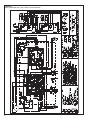
19.0 WIRING DIAGRAMS. . . . . . . . . . . . . . . . . . . . . . . . . . . . . . . . . . . . . . . . . . . . 49-50
2
1.0 SAFETY INFORMATION
! WARNING
THESE INSTRUCTIONS ARE INTENDED AS AN AID TO QUALIFIED, LICENSED
SERVICE PERSONNEL FOR PROPER INSTALLATION, ADJUSTMENT AND
OPERATION OF THIS UNIT. READ THESE INSTRUCTIONS THOROUGHLY
BEFORE ATTEMPTING INSTALLATION OR OPERATION. FAILURE TO FOLLOW THESE INSTRUCTIONS MAY RESULT IN IMPROPER INSTALLATION,
ADJUSTMENT, SERVICE OR MAINTENANCE POSSIBLY RESULTING IN FIRE,
ELECTRICAL SHOCK, PROPERTY DAMAGE, PERSONAL INJURY OR DEATH.
! WARNING
THE MANUFACTURER’S WARRANTY DOES NOT COVER ANY DAMAGE OR
DEFECT TO THE AIR CONDITIONER CAUSED BY THE ATTACHMENT OR USE
OF ANY COMPONENTS, ACCESSORIES OR DEVICES (OTHER THAN THOSE
AUTHORIZED BY THE MANUFACTURER) INTO, ONTO OR IN CONJUNCTION
WITH THE AIR CONDITIONER. YOU SHOULD BE AWARE THAT THE USE OF
UNAUTHORIZED COMPONENTS, ACCESSORIES OR DEVICES MAY
ADVERSELY AFFECT THE OPERATION OF THE AIR CONDITIONER AND MAY
ALSO ENDANGER LIFE AND PROPERTY. THE MANUFACTURER DISCLAIMS
ANY RESPONSIBILITY FOR SUCH LOSS OR INJURY RESULTING FROM THE
USE OF SUCH UNAUTHORIZED COMPONENTS, ACCESSORIES OR DEVICES.
! WARNING
DISCONNECT ALL POWER TO UNIT BEFORE STARTING MAINTENANCE.
FAILURE TO DO SO CAN CAUSE ELECTRICAL SHOCK RESULTING IN
SEVERE PERSONAL INJURY OR DEATH.
! WARNING
DO NOT USE OXYGEN TO PURGE LINES OR PRESSURIZE SYSTEM FOR
LEAK TEST. OXYGEN REACTS VIOLENTLY WITH OIL, WHICH CAN
CAUSE AN EXPLOSION RESULTING IN SEVERE PERSONAL INJURY OR
DEATH.
! WARNING
THE UNIT MUST BE PERMANENTLY GROUNDED. FAILURE TO DO SO
CAN CAUSE ELECTRICAL SHOCK RESULTING IN SEVERE PERSONAL
INJURY OR DEATH.
! WARNING
TURN OFF ELECTRIC POWER AT THE FUSE BOX OR SERVICE PANEL
BEFORE MAKING ANY ELECTRICAL CONNECTIONS.
ALSO, THE GROUND CONNECTION MUST BE COMPLETED BEFORE
MAKING LINE VOLTAGE CONNECTIONS. FAILURE TO DO SO CAN
RESULT IN ELECTRICAL SHOCK, SEVERE PERSONAL INJURY OR
DEATH.
Continued on next page ➜
3
! CAUTION
R-410A systems operate at higher pressures than R-22 systems. Do not use
R-22 service equipment or components on R-410A equipment.
! CAUTION
Only use evaporators approved for use on R-410A systems. Use of existing
R-22 evaporators can introduce mineral oil to the R-410A refrigerant forming two different liquids and decreasing oil return to the compressor. This
can result in compressor failure.
! CAUTION
When coil is installed over a finished ceiling and/or living area, it is
recommended that a secondary sheet metal condensate pan be
constructed and installed under entire unit. Failure to do so can result
in property damage.
! CAUTION
THE COMPRESSOR HAS AN INTERNAL OVERLOAD PROTECTOR. UNDER
SOME CONDITIONS, IT CAN TAKE UP TO 2 HOURS FOR THIS OVERLOAD
TO RESET. MAKE SURE OVERLOAD HAS HAD TIME TO RESET BEFORE
CONDEMNING THE COMPRESSOR.
! CAUTION
UNIT MAY START SUDDENLY AND WITHOUT WARNING
Solid red light indicates a thermostat call for unit operation is present at
the ICC control. ICC control will attempt to start unit after short cycle timer
expires or when in Active Protection mode will attempt to restart unit prior
to Lockout mode.
! CAUTION
UNIT MAY START SUDDENLY AND WITHOUT WARNING
Solid red light indicates a thermostat call for unit operation is present at the
ICC. ICC will attempt to start unit after short cycle timer expires or when in
Active Protection mode will attempt to restart unit prior to Lockout mode.
! CAUTION
THE TOP OF THE SCROLL COMPRESSOR SHELL IS HOT. TOUCHING THE
COMPRESSOR TOP MAY RESULT IN SERIOUS PERSONAL INJURY.
! CAUTION
R-410A PRESSURES ARE APPROXIMATELY 60% HIGHER THAN R-22
PRESSURES. USE APPROPRIATE CARE WHEN USING THIS REFRIGERANT. FAILURE TO EXERCISE CARE MAY RESULT IN EQUIPMENT DAMAGE, OR PERSONAL INJURY.
4
! WARNING
THE MANUFACTURER’S WARRANTY DOES NOT COVER ANY
DAMAGE OR DEFECT TO THE
AIR CONDITIONER CAUSED BY
THE ATTACHMENT OR USE OF
ANY COMPONENTS. ACCESSORIES OR DEVICES (OTHER
THAN THOSE AUTHORIZED BY
THE MANUFACTURER) INTO,
ONTO OR IN CONJUNCTION
WITH THE AIR CONDITIONER.
YOU SHOULD BE AWARE THAT
THE USE OF UNAUTHORIZED
COMPONENTS, ACCESSORIES
OR DEVICES MAY ADVERSELY
AFFECT
THE
OPERATION
OF THE AIR CONDITIONER AND
MAY ALSO ENDANGER LIFE
AND PROPERTY. THE MANUFACTURER
DISCLAIMS
ANY
RESPONSIBILITY FOR SUCH
LOSS OR INJURY RESULTING
FROM THE USE OF SUCH
UNAUTHORIZED COMPONENTS,
ACCESSORIES OR DEVICES.
MATCH ALL COMPONENTS:
• OUTDOOR UNIT
• INDOOR COIL/METERING DEVICE
• INDOOR AIR HANDLER/FURNACE
• REFRIGERANT LINES
2.0 GENERAL INFORMATION
The (-)ASL-series of condensing units are designed to operate using the Comfort
Control 2 System™ or traditional 24VAC controls. These units are equipped with the
Comfort Control 2. Your installation must have these components to use Comfort
Control 2 System™ :
• (-)ASL condensing unit equipped with the Comfort Control 2 System™
• An air handler or furnace equipped with the Comfort Control 2 System™
• A Comfort Control 2 thermostat
If your installation does not meet the above requirements, you must use traditional
24VAC controls.
This installation instruction manual contains complete instructions for installation
and setup using Comfort Control 2 or conventional 24VAC controls. Please refer to
the Engineering Specification Sheets for complete performance data, thermostat,
and accessory listings.
The information contained in this manual has been prepared to assist in the proper
installation, operation and maintenance of the air conditioning system. Improper
installation, or installation not made in accordance with these instructions, can result
in unsatisfactory operation and/or dangerous conditions (noise and component failure), and can cause the related warranty not to apply.
Read this manual and any instructions packaged with separate equipment required
to make up the system prior to installation. Retain this manual for future reference.
To achieve optimum efficiency and capacity, the indoor cooling coils listed in the
condensing unit specification sheet should be used.
2.1 CHECKING PRODUCT RECEIVED
Upon receiving unit, inspect it for any shipping damage. Claims for damage, either
apparent or concealed, should be filed immediately with the shipping company.
Check condensing unit model number, electrical characteristics and accessories to
determine if they are correct. Check system components (evaporator coil, condensing unit, evaporator blower, etc.) to make sure they are properly matched.
2.2 APPLICATION
Before specifying any air conditioning equipment, a survey of the structure and a
heat gain calculation must be made. A heat gain calculation begins by measuring
all external surfaces and openings that gain heat from the surrounding air and
quantifying that heat gain. A heat gain calculation also calculates the extra heat
load caused by sunlight and by humidity removal.
Air conditioning systems are sized on the cooling load calculation. There are two
capacities that enable the equipment to provide comfort. The first is sensible capacity.
Sensible heat is the heat energy measured on the dry bulb thermometer as it is
added or removed.
The second form of heat is called latent or hidden heat. This is heat held in the
humidity in the air.
A properly-sized unit removes both forms of heat, producing a comfortable living
space. An oversized system cycles on and off too quickly and does not properly
remove humidity, producing an uncomfortable living space. Select the indoor and
outdoor equipment combination based on the manufacturer’s engineering data.
After the equipment combination has been selected, satisfying both sensible and
latent conditioning requirements, the system must be properly installed. Only then
can the unit provide the comfort the manufacturer intends.
There are several factors that the installers must consider:
•
•
•
•
Outdoor unit location
System refrigerant charge
Indoor unit blower speed
System air balancing
•
•
•
•
Proper equipment evacuation
Indoor unit airflow
Supply and return air duct design and sizing
Diffuser and return air grille location and sizing
5
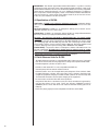
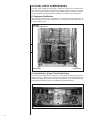
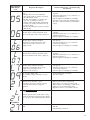
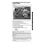
2.3 DIMENSIONS
UNIT MODEL NUMBER EXPLANATION
FIGURE 1
(-)ASL
DIMENSIONS AND INSTALLATION CLEARANCES
– 036 J E C
AIR AIR
DISCHARGE
DISCHARGE
ALLOW 600 [1524 mm] CLEARANCE
ALLOW 60"
[1524 mm] CLEARANCE
EC = EQUIPPED WITH THE
COMFORT CONTROL2 SYSTEM™
J - 208/230-1-60
(NOMINAL CAPACITY)
024 = 24000 BTU/HR
036 = 36000 BTU/HR
039 = 39000 BTU/HR
048 = 48000 BTU/HR
060 = 60000 BTU/HR
W
L
L = DESIGN SERIES (R-410A)
H
S = 18 SEER
A = REMOTE CONDENSING UNIT
TRADE NAME
BASE PAN
ACCESS
ACCESS
PANEL
PANEL
A-00002
AIR INLETS
AIR
INLETS
(LOUVERS)
ALLOW 120 [305 mm]
(LOUVERS)
MIN. CLEARANCE
ALLOW
6” [152 mm]
3 SIDES
MIN. CLEARANCE
3 SIDES
ALTERNATE HIGH VOLTAGE
CONNECTION (KNOCKOUT)
1 11/320 [34 mm]
ALTERNATE LINE VOLTAGE
ENTRY (KNOCKOUT)
111⁄32" [34 MM]
CONNECT THE LINE
VOLTAGE CONDUIT TO
THE BOTTOM OF THE
CONTROL BOX
ALLOW 240 [610 mm]
24" [610 mm]
ALLOW
ACCESS CLEARANCE
ACCESS CLEARANCE
LOWVOLTAGE
VOLTAGE
LINE
ENTRY
CONNECTION
7/78⁄8"" [22
[22 mm]
MM]
SERVICE
FITTINGS
VAPOR LINE
CONNECTION
LINE VOLTAGE ENTRY
" [34 MM]
111⁄32
HIGH
VOLTAGE
CONNECT THE LINE
CONNECTION
VOLTAGE
CONDUIT
mm] TO
111/32" [34
THE BOTTOM OF THE
CONTROL BOX
LIQUID LINE
CONNECTION
SERVICE ACCESS
TO ELECTRICAL &
27/8" [73 mm] DIA.
VALVES ALLOW
ACCESSORY
24" [610 mm]
KNOCKOUTS
CLEARANCE
ONE SIDE
BOTTOM VIEW SHOWING DRAIN OPENINGS
(\\\\\ SHADED AREAS).
SERVICE ACCESS
FOR 039, 048 & 060 MODELS
SERVICE
FITTING
SERVICE ACCESS
FOR 024 & 036 MODELS
VAPOR LINE
CONNECTION
LOW LINE
VOLTAGE 7⁄8"
LOW LINE
VOLTAGE 7⁄8"
HIGH LINE
VOLTAGE 11⁄4"
LIQUID LINE
CONNECTION
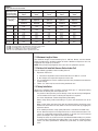
2.4 ELECTRICAL & PHYSICAL DATA
TABLE 1
(-)ASL-JEC ELECTRICAL DATA
ELECTRICAL
Phase
Frequency
(Hz)
Voltage
(Volts)
Model
Number
RASL-
Compressor
Rated Load Locked
Rotor
Amperes Amperes
(RLA)
(LRA)
PHYSICAL
Fan
Motor
Full Load
Amperes
(FLA)
Minimum
Circuit
Ampacity
Amperes
Minimum
Amperes
Maximum
Amperes
Outdoor Coil
Fuse or HACR
Circuit Breaker
Face Area
Sq. Ft. [m2]
No.
Rows
CFM [L/s}
Refrig.
Per
Circuit
Oz. [g]
Weight
Net
Lbs. [kg]
Shipping
Lbs. [kg]
236 [107]
263.5 [119.5]
Rev. 2/24/2010
6
024JEC
1-60-208/230
10.3/10.3
52
0.5
14/14
20/20
20/20
15.8 [1.47]
1
2500 [1038]
144 [4082]
036JEC
1-60-208/230
16.7/16.7
82
2.8
24/24
30/30
40/40
23.01 [2.14]
1
3400 [1321]
150 [4252]
039JEC
1-60-208/230
17.9/17.9
96
2.8
26/26
30/30
40/40
23 [2.14]
2
3500 [1321]
268 [7598]
326 [147.9]
345 [156.5]
048JEC
1-60-208/230
26.9/26.9
117
2.8
37/37
45/45
60/60
23 [2.14]
2
3500 [1321]
253 [7173]
326 [147.9]
348 [157.9]
060JEC
1-60-208/230
28.2/28.2
146
2.8
39/39
50/50
60/60
23 [2.14]
2
3500 [1321]
241 [6832]
328 [148.8]
346 [156.9]
250.5 [113.6] 314.5 [142.7]
2.5 PROPER INSTALLATION
Proper sizing and installation of this equipment is critical to achieve optimal performance. Use the information in this Installation Instruction Manual and reference the
applicable Engineering Specification Sheet when installing this product.
IMPORTANT: This product has been designed and manufactured to meet ENERGY STAR® criteria for energy efficiency when matched with appropriate coil components. However, proper refrigerant charge and proper airflow are critical to achieve
rated capacity and efficiency. Installation of this product should follow the manufacturer’s refrigerant charging and airflow instructions. Failure to confirm proper
charge and airflow may reduce energy efficiency and shorten equipment life.
3.0 LOCATING UNIT
3.1 Corrosive Environment
The metal parts of this unit may be subject to rust or deterioration if exposed to a
corrosive environment. This oxidation could shorten the equipment’s useful life.
Corrosive elements include, but are not limited to, salt spray, fog or mist in seacoast
areas, sulphur or chlorine from lawn watering systems, and various chemical contaminants from industries such as paper mills and petroleum refineries.
If the unit is to be installed in an area where contaminants are likely to be a problem, special attention should be given to the equipment location and exposure.
•
•
•
•
Avoid having lawn sprinkler heads spray directly on the unit cabinet.
In coastal areas, locate the unit on the side of the building away from the waterfront.
Shielding provided by a fence or shrubs may give some protection, but cannot
violate minimum airflow and service access clearances.
Elevating the unit off its slab or base enough to allow air circulation will help
avoid holding water against the basepan.
Regular maintenance will reduce the build-up of contaminants and help to protect
the unit’s finish.
! WARNING
DISCONNECT ALL POWER TO UNIT BEFORE STARTING
MAINTENANCE. FAILURE TO DO SO CAN CAUSE ELECTRICAL SHOCK
RESULTING IN SEVERE PERSONAL INJURY OR DEATH.
•
Frequent washing of the cabinet, fan blade and coil with fresh water will remove
most of the salt or other contaminants that build up on the unit.
•
Regular cleaning and waxing of the cabinet with a good automobile polish will
provide some protection.
•
A good liquid cleaner may be used several times a year to remove matter that
will not wash off with water.
Several different types of protective coatings are offered in some areas. These
coatings may provide some benefit, but the effectiveness of such coating materials
cannot be verified by the equipment manufacturer.
3.2 CONDENSER LOCATION
Consult local and national building codes and ordinances for special installation
requirements. Following location information will provide longer life and simplified
servicing of the outdoor condenser.
NOTE: These units must be installed outdoors. No ductwork can be attached, or
other modifications made, to the discharge grille. Modifications will affect performance or operation.
7
3.3 Operational Issues
•
•
•
•
IMPORTANT: Locate the unit in a manner that will not prevent, impair or compromise the performance of other equipment horizontally installed in proximity
to the unit. Maintain all required minimum distances to gas and electric meters,
dryer vents, exhaust and inlet openings. In the absence of National Codes, or
manufacturers’ recommendations, local code recommendations and requirements will take precedence.
Refrigerant piping and wiring should be properly sized and kept as short as
possible to avoid capacity losses and increased operating costs.
Locate the unit where water run off will not create a problem with the equipment. Position the unit away from the drip edge of the roof whenever possible.
Units are weatherized, but can be affected by the following:
o Water pouring into the unit from the junction of rooflines, without protective
guttering. Large volumes of water entering the heat pump while in operation
can impact fan blade or motor life, and coil damage may occur to a heat
pump if moisture cannot drain from the unit under freezing conditions.
o Freezing moisture, or sleeting conditions, can cause the cabinet to ice-over
prematurely and prevent heat pump operation, requiring backup heat, which
generally results in less economical operation.
Closely follow clearance recommendations on Page 6.
o 24” to the service panel access
o 60” above heat pump fan discharge (unit top) to prevent recirculation
o 6” to heat pump coil grille air inlets
3.4 For Units With Space Limitations
FOR CONDENSERS WITH SPACE LIMITATIONS
In the event that a space limitation exists, we will permit the following clearances:
Single Unit Applications: Clearances below 6 inches will reduce unit capacity and
efficiency. Do not reduce the 60-inch discharge, or the 24-inch service clearances.
Multiple Unit Applications: When multiple condenser grille sides are aligned, a 6inch per unit clearance is recommended, for a total of 12” between two units. Two
combined clearances below 12 inches will reduce capacity and efficiency. Do not
reduce the 60-inch discharge, or 24-inch service, clearances.
3.5 Customer Satisfaction Issues
•
•
The condensing unit should be located away from the living, sleeping and
recreational spaces of the owner and those spaces on adjoining property.
To prevent noise transmission, the mounting pad for the outdoor unit should not
be connected to the structure, and should be located sufficient distance above
grade to prevent ground water from entering the unit.
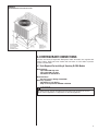
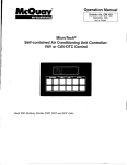
3.6 Unit Mounting
If elevating the condensing unit, either on a flat roof or on a slab, observe the
following guidelines.
•
The base pan provided elevates the heat pump 3/4” above the base pad.
•
If elevating a unit on a flat roof, use 4” x 4” (or equivalent) stringers positioned
to distribute unit weight evenly and prevent noise and vibration (see Figure 2).
NOTE: Do not block drain openings shown in Figure 1.
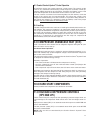
3.7 Factory-Preferred Tie-Down Method for Outdoor Units
IMPORTANT: The Manufacturer approved/recommended method is a guide to securing equipment for wind and seismic loads. Other methods might provide the same
result, but the Manufacturer method is the only one endorsed by Manufacturer for
securing equipment where wind or earthquake damage can occur. Additional information is available in the PTS (Product Technical Support) section of the Manufacturer
website Rheemote.net and can be found as a listing under each outdoor model. If you
do not have access to this site, your Distributor can offer assistance.
8
FIGURE 2
RECOMMENDED ELEVATED INSTALLATION
4.0 REFRIGERANT CONNECTIONS
All units are factory charged with Refrigerant 410A. All models are supplied with
service valves. Keep tube ends sealed until connection is to be made to prevent
system contamination.
4.1 Tools Required For Installing & Servicing R-410A Models
Manifold Sets:
-Up to 800 PSIG High side
-Up to 250 PSIG Low Side
-550 PSIG Low Side Retard
Manifold Hoses:
-Service Pressure Rating of 800 PSIG
Recovery Cylinders:
-400 PSIG Pressure Rating
-Dept. of Transportation 4BA400 or BW400
! CAUTION
R-410A systems operate at higher pressures than R-22 systems. Do not use
R-22 service equipment or components on R-410A equipment.
9
IMPORTANT: The Rheem approved/recommended method is a guide to securing
equipment for wind and seismic loads. Other methods might provide the same result,
but the Rheem method is the only one endorsed by Rheem for securing equipment
where wind or earthquake damage can occur. Additional information is available in
the PTS (Product Technical Support) section of the Rheem website Rheemote.net
and can be found as a listing under each outdoor model. If you do not have access
to this site, your Distributor can offer assistance.
4.2 Specifications of R-410A:
Application: R-410A is not a drop-in replacement for R-22; equipment designs
must accommodate its higher pressures. It cannot be retrofitted into R-22 heat
pumps.
Physical Properties: R-410A has an atmospheric boiling point of -62.9°F and its
saturation pressure at 77°F is 224.5 psig.
Composition: R-410A is an azeotropic mixture of 50% by weight difluoromethane
(HFC-32) and 50% by weight pentafluoroethane (HFC-125).
Pressure: The pressure of R-410A is approximately 60% (1.6 times) greater
than R-22. Recovery and recycle equipment, pumps, hoses and the like need to
have design pressure ratings appropriate for R-410A. Manifold sets need to range
up to 800 psig high-side and 250 psig low-side with a 550 psig low-side retard.
Hoses need to have a service pressure rating of 800 psig. Recovery cylinders need
to have a 400 psig service pressure rating. DOT 4BA400 or DOT BW400.
Combustibility: At pressures above 1 atmosphere, mixture of R-410A and air can
become combustible. R-410A and air should never be mixed in tanks or supply
lines, or be allowed to accumulate in storage tanks. Leak checking should
never be done with a mixture of R-410A and air. Leak checking can be performed safely with nitrogen or a mixture of R-410A and nitrogen.
4.3 Quick Reference Guide For R-410A
• R-410A refrigerant operates at approximately 60% higher pressure (1.6 times)
than R-22. Ensure that servicing equipment is designed to operate with R-410A.
• R-410A refrigerant cylinders are pink in color.
• R-410A, as with other HFC’s is only compatible with POE oils.
• Vacuum pumps will not remove moisture from oil.
• R-410A systems are to be charged with liquid refrigerants. Prior to March 1999,
R-410A refrigerant cylinders had a dip tube. These cylinders should be kept
upright for equipment charging. Post March 1999 cylinders do not have a dip tube
and should be inverted to ensure liquid charging of the equipment.
• Do not install a suction line filter drier in the liquid line.
• A liquid line filter drier is standard on every unit. Only manufacturer approved liquid line filter driers can be used. These are Sporlan (CW083S) and Alco
(80K083S) driers. These filter driers are rated for minimum working pressure of
600 psig.
• Desiccant (drying agent) must be compatible for POE oils and R-410A.
10
5.0 REPLACEMENT UNITS
To prevent failure of a new condensing unit, the existing evaporator tubing system
must be correctly sized and cleaned or replaced. Care must be exercised that the
expansion device is not plugged. For new and replacement units, a liquid line filter
drier should be installed and refrigerant tubing should be properly sized. Test the oil
for acid. If positive, a suction line filter drier is mandatory.
IMPORTANT: WHEN REPLACING AN R-22 UNIT WITH AN R-410A UNIT,
EITHER REPLACE THE LINE SET OR ENSURE THAT THE EXISTING LINE SET
IS THOROUGHLY CLEANED OF ANY OLD OIL OR DEBRIS.
6.0 INDOOR COIL
REFER TO INDOOR COIL MANUFACTURER’S INSTALLATION INSTRUCTIONS.
IMPORTANT: The manufacturer is not responsible for the performance and operation of a mismatched system, or for a match listed with another manufacturer’s coil.
NOTE: All (-)ASL units must be installed with a TXV Evaporator.
! CAUTION
Only use evaporators approved for use on R-410A systems. Use of existing R-22
evaporators can introduce mineral oil to the R-410A refrigerant forming two different liquids and decreasing oil return to the compressor. This can result in compressor failure.
The thermostatic expansion valve is specifically designed to operate with R-410A.
DO NOT use an R-22 TXV or evaporator. The existing evaporator must be
replaced with the factory specified TXV evaporator specifically designed for
R-410A.
6.1 Location
Do not install the indoor coil in the return duct system of a gas or oil furnace.
Provide a service inlet to the coil for inspection and cleaning. Keep the coil pitched
toward the drain connection.
! CAUTION
When coil is installed over a finished ceiling and/or living area, it is
recommended that a secondary sheet metal condensate pan be
constructed and installed under entire unit. Failure to do so can result
in property damage.
7.0 INTERCONNECTING TUBING
7.1 Vapor and Liquid Lines
Keep all lines sealed until connection is made.
Make connections at the indoor coil first.
Refer to Line Size Information in Tables 3, 4, 5 and 6 for correct size and multipliers
to be used to determine capacity for various vapor line diameters and lengths of run.
The losses due to the lines being exposed to outdoor conditions are not included.
The factory refrigeration charge in the outdoor unit is sufficient for 15 feet of interconnecting lines. The factory refrigeration charge in the outdoor unit is sufficient for
the unit and 15 feet of standard size interconnecting liquid and vapor lines. For different lengths, adjust the charge as indicated below.
1/4” ± .3 oz. per foot
5/16” ± .4 oz. per foot
3/8” ± .6 oz. per foot
1/2” ± 1.2 oz. per foot
11
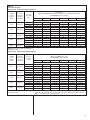
TABLE 3
VAPOR LINE CAPACITY MULTIPLIER
(-)ASL
Unit Vapor Line
Connection Size
(inches I.D.) [mm]
024
036
039
048
060
3/4” [19.05] I.D.
Sweat
3/4” [19.05] I.D.
Sweat
3/4” [19.05] I.D.
Sweat
3/4” [19.05] I.D.
Sweat
7/8” [22.23] I.D.
Sweat
Vapor Line Diameter (inches O.D.) [mm]
Vapor Line Run
Feet [m]
25‘ [7.62]
50’ [15.24]
75’ [22.86]
100’ [30.48]
125’ [38.10]
150’ [45.72]
Opt.
Std.
Opt.
Std.
Opt.
Std.
Opt.
Std.
Opt.
Std.
Opt.
Std.
5/8” [15.88]
Optional
5/8” [15.88]
Optional
5/8” [15.88]
Optional
5/8” [15.88]
Optional
3/4” [19.05]
Optional
3/4” [19.05]
Standard
3/4” [19.05]
Standard
3/4” [19.05]
Standard
3/4” [19.05]
Standard
7/8” [22.23]
Standard
1.00
1.00
0.98
1.00
0.98
1.00
0.98
N/A
0.96
N/A
0.96
N/A
0.99
1.00
0.98
1.00
0.96
0.99
0.95
N/A
0.94
N/A
0.92
N/A
NOTES:
1. Do NOT exceed the limits in the liquid and suction line sizing charts.
2. Do NOT use 7/8 OD suction lines in 2 or 4-ton applications.
3. Do NOT use 1-1/8 OD suction line in ANY application.
4. Line sets over 75 feet MUST use the optional suction line.
0.99
1.00
0.97
0.99
0.96
0.99
0.95
N/A
0.93
N/A
0.91
N/A
0.98
1.00
0.96
0.99
0.94
0.98
0.92
N/A
0.90
N/A
0.88
N/A
0.99
1.00
0.98
0.99
0.96
0.99
0.95
N/A
0.94
N/A
0.93
N/A
7.2 Maximum Length of Lines
The maximum length of interconnecting line is 150 feet. Always use the shortest
length possible with a minimum number of bends. Additional compressor oil is not
required for any length up to 150 feet.
NOTE: Excessively long refrigerant lines cause loss of equipment capacity.
7.3 Outdoor Unit Installed Above or Below Indoor Coil
Use the following guidelines when installing the unit:
1. Expansion Valve Coil:
a. The vertical separation cannot exceed the value in Tables 4, 5, and 6.
b. No changes are required for expansion valve coils.
2. It is recommended to use the smallest liquid line size permitted to minimize the
system charge.
3. Tables 4, 5, and 6 may be used for sizing horizontal runs.
7.4 Tubing Installation
Observe the following when installing correctly sized type “L” refrigerant tubing
between the condensing unit and evaporator coil:
•
•
•
•
•
•
•
12
If a portion of the liquid line passes through a hot area where liquid refrigerant
can be heated to form vapor, insulating the liquid line is required.
Use clean, dehydrated, sealed refrigeration grade tubing.
Always keep tubing sealed until tubing is in place and connections are to be
made.
Blow out the liquid and vapor lines with dry nitrogen before connecting to the
outdoor unit and indoor coil. Any debris in the line set will end up plugging the
expansion device.
As an added precaution, a high quality filter drier is standard on R-410A units.
Do not allow the vapor line and liquid line to be in contact with each other. This
causes an undesirable heat transfer resulting in capacity loss and increased
power consumption. The vapor line must be insulated.
If tubing has been cut, make sure ends are deburred while holding in a position
to prevent chips from falling into tubing. Burrs such as those caused by tubing
cutters can affect performance dramatically, particularly on small liquid line
sizes.
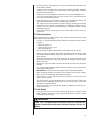
TABLE 4
(-)ASL LIQUID LINE SIZING
LIQUID LINE SIZE - OUTDOOR UNIT ABOVE INDOOR COIL
R-410A
System
Capacity
Model
Line Size
Connection
Size (Inch
I.D.) [mm]
-024
3/8” [9.53]
-036
3/8” [9.53]
-039
3/8” [9.53]
-048
3/8” [9.53]
-060
3/8” [9.53]
Line Size
(Inch O.D.)
[mm]
Liquid Line Size
Outdoor Unit Above Indoor Coil (Cooling Only - Does not apply to Heat Pumps)
Total Equivalent Length - Feet [m]
25 [7.62]
50 [15.24]
75 [22.86]
100 [30.48]
125 [38.1]
150 [45.72]
0
0
0
0
0
0
0
0
0
0
0
0
0
0
0
0
0
0
0
0
0
0
0
0
0
0
0
0
10 [3.05]
0
0
6 [1.83]
0
0
0
0
0
0
0
0
0
0
34 [10.36]
0
0
14 [4.27]
0
0
0
0
0
18 [5.49]
0
0
0
0
58 [17.68]
0
0
21 [6.40]
0
0
10 [3.05]
0
0
40 [12.19]
0
0
0
0
82 [24.99]
0
0
28 [8.53]
0
0
24 [7.32]
0
0
62 [18.90]
0
0
0
0
1/4” [6.35]*
5/16” [7.93]
3/8” [9.52]
5/16” [7.93]
3/8” [9.52]*
1/2” [12.70]
5/16” [7.93]*
3/8” [9.52]
1/2” [12.70]
5/16” [7.93]*
3/8” [9.52]
1/2” [12.70]
3/8” [9.52]*
1/2” [12.70]
NOTES: N/A = Application Not Recommended
*Standard Line Size
Minimum Vertical Separation - Feet [m]
LIQUID LINE SIZE - OUTDOOR UNIT BELOW INDOOR COIL
R-410A
System
Capacity
Model
Line Size
Connection
Size (Inch
I.D.) [mm]
-024
3/8” [9.53]
-036
3/8” [9.53]
-039
3/8” [9.53]
-048
3/8” [9.53]
-060
3/8” [9.53]
Line Size
(Inch O.D.)
[mm]
1/4” [6.35]*
5/16” [7.93]
3/8” [9.52]
5/16” [7.93]
3/8” [9.52]*
1/2” [12.70]
5/16” [7.93]*
3/8” [9.52]
1/2” [12.70]
5/16” [7.93]*
3/8” [9.52]
1/2” [12.70]
3/8” [9.52]*
1/2” [12.70]
NOTES: N/A = Application Not Recommended
*Standard Line Size
25 [7.62]
50 [15.24]
25 [11.28]
25 [14.33]
25 [15.24]
N/A
12 [3.66]
14 [4.27]
15 [4.57]
18 [5.49]
20 [6.10]
25 [10.36]
25 [11.89]
25 [12.50]
25 [11.28]
25 [11.89]
13 [3.96]
44 [13.41]
48 [14.63]
N/A
9 [2.74]
13 [3.96]
11 [3.35]
17 [5.18]
19 [5.79]
24 [7.32]
36 [10.97]
40 [12.19]
33 [10.06]
39 [11.89]
Liquid Line Size
Outdoor Unit Below Indoor Coil
Total Equivalent Length - Feet [m]
75 [22.86]
100 [30.48]
125 [38.1]
150 [45.72]
N/A
40 [12.19]
47 [14.33]
N/A
N/A
13 [3.96]
N/A
15 [4.57]
19 [5.79]
N/A
34 [10.36]
40 [12.19]
30 [9.14]
38 [11.58]
N/A
36 [10.97]
46 [14.02]
N/A
N/A
12 [3.66]
N/A
13 [3.96]
19 [5.79]
N/A
32 [9.75]
39 [11.89]
25 [7.62]
37 [11.28]
N/A
30 [9.14]
45 [13.72]
N/A
N/A
12 [3.66]
N/A
12 [3.66]
18 [5.49]
N/A
29 [8.84]
39 [11.89]
15 [4.57]
37 [11.28]
N/A
24 [7.32]
43 [13.11]
N/A
N/A
11 [3.35]
N/A
10 [3.05]
18 [5.49]
N/A
23 [7.01]
38 [11.58]
N/A
36 [10.97]
Maximum Vertical Separation - Feet [m]**
**Maximum vertical separation listed in table can be exceeded if system is charged to 8°-10°F
liquid subcooling level at the indoor coil. A gauge port must be added to the liquid line near the
indoor coil to measure subcooling at that point.
13
TABLE 5
(-)ASL SUCTION LINE SIZING
SUCTION LINE SIZE - OUTDOOR UNIT ABOVE INDOOR COIL
R-410A
System
Capacity
Model
Line Size
Connection
Size (Inch
I.D.) [mm]
-024
3/4” [19.05]
-036 & -039
3/4” [19.05]
-048
7/8” [22.22]
-060
7/8” [22.22]
Line Size
(Inch O.D.)
[mm]
5/8” [15.88]
3/4” [19.05]*
7/8” [22.23]
5/8” [15.88]
3/4” [19.05]*
7/8” [22.23]
5/8” [15.88]
3/4” [19.05]*
7/8” [22.23]
3/4” [19.05]
7/8” [22.23]*
1-1/8” [28.58]
Suction Line Size
Outdoor Unit ABOVE Indoor Coil (Cooling Only - Does not apply to Heat Pumps)
25 [7.62]
50 [15.24]
NOTES: Using suction line larger than shown in chart will result in poor oil return.
N/A = Application Not Recommended
*Standard Line Size
Total Equivalent Length - Feet [m]
75 [22.86]
100 [30.48]
Same as Liquid Line Size Table
NA
NA
Same as Liquid Line Size Table
NA
NA
Same as Liquid Line Size Table
Same as Liquid Line Size Table
NA
Same as Liquid Line Size Table
NA
NA
125 [38.1]
150 [45.72]
SUCTION LINE SIZE - OUTDOOR UNIT BELOW INDOOR COIL
R-410A
System
Capacity
Model
Line Size
Connection
Size
(Inch I.D.)
[mm]
-024
3/4” [19.05]
-036 & -039
3/4” [19.05]
-048
7/8” [22.22]
-060
7/8” [22.22]
Line Size
(Inch O.D.)
[mm]
5/8” [15.88]
3/4” [19.05]*
7/8” [22.23]
5/8” [15.88]
3/4” [19.05]*
7/8” [22.23]
5/8” [15.88]
3/4” [19.05]*
7/8” [22.23]
3/4” [19.05]
7/8” [22.23]*
1-1/8” [28.58]
Suction Line Size
Outdoor Unit BELOW Indoor Coil (Cooling Only - Does not apply to Heat Pumps)
25 [7.62]
50 [15.24]
75 [22.86]
100 [30.48]
Same as Liquid Line Size Table
Same as Liquid Line Size Table
NA
Same as Liquid Line Size Table
Same as Liquid Line Size Table
NA
Same as Liquid Line Size Table
Same as Liquid Line Size Table
Same as Liquid Line Size Table
Same as Liquid Line Size Table
Same as Liquid Line Size Table
NA
NOTES: Using suction line larger than shown in chart will result in poor oil return.
N/A = Application Not Recommended
*Standard Line Size
14
Total Equivalent Length - Feet [m]
125 [38.1]
NA
NA
150 [45.72]
•
•
•
•
•
•
•
For best operation, keep tubing run as short as possible with a minimum number of elbows or bends.
Locations where the tubing will be exposed to mechanical damage should be
avoided. If it is necessary to use such locations, the copper tubing should be
housed to prevent damage.
If tubing is to be run underground, it must be run in a sealed watertight chase.
Use care in routing tubing and do not kink or twist. Use a good tubing bender
on the vapor line to prevent kinking.
Route the tubing using temporary hangers, then straighten the tubing and
install permanent hangers. Line must be adequately supported.
The vapor line must be insulated to prevent dripping (sweating) and prevent
performance losses. Armaflex and Rubatex are satisfactory insulations for this
purpose. Use 1/2” minimum insulation thickness, additional insulation may be
required for long runs.
Check Table 3 for the correct vapor line size. Check Table 4 for the correct liquid line size.
7.5 Tubing Connections
Indoor coils have only a holding charge of dry nitrogen. Keep all tube ends sealed
until connections are to be made.
•
Use type “L” copper refrigeration tubing. Braze the connections with the following alloys:
– copper to copper - 5%
– Silver alloy (no flux)
– copper to steel or brass - 35%
– silver alloy (with flux)
•
Be certain both refrigerant shutoff valves at the outdoor unit are closed.
•
Clean the inside of the fittings and outside of the tubing with steel wool or sand
cloth before soldering. Always keep chips, steel wool, dirt, etc., out of the inside
when cleaning.
•
Assemble tubing part way into fitting. Apply flux all around the outside of the
tubing and push tubing into stop. This procedure will keep the flux from getting
inside the system.
•
Remove the cap and schrader core from service port to protect seals from heat
damage.
•
Use an appropriate heatsink material around the copper stub and the service
valves before applying heat.
•
IMPORTANT: Do not braze any fitting with the TEV sensing bulb attached.
•
Braze the tubing between the outdoor unit and indoor coil. Flow dry nitrogen
into a service port and through the tubing while brazing.
•
After brazing – use an appropriate heatsink material to cool the joint and
remove any flux residue.
•
The service valves are not backseating valves. To open the valves, remove the
valve cap with an adjustable wrench. Insert a 3/16” or 5/16” hex wrench into the
stem. Back out counterclockwise.
•
Replace the valve cap finger tight then tighten an additional 1/2 hex flat for a
metal-to-metal seal.
7.6 Leak Testing
•
Pressurize line set and coil through service fittings with dry nitrogen to 150
PSIG maximum. Leak test all joints using liquid detergent. If a leak is found,
recover pressure and repair.
! WARNING
DO NOT USE OXYGEN TO PURGE LINES OR PRESSURIZE SYSTEM FOR
LEAK TEST. OXYGEN REACTS VIOLENTLY WITH OIL, WHICH CAN
CAUSE AN EXPLOSION RESULTING IN SEVERE PERSONAL INJURY OR
DEATH.
15
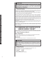
8.0 DUAL DRIVE COMPRESSORS
The -039, -048, & -060 condensing units contain two compressors to deliver maximum efficiency and comfort. The Dual Drive Compressors are sized to increase run
times at first stage operation (partial capacity). When additional capacity is needed,
a two stage thermostat energizes both compressors to deliver full rated capacity.
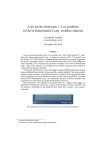
8.1 Compressor Identification
The individual compressors are identified as Compressor A and Compressor B.
When facing the access panel, Compressor A is on the left and Compressor B is on
the right. (See Figure 4.)
FIGURE 4
DUAL DRIVE COMPRESSORS
COMPRESSOR A
8.2 Comfort Control 2 System™ Control Identification
COMPRESSOR B
The Dual Drive condensing units use one (1) serial communicating control per compressor. There is a label in the control box that identifies each control/compressor
combination. When facing the access panel, Compressor A is controlled by the lefthand board and Compressor B is controlled by the right-hand board.
FIGURE 5
16
8.3 Comfort Control 2 System™ Control Operation
A Dual Drive unit has two controls instead of a single control. The controls are the
same as any residential communicating control except the secondary control dipswitches (SW5) should be in the off position. Therefore, the features such as fault
recall and the operation of the test button are the same as any JEC control.
The two controls are identical and interchangeable, but the memory cards that
attach to the controls are not interchangeable. This allows the controls to be
swapped for troubleshooting if one of the controls is suspected of being defective. If
the controls are swapped, it is important to keep the memory cards in the proper
locations. Do not cut the tethers on the memory cards!
8.4 Lead/Lag
Tandem compressor ASL units now have a Lead/Lag functionality built into the control software. The purpose of Lead/Lag is to average the runtime of the compressors to give the homeowner the greatest compressor life possible. Upon receiving a
first stage call, the primary compressor control (the control on the left as you face
the control box) will alternate which compressor services the call. An example of
Lead/Lag is: if compressor A is energized on one first stage call, compressor B
would normally service the next first stage call.
9.0 COMPRESSOR CRANKCASE HEAT (CCH)
CCH is standard on these models due to refrigerant migration during the off cycle
that can result in a noisy start up.
Crankcase Heater Operation:
Supplemental Crankcase heat is required to prevent refrigerant migration in systems with relatively high system refrigerant charges. Each Dual Drive compressor
has its own crankcase heater.
The crankcase heater control is integrated into the Comfort Control 2 System™ and
is designed for maximum energy savings.
Summary of operation:
• The crankcase heater is off whenever the compressor is running.
• Once the compressor turns off, the crankcase heater control (CCH) begins the
two-hour timer countdown.
• If the compressor stays off for two hours, the CCH turns on the crankcase heater.
All heaters are located on the lower half of the compressor shell. Its purpose is to
drive refrigerant from the compressor shell during long off cycles, thus preventing
damage to the compressor during start-up.
At initial start-up or after extended shutdown periods, make sure the heater is energized for at least 12 hours before the compressor is started. (Disconnect switch on
and wall thermostat off.)
10.0 HARD START COMPONENTS
Factory-installed start components are standard on all models.
11.0 HIGH AND LOW PRESSURE CONTROLS
10.0 (HPC AND LPC)
These controls keep the compressor from operating in pressure ranges which can
cause damage to the compressor. Both controls are in the low voltage control circuit.
High pressure control (HPC) is an automatic-reset which opens near 610 PSIG and
closes near 420 PSIG.
The low pressure control (LPC) is an automatic-reset which opens near 50 PSIG
and closes near 95 PSIG.
NOTE: HPC and LPC are monitored by the Comfort Control 2 System™. See
Section 12.0.
17
! CAUTION
THE COMPRESSOR HAS AN INTERNAL OVERLOAD PROTECTOR. UNDER
SOME CONDITIONS, IT CAN TAKE UP TO 2 HOURS FOR THIS OVERLOAD
TO RESET. MAKE SURE OVERLOAD HAS HAD TIME TO RESET BEFORE
CONDEMNING THE COMPRESSOR.
11.1 Evacuation Procedure
Evacuation is the most important part of the entire service procedure. The life and
efficiency of the equipment is dependent upon the thoroughness exercised by the
serviceman when evacuating air and moisture from the system.
Air in the system causes high condensing temperatures and pressure, resulting in
increased power input and non-verifiable performance.
COMFORT CONTROL2 SYSTEM™ CONTROL WIRING
Moisture chemically reacts with the refrigerant and oil to form corrosive hydrofluoric
and hydrochloric acids. These attack motor windings and parts, causing breakdown.
After the system has been leak checked and proven sealed, connect the vacuum
pump and evacuate system to 500 microns. The vacuum pump must be connected
to both the high and low sides of the system through adequate connections. Use
the largest size connections available since restrictive service connections may lead
to false readings because of pressure drop through the fittings.
IMPORTANT: Compressors (especially scroll type) should never be used to evacuate the air conditioning system because internal electrical arcing may result in a
damaged or failed compressor.
With thermostat in the “Off” position, turn the power on to the furnace and the heat
pump. Start the heat pump and the furnace with the thermostat. Make sure the
blower is operating.
12.0 CONDENSING UNITS EQUIPPED WITH THE
11.0 COMFORT CONTROL2 SYSTEM™
Comfort Control 2 is the next generation of the Integrated Compressor Control (ICC)
and is an integral part of the Comfort Control 2 System™ with the following features:
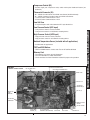
12.1 Control Description (see Figure 4)
Dual 7-Segment LED
• Displays status and diagnostic codes (See Status and Diagnostic Description)
• Displays diagnostic/fault recall (See Test Mode/Fault Recall)
Red LED (Y1)
• Y1 red LED (solid on) indicates Y1 call from thermostat is present
! CAUTION
UNIT MAY START SUDDENLY AND WITHOUT WARNING
Solid red light indicates a thermostat call for unit operation is present at
the ICC control. ICC control will attempt to start unit after short cycle timer
expires or when in Active Protection mode will attempt to restart unit prior
to Lockout mode.
Line Voltage Connector
• Line voltage is connected to control board at lug terminals L1 & L2
• Maximum wire size accepted is 6 AWG copper wire
• # 4 – 6 AWG
45 in/lbs
# 8 AWG
40 in/lbs
# 10 – 14 AWG 35 in/lbs
(Check wire terminations annually)
18
Compressor Control (K2)
• Sealed single pole compressor relay switch with optical feedback feature (arc
detection)
Thermostat Connector (E2)
•
•
•
•
R – 24VAC from the indoor unit 24VAC transformer (40 VA minimum)
C – 24VAC Common from the indoor unit 24VAC transformer
1-Data: System Communications Line 1
2-Data: System Communications Line 2
Low Volt Fuse
• If required replace with 3 A automotive ATC style blade fuse
Low Pressure Control (LPC Input)
COMFORT CONTROL2 SYSTEM™ CONTROL WIRING
• Low-pressure control is factory installed
• Low pressure control is an automatic resetting device
High Pressure Control (HPC Input)
• High-pressure control is factory installed
• High pressure control is an automatic resetting device
Ambient Temperature Sensor (included with all applications)
• Included with all applications
TEST and SW2 Buttons
• TEST and SW2 buttons used to enter Test and Fault Recall Mode
Memory Card
• The memory card stores all unit information.
• The unit information is called shared data.
• The shared data is all the information needed for proper unit operation.
LOW PRESSURE CONTROL INPUT
FIGURE 6
COMFORT CONTROL2 BOARD
O.D. FAN (OFM) RELAY
HIGH PRESSURE CONTROL INPUT
MEMORY CARD
LOW VOLT FUSE
THERMOSTAT
CONNECTION (E2)
COMPRESSOR
WIRING
CONNECTOR
{
RED LED (Y1)
LINE VOLTAGE
CONNECTION
AMBIENT DEFROST
CONTROL
DEFROST SENSOR
COMPRESSOR
CONTROL (K2)
ICC (INTEGRATED
COMPRESSOR CONTROL)
SW2 BUTTON
TEST BUTTON
7-SEGMENT LED
19
12.2 Comfort Control 2 System™ Control Wiring
COMFORT CONTROL2 SYSTEM™ CONTROL WIRING
An HVAC system equipped with Comfort Control 2 System™ consists of:
• Heat pump or condensing unit equipped with Comfort Control 2
• Air handler or furnace equipped with Comfort Control 2
• Comfort Control 2 thermostat
The four 18AWG low voltage control wires must be installed from the thermostat to
the indoor unit and from indoor unit to the outdoor unit. The wire length between the
thermostat and indoor unit should not be greater than 100 feet. The wire length
between the indoor unit and outdoor unit should not be greater than 125 feet.
IMPORTA NT: If the installed system does not meet these requirements, the system must be wired using traditional control wiring, reference Section 12.7
Conventional 24VAC Thermostat Control Wiring.
Serial communications require four (4) control wires for unit operation:
R – 24VAC
C – 24VAC common
1 – Data wire 1
2 – Data wire 2
No t e: Comfort Control 2 System™ requires 18 AWG thermostat wire.
No t e: TERM dipswitches should be in ON position.
FIGURE 7
TYPICAL COMFORT CONTROL2 SYSTEM™ WIRING DIAGRAM
Communicating Thermostat
1
Indoor Unit
2
R
C
Outdoor Unit
1
1
2
2
R
R
C
C
WIRING INFORMATION
Line Voltage
–Field Installed - - - - - –Factory Standard
If the low voltage control wiring is run in conduit with the power supply, Class I insulation is required. Class II insulation is required if run separate. Low voltage wiring
may be run through the insulated bushing provided in the 7/8 hole in the base
panel, up to and attached to the pigtails from the bottom of the control box. Conduit
can be run to the base panel if desired by removing the insulated bushing.
The serial communicating air handler or serial communicating furnace transformer
is equipped with a 24 volt, 50 VA transformer for proper system operation. See the
wiring diagram in Figure 5 for reference.
12.3 Comfort Control 2 System™ Diagnostic Codes in Dual Drive
12.3 Condensing Units
Comfort Control 2 System™ controls for both compressors are connected to the serial communicating network via Data Wire 1 and Data Wire 2. Each Comfort Control 2
System™ control board maintains separate fault history for the compressor it controls. Fault codes for both compressors can be retrieved using a service tool or via
the installer menus.
20
13.X Serial Communication ICC Control Operation
12.4 Comfort Control 2 ICC Control Operation
Installation Verification
In s t al l at i o n Ver i f i c at i o n
• 24V AC power
be present
the ICC
forICC
it to
• 24Von
ACR&C
powermust
on R&C
must be at
present
at the
foroperate
it to operate
• Line voltage
mustvoltage
be present
at present
the ICCatfor
and the
outdoor
fan fan
to operate
• Line
must be
thethe
ICCcompressor
for the compressor
and
the outdoor
to operate
• The ICC displays
a “0” for standby mode. Standby mode indicates line voltage and 24VA
a “0”isfornot
standby
mode. Standby
indicates
linethe
voltage
are present •atThe
theICC
ICCdisplays
and there
a command
for unitmode
operation
from
serial
and 24VAC are present at the ICC and there is not a command for unit operation
communicating
fromthermostat.
the serial communicating thermostat.
Zero (0) displayed
The
unit
in standby
Zero
(0)is displayed
The unit is in standby
2 SYSTEM™
SERIAL CONTROL
COMMUNICATIONS
CONTROL
WIRING
COMFORT
CONTROL
WIRING
Co m m an d f o r Co m p r es s o r Op er at i o n (Y1 L ED)
Command for •Compressor
Operation (Y1 LED)
If a command for compressor operation is received by the ICC (first stage/second
• If a commandstage
for compressor
is received
by thethe
ICC
stage/second
stage
cooling or firstoperation
stage/second
stage heating),
red(first
Y1 LED
will illuminate.
• The
ICCorhas
a built
3-minute
time
delay
compressor
to protect
the
cooling
first
stage/second
stage
heating),
the (1)
redsecond
Y1
LED
willoperations
illuminate.
• The
ICCin
has
an on/off
fan
delay
of between
one
for each
stage
of heating
or
• The ICC has a
in 3-minute
delay
compressor
operations
protect
the
cooling.
short
7-segment
willstage
flash
“C”,toor
“h1”,
or “h2
• compressor
The ICC hasagainst
anbuilt
on/off
fancycling.
delaytime
ofThe
one
(1) between
secondLEDs
for
each
of“c”,
heating
cooling.
compressor
cycling.
7-segment
LEDs
will
flash
“c”,
“h1”, or
“h2
•against
The
ICC
ignores
the
low The
pressure
control
the
90
seconds
compressor
the ignores
short
cycle
timer
is
active
and
a command
for first
unit
operation
is“C”,
received.
• while
The ICC
theshort
lower
pressure
control
for thefor
first
90
seconds
of of
compressor
operatio
operation.
while the short cycle timer is active and a command for unit operation is received.
• On heat pumps, the ICC ignores the LPC during the defrost cycle.
• The dual 7-segment LED displays five (5) operational status codes.
• The 7-segment LED can display five (5) codes during a command for unit operation:
1) Fi r st St ag e Co ol in g Oper at i on – When the ICC receives a command for first
Flashing
lower
case
c “c” is displayed on the dual 7-segment LEDs.
stage cooling
operation,
a lower
case
Flashing
lower
case
c
command –for
first stage
cooling
has abeen
received
1) First Stage CoolingAOperation
When
the ICC
receives
command
for first stage
command
forisfirst
stage cooling
been received
cooling operation, a A
lower
case “c”
displayed
on the has
7-segment
LEDs.
Lower case “c” indicates first stage cooling operation
2) Sec o n d St ag e Co o l i n g Op er at i o n – When the ICC receives a command for
second stage cooling operation, an upper case “C” is displayed on the dual 7segment LEDs.
Flashing upper case C
Flashing
upper
C stage cooling has be received
A command
forcase
second
A command for second stage cooling has be received
Upper case “C” indicates second stage cooling operation
3-m i n u t e A n t i -s h o r t Cy c l e Ti m er
• The ICC has a built in 3-minute
timelower
delay between
compressor
operations to
Flashing
case h and
1
protect the compressor against
short
cycling.
The
dual
7-segment
LEDs will flash
Flashing
lower
case
h
and
1
A command
for first
heating
received
“c” or “C” while the short cycle
timer is active
and stage
a command
for has
unit been
operation
is
A command for first stage heating has been received
received.
Lower case “c” indicates first stage cooling operation
Flashing lower case c
A command
for first stage
coolingstage
has been received
2) Second Stage Cooling Operation – When the ICC receives
a command
for second
cooling operation, an upper case “C” is displayed on the 7-segment LEDs.
Lower case “c” indicates first stage cooling operation
Flashing lower case h and 2
Flashing
h and
2 heating has been received
Flashing upper
C lower
A case
command
forcase
second
stage
2) Second Stage Cooling Operation – When the ICC receives
a command
for
second
stage
A command
for
second
stage
cooling
has
been
receivedhas been received
A command for second stage heating
cooling operation, an upper case “C” is displayed on the 7-segment LEDs.
• Thestage
3-minute
time delay
can be bypassed when a command for compressor
Upper case “C” indicates second
cooling
operation
operation is present by pressing the TEST button for 1 second and releasing. The
begin
operation and
theadual
7-segment
stop flashing.
• The 3-minutecompressor
time delaywill
can
be bypassed
when
command
forwill
compressor
operation is
• The
3-minute
timereceives
delay can
be bypassed
a command for compressor operation is
3) First Stage Heating Operation
- When
the ICC
a command
for when
first stage
present by pressing the TEST button for 1 second and releasing. The compressor will begi
present
pressing
theLEDs.
TESTwill
button
1 second and releasing. The compressor will begi
heating operation, “h1” is displayed
on by
theand
7-segment
operation
the 7-segment
stopfor
flashing.
operation
the 7-segment
will operation
stop flashing.
Upper case “C”
indicatesand
second
stage cooling
30 Second Minimum Run Timer
30
Second
Minimum
3) First Stage Heating Operation
When
ICCRun
receives
a command
forunit
firstrun
stage
• The -ICC
hasthe
a built
in
30Timer
second
minimum
time. If a command for compressor
•
The
ICC
has
a
built
in
30
second
minimum
unit
run
time.
If a command
for compressor
heating operation, “h1” is displayed
on
the
7-segment
LEDs.
operation is received by the ICC and the command is removed,
the compressor
will continu
operation
by theThe
ICC7-segment
and the command
is flash
removed,
the compressor
will
continu
21
to operateisforreceived
30 seconds.
LEDs will
“c”, “C”,
“h1”, or “h2
while
the
to
operate
for
30
seconds.
The
7-segment
LEDs
will
flash
“c”,
“C”,
“h1”,
or
“h2
while
the
minimum
runheating
timer isoperation
active.
“h1” indicates
first stage
30 Sec o n d Mi n i m u m Ru n Ti m er
• The ICC has a built in 30 second minimum unit run time. If a command for compressor operation is received by the ICC and the command is removed, the compressor will continue to operate for 30 seconds. The dual 7-segment LEDs will
flash “c” or “C” while the minimum run timer is active.
1 Sec o n d Co m p r es s o r /Fan Del ay
• The ICC starts/stops the outdoor fan one (1) second after the start/stop of the
compressor upon a command for compressor operation to minimize current
inrush and/or voltage drop.
12.5 Active Compressor Protection Mode
COMFORT CONTROL2 SYSTEM™ CONTROL WIRING
• The ICC actively protects the compressor from harmful operation during a fault
condition.
• When the ICC detects a condition that could damage the compressor, the ICC will
enter active protection mode and lockout compressor operation
• The condition causing active protection must be resolved then the ICC can be
reset to restart the system.
• There are five (5) active protection modes:
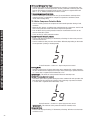
1) L o w Pr es s u r e Co n t r o l L o c k o u t
• The ICC will display a flashing “L” followed by a flashing 21 when a low pressure
control lockout occurs.
• The ICC addresses low pressure control faults differently depending on the mode
of unit operation (cooling or heating mode).
L
21
Active Protection – Code L21 – Open low pressure control
C o o l i n g Mo d e
• If the LPC opens three (3) times during the same command for cooling operation,
the ICC will lockout the compressor to keep it from continuing to operate and flash
a L” on the dual 7-segment LEDs followed by a “21”.
IMPORTA NT: This mode of active protection must be manually reset.
2) Hi g h Pr es s u r e Co n t r o l L o c k o u t
• If the HPC opens three (3) times during the same command for unit operation, the
ICC will lockout the compressor to keep it from continuing to operate and flash a
L” on the dual 7-segment LEDs followed by a “29”.
L
29
Active Protection – Code L29 – Open high pressure control
IMPORTA NT: This mode of active protection must be manually reset.
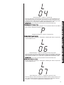
3) L o c k ed Ro t o r
• The ICC will display a flashing “L” followed by a flashing “04” when a locked rotor
condition occurs.
22
L
04
P
Compressor Protector – Code P – Protector Trip
5) Op en St ar t Ci r c u i t L o c k o u t
• The ICC will display a flashing “L” followed by a flashing “06” when an open start
circuit condition occurs.
L
06
Active Protection – Code L6 – Compressor open start circuit
If the ICC lockouts L6 and L7 detect current in the run circuit without current present in the start circuit, the ICC will lockout the compressor to keep it from continuing to operate and flash a “L” on the dual 7-segment LEDs followed by a “06”.
IMPORTA NT: This mode of active protection must be manually reset.
6) Op en Ru n Ci r c u i t L o c k o u t
• The ICC will display a flashing “L” followed by a flashing “07” when an open start
circuit condition occurs.
L
07
Active Protection – Code L7 – Compressor open run circuit
If the ICC detects current in the start circuit without current present in the run circuit, , the ICC will lockout the compressor to keep it from continuing to operate
and flash a “L” on the dual 7-segment LEDs followed by a “07”.
23
COMFORT CONTROL2 SYSTEM™ CONTROL WIRING
Active Protection – Code L4 – Locked rotor
If the ICC detects the compressor has run less than 15 seconds before the protector tripped for four (4) consecutive starts during the same command for unit
operation, the ICC will lockout the compressor to keep it from continuing to operate and flash a “L” on the dual 7-segment LEDs followed by a “04”.
IMPORTA NT: This mode of active protection must be manually reset.
4) Co m p r es s o r Pr o t ec t o r Tr i p
• If ICC detects a protector trip it will display a “P”. If protector doesn’t reset within 4
hours, the ICC display will change to “5”.
IMPORTA NT: This mode of active protection must be manually reset.
Ex i t i n g A c t i v e Co m p r es s o r Pr o t ec t i o n L o c k o u t
Three are three methods to reset the ICC after an active protection lockout:
1) Cycle the line voltage to the unit
2) Cycle 24VAC to the ICC (remove the R or C connection to the ICC)
3) Push the TEST button down with an insulated probe for one (1) second and
release
Note: The ICC will attempt to start the unit when the TEST button is pressed
and released
No t e: The preferred method of resetting the ICC is to push the TEST button down
for one (1) second.
13.X Test and Fault Recall Modes
COMFORT CONTROL2 SYSTEM™ CONTROL WIRING
Test Test
Modeand
(TestFault
Button
onFault
theModes
ICC)
12.6
Test
and
Recall Modes
13.X
Recall
• Enter TEST
mode
by
pressing
button
with an insulated probe for one (1) second
Tes t Button
Mo d e (Ton
es tthe
B uICC)
t t o the
n o nTEST
t h e IC
C)
Test Mode (Test
and
release.
• Enter
mode bythe
pressing
the TEST
button
with an insulated
forsecond
one
• Enter TEST
modeTEST
by pressing
TEST button
with
an insulated
probe forprobe
one (1)
• The TEST(1)
causes
ICC to do the following
second
andthe
release.
and release. mode
1) ResetsThe
theTEST
ICC
from
active
protection
mode
mode
causes
the
ICCfollowing
to dolockout
the following
• The TEST• mode
causes
theany
ICC
to do
the
2) Resets the 3-minute anti-short cycle timer
1) Resets the
ICC from
protection
lockout
mode
1) Resets
the any
ICC active
from active
protection
lockout
mode
3) Energizes the unit without a command for unit operation
2) Resets 2)
theBypasses
3-minutethe
anti-short
cycle
timer cycle timer
3-minute
anti-short
• If the 3-minute anti-short cycle timer or 30 second minimum run timer is active (a flashing
3) Energizes
the unit without
command
for unit operation
Energizes
unita without
command
for unit
operation
“c”, “C”, 3)
“h1”,
or “h2”the
is displayed
onathe
7-segment
LEDs)
and a command for unit
• If the 3-minute anti-short cycle timer or 30 second minimum run timer is active (a flashing
•
If
the
3-minute
anti-short
cycle
timer
or
30
second
minimum run timer is active (a
operation
is
present,
TEST
mode
causes:
“c”, “C”, “h1”,
or “h2”
is displayed
on the
7-segment
LEDs)
and a command
unit
“c”,momentarily
“C”,
“h”, or “H”
displayed
on the
dual 7-segment
LEDs)for
and
a com1) A “t”isflashing
topresent,
display
onisthe
7-segment
display
operation
TEST mode causes:
mand for unit operation is present, TEST mode causes:
1) A “t” to1)display
on the 7-segment
A “t” tomomentarily
display momentarily
on the dualdisplay
7-segment display
Lower case “t”
Lower case “t”
2) The compressor will start
Lower case “t”
2) Thewill
compressor
will start and the outdoor fan will operate
Thecompressor
display
change
2)3)The
will
start to a steady “c”, “C”, “h1”, or “h2” to show the current command
for
unit
operation.
3)
The
display
will
change
to “c”,
a steady
or “C”
to show
the current
command
for
3) The display will change to a steady
“C”,“c”
“h1”,
or “h2”
to show
the current
command
unit operation.
Note:
If
a
command
for
unit
operation
is
present
at
the
end
of
TEST
mode
will
cause
the unit
for unit operation.
to
continue
to
operate.
Note:
If a command for unit operation is present at the end of TEST mode will
Note: If a command
for
unit
operation operate.
is present at the end of TEST mode will cause the unit
cause for
the unit
unit operation
to continueistopresent,
• If no command
TEST mode causes
to continue to operate.
• If no“t”
command
for
unit
operation isLEDs
present, TEST mode causes
1) A steady
appears
on
the
7-segment
• If no command for unit operation is present, TEST mode causes
2) The compressor
will
start
1)“t”
A steady
“t”on
appears
on the dual
7-segment LEDs
1) A steady
appears
the 7-segment
LEDs
3) The compressor
will
turn
off
after
5-seconds.
2)
The
compressor
will
start
2) The compressor will start
Note: Entering
without
a command
for unit operation will cause the compressor
3) TheTEST
compressor
willafter
turn 5-seconds.
off
after 5-seconds.
3) The compressor
willmode
turn off
to
run
5-seconds.
Note: Entering
mode
without
command
for unit operation
will cause
compressor
Note:TEST
Entering
TEST
modea without
a command
for unit operation
willthe
cause
the
Fault
Recall
Mode (TEST
and5-seconds.
SW2 Buttons)
compressor
to run
to run
5-seconds.
• Enter FAULT RECALL mode by pressing the TEST and SW2 buttons at the same time
au l t R(TEST
ec al l Moand
d e (SW2
TESTButtons)
an d SW2 B u t t o n s )
Fault
Recall FMode
with insulatedRECALL
probes formode
one (1)
second
and
• Enter FAULT
by
pressing
therelease.
TEST
at the same
TESSW2
T andbuttons
SW2 buttons
• Enter FA UL T RECA L L mode by pressing
theand
at thetime
• When entering
and
exiting
FAULT
RECALL
mode
top and
same
time for
withone
insulated
probes
one
(1) the
second
and bottom
release.segments of the 7with insulated
probes
(1) second
andforrelease.
segment LEDs will illuminate.
• When entering and exiting FAULT RECALL mode the top and bottom segments of the 7• When entering and exiting FAULT RECALL mode the top and bottom segments
of the
dual
7-segment LEDs will illuminate.
segment LEDs
will
illuminate.
Fault
and
bottom
segments
on the
right
Fault Recall
RecallMode
Mode– –the
thetoptop
and
bottom
segments
illuminated
side are illuminated
Fault Recall Mode – the top and bottom segments illuminated
• When entering FA UL T RECA L L mode, the ICC will automatically scroll through
When entering
mode, theLEDs.
ICC will automatically scroll through stored
storedFAULT
faults onRECALL
the dual 7-segment
faults
on
the
7-segment
LEDs.
• When entering
RECALLone
mode,
automatically
scrollofthrough
• EachFAULT
fault is displayed
time the
withICC
the will
top right
hand segment
the dualstored
7• Each faultsegment
displayed
oneactivated
time with
the topfaults.
segment of the 7-segment display activated
display
between
faults on the is7-segment
LEDs.
between faults.
Each
fault isone
displayed
withthe
thetop
most
recent fault
first.
• Each fault• is
displayed
time with
segment
of thedisplayed
7-segment
display activated
• Each fault is displayed with the most recent fault displayed first.
between faults.
•
24
•
Each fault is displayed with the most recent fault displayed first.
8
to continue to operate.
If no command for unit operation is present, TEST mode causes
1) A steady “t” appears on the 7-segment LEDs
• A maximum of six individual faults can be stored
2) The compressor will start
• A maximum
of three
consecutive
identical faults are stored.
3) The compressor
will
turn off
after 5-seconds.
•
A
“0”
will
be
displayed
with
no
faults
are for
stored
Note: Entering TEST mode without a command
unit operation will cause the compressor
• The ICC will automatically exit the FA UL T RECA L L mode after displaying stored
to run 5-seconds.
faults (TEST and SW2 Buttons)
Fault Recall Mode
• Enter FAULT
Cl ear FRECALL
au l t Hi s t o rmode
y (TESby
T apressing
n d SW2the
B uTEST
t t o n s ) and SW2 buttons at the same time
with insulated probes for one (1) second and release.
• Clear FAULT HISTORY by pressing both TEST and SW2 button for five (5) sec• When entering
FAULT
mode the top and bottom segments of the 7onds and
with exiting
insulated
probesRECALL
and release.
segment•LEDs
will illuminate.
The top and bottom segments of the dual 7-segment LEDs flash to indicate the
•
history has been cleared.
Fault history
cleared
with
top
and bottom
LEDilluminated
Fault
Recall is
Mode
– the
topthe
and
bottom
segments
•
•
•
NOTE: The memory card for the system has specific shared data for this system.
The memory
cardRECALL
is attached
to thethe
control
a tether. The
tether
has anstored
When entering
FAULT
mode,
ICC box
willwith
automatically
scroll
through
identification tag that can be used to identify the memory card. For the system data
faults onfaults
the 7-segment
LEDs.
d1 through d8 reference the label on the memory card tether.
Each fault is displayed one time with the top segment of the 7-segment display activated
between faults.
Each fault is displayed with the most recent fault displayed first.
COMFORT CONTROL2 SYSTEM™ CONTROL WIRING
segments flash
8
25
cooling during an active anti-short cycle timer
or minimum run timer.
• Wait until unit timer has expired or press the
FLASHING
TEST button to reset timer.
12.7
COMFORT
CONTROL2 SYSTEM™
CONTROL
WIRING
C - Second Stage
Cooling
operation
Normal
AND
Unit has received a command for second
13.X
Codes
13.X
ICC
Diagnostic
Codes
13.X
ICC
Diagnostic
13.X ICC
ICC Diagnostic
Diagnostic
Codes
CONVENTIONAL THERMOSTAT WIRING
stage coolingCodes
13.X ICC Diagnostic Codes ICC DIAGNOSTIC CODES
- Anti-short
cycle timer
(3 minutes)
or
Descriptions
of
ICC
codes
are
below:
The unit has received a command for second
•below:
Descriptions
of
the
ICC
diagnostic
codes
are
provided
Descriptions
of
the
ICC
diagnostic
codes
are
provided
below:
Descriptions
ofCthe
the
ICCdiagnostic
diagnostic
codes
areprovided
provided
below:
ICC Diagnostic
Codes
run
timer
(30
seconds)
active
Minimum
stage
Descriptions of the ICC diagnostic codes are provided below:cooling during an active anti-short cycle
Descriptions of the ICC diagnostic codes are provided below:
7-Segment
7-Segment
7-Segment
7-Segment
LEDs
Display
LEDs
Display
7-Segment
LEDs
Display
Dual
7-Segment
LEDs
Display
FLASHING
Code
Diagnostic
Code
Diagnostic
Description
LEDs
Display
Diagnostic
Description
LEDs
Display
Code
Diagnostic
Description
Code
DiagnosticDescription
Description
h1
-–Standby
First
Stage Heat Pump
Code
0
–
0
Standby
Code
Diagnostic Description
00––Standby
Standby
Unit
has
received
aunit
command
for first stage
No
command
for
operation
0
Standby for
0No
––command
Standby
No
command
for
unit
operation
No
command
forunit
unitoperation
operation
heat
pump
No
No command
commandfor
forunit
unitoperation
operation
26
timer or minimum run timer.
• Wait
unit timer hasCause
expired Troubleshooting
or press the TEST
Status/Possible
Status/Possible
Cause
Status/Possible
Cause
Troubleshooting
Status/Possible
Cause–––––Troubleshooting
Troubleshooting
Status/Possible
Cause
Troubleshooting
button
to reset timer.
Information
Information
Status/Possible
Cause – Troubleshooting
Information
Information
Information
Normal
operation
Normal
operation
Normal
operation
Normal
Normaloperation
operation Information
Normal
operation
Normal operation
h1
Anti-short
cycle
timer (3 minutes) or
•Normal
The unit
has received a command for first stage
cccc-----First
Cooling
First
Stage
Cooling
Normal
operation
First
Stage
Cooling
Normal
operation
FirstStage
Stage
Cooling
Normaloperation
operation
Minimum
run
timer
(30
seconds)
active
heat
pump
during an active anti-short cycle
Unit
has
received
aaaacommand
has
received
command
for
first
stage
cUnit
First
Stage
Cooling
operation
Unit
has
received
command
for
first
stage
hasStage
received
commandfor
forfirst
firststage
stage Normal
cUnit
-- First
Cooling
Normal operation
timer
or
minimum
run timer.
cooling
cooling
Unit
has
forfor
first
stage
Unit
has received
receiveda acommand
command
first
stage
cooling
cooling
• Wait unit timer has expired or press the TEST
cooling
cooling
FLASHING
to reset
timer. aaacommand
cccc----Anti-short
cycle
timer
(3
minutes)
or
Anti-short
cycle
timer
(3
minutes)
or
••••button
The
has
Theunit
unit
hasreceived
received
commandfor
forfirst
firststage
stage
Anti-short
cycle
timer
minutes)
Anti-shortcycle
cycletimer
timer(3(3
(3minutes)
minutes)oror
or
unit
has
received
command
first
stage
The
unit
has
received
command
for
first
stage
cMinimum
-- Anti-short
• The
The
unit
has
received
a acommand
forfor
first
stage
Minimum
run
timer
(30
seconds)
active
run
timer
(30
seconds)
active
h2
Second
Stage
Heat
Pump
Normal
operation
cooling
during
an
active
anti-short
cycle
timer
cooling
during
an
active
anti-short
cycle
timer
cMinimum
- Anti-short
cycle
timer
(3 minutes)
or
Minimum
run
(30
seconds)
active
• cooling
The
unitduring
has received
a anti-short
command
for
first
stage
runtimer
timer(30
(30seconds)
seconds)
active
an
active
anti-short
cycle
timer
cooling
during
anactive
active
anti-short
cycle
timer
cooling
during
an
cycle
timer
Minimum
run
timer
Unit
has received
a command
for active
second
or
run
timer.
orminimum
minimum
runan
timer.
Minimum
run timer
(30 seconds)
active
cooling
during
active anti-short cycle timer
or
minimum
run
timer.
or
minimum
run
timer.
or
minimum
run
timer.
stage heat pump
••••• Wait
until
timer
has
expired
press
the
Wait
untilunit
unit
timer
hasexpired
expiredoror
orpress
press
the
Wait
until
unit
timer
has
the
or
minimum
run
timer.
Wait
until
unit
timer
has
expired
or
press
the
Wait
until
unit
timer
has
expired
or
press
the
FLASHING
FLASHING
TEST
button
to
defeat
short
cycle
delay.
TEST
button
to
reset
timer.
TEST
button
to
reset
timer.
FLASHING
FLASHING
• TEST
Wait
unit
has
expired or press the
button
tototimer
reset
TESTuntil
button
resettimer.
timer.
Anti-short
cycle
timer (3 minutes) or
•Normal
The
unit
has received
atimer.
command for second
C
------Second
Stage
Cooling
operation
C
Second
Stage
Cooling
Normal
operation
FLASHING h2
TEST
button
to
reset
CC
Second
Stage
Cooling
Normal
operation
C
Second
Stage
Cooling
Normal
operation
Second
Stage
Cooling
Normal operation
Minimum
run
timer
(30
seconds)
active
stage heat pump during an active anti-short
Unit
has
command
second
Unit
has
received
aacommand
command
for
second
C
- Second
StageaaaCooling
Normal operation
Unit
has
received
command
for
second
Unit
has
received
forfor
second
Unit
hasreceived
received
command
for
second
cycle timer or minimum run timer.
stage
cooling
stage
cooling
stage
cooling
Unit
has
received a command for second
stage
stagecooling
cooling
•
Wait unit timer has expired or press the TEST
stage
cooling
d1--Anti-short
–Anti-short
No
Shared
Datatimer
FLASHING
button
to reset
timer. command
ELECTRONICS
GROUP
TO
C
cycle
(3
minutes)
or
C
cycle
timer
(3
minutes)
or
•
The
unit
has
received
command
for
second
•
The
unit
has
received
command
for
second
CC
cycle
timer
(3
minutes)
Anti-short
cycle
timer
The
unit
has
received
forfor
second
C---–Anti-short
Anti-short
cycle
timer(3
(3minutes)
minutes)oror
or
••• The
second
d1
No Shared
Data
Theunit
unithas
hasreceived
receivedaaaaacommand
command
for
second
ELECTRONICS
GROUP
TO
d1d–Minimum
No
Shared
Data
Minimum
run
timer
(30
seconds)
active
Minimum
run
timer
(30
seconds)
active
Defrost
Active
Normal
operation
stage
cooling
during
an
active
anti-short
cycle
stage
cooling
during
an
active
anti-short
cycle
stage
cooling
during
active
cycle
ELECTRONICS
TO
Minimum
run
timer
seconds)
active
C
- Anti-short
cycle(30
timer
(3 minutes)
or
run
(30
seconds)
active
• stage
The unit
has received
aGROUP
command
for
second
Minimum
runtimer
timer
(30
seconds)
active
cooling
during
an
active
anti-short
cycle
DESCRIBE
stage
cooling
duringan
an
activeanti-short
anti-short
cycle
timer
or
minimum
run
timer.
The
unit
is
undergoing
a
defrost
cycle
timer
or
minimum
run
timer.
timer
or
minimum
run
timer.
DESCRIBE
Minimum run timer (30 seconds) active
stage
cooling
during
an
active
anti-short
cycle
timer
or
minimum
run
timer.
timerunit
or minimum
run
timer.
DESCRIBE
Wait
timer
has
expired
oror
press
the
TEST
••••• Wait
Wait
unit
timer
has
expired
press
the
TEST
Wait
unit
timer
has
expired
or
press
the
TEST
timer
or
minimum
run
timer.
unit
timer
expired
or
press
TEST
Wait
unit
timerhas
hasindoor
expired
ormover
pressthe
TEST
d3 – Airflow CFM Mismatch
Misapplied/wrong
–thereplace
button
to defeat
short
cycle air
delay.
FLASHING
FLASHING
button
toto
reset
timer.
button
reset
timer.
d3
– indoor
AirflowairCFM
Mismatch
FLASHING
FLASHING
•
Misapplied/wrong
indoor
air
mover
–
replace
Wait
unit
timer
has
expired
or
press
the
TEST
button
to
reset
timer.
button
to
reset
timer.
The
mover
(air
handler/furnace)
with
properly
sized
air
handler/furnace.
d3 –h1
Airflow
CFM
Mismatch
• The
Misapplied/wrong
indoor
air mover – replace
Test
Mode
ICC
isoperation
ininTEST
mode
First
Stage
Heat
Pump
Normal
operation
h1
First
Stage
Heat
Pump
Normal
t-The
Test
Mode
The
ICC
is
TEST
mode
FLASHING th1
indoor
air
mover
(air
handler/furnace)
with
properly
sized
air
handler/furnace.
button
to
reset
timer.
--First
Stage
Heat
Pump
Normal
operation
h1
First
Stage
Heat
Pump
Normal
operation
cannot
supply
the
required
airflow for
TheUnit
indoor
air
mover
handler/furnace)
with
properly
sized air handler/furnace.
has
received
a(air
command
for
first
stage
Unit
has
received
aacommand
command
for
first
stage
cannot
supply
the
required
airflow
forstage
h1
First
Stage
Heat
Pump
Normal
operation
Unit
has
received
a
for
first
Unit
has
received
command
for
first
stage
proper
system
operation
cannot
supply
the
required
airflow
for
heat
pump
heat
pump
proper
system
operation
Unit
has
received
a command for first stage • Motor protector open
heat
pump
heat
pump
P –system
Protector
Trip
proper
operation
P
–
Protector
Trip
• Motor
protector
open
heat
pump
A
command
for
compressor
operation is • Motor
Line
voltage
disconnected
P –h1
TripTrip
protector
open
PProtector
–--Protector
Motor
protector
open aacommand
Anti-short
cycle
timer
(3
minutes)
or
h1
Anti-short
cycle
timer
(3
minutes)
or
••••• The
The
unit
has
received
for
first
stage
The
unit
has
received
command
for
first
stage
A
command
for
compressor
operation
is
h1
Anti-short
cycle
timer
(3
minutes)
or
h1
Anti-short
cycle
timer
(3
minutes)
or
•
unit
has
received
aacommand
Line
voltage
disconnected
The
unit
has
received
commandfor
forfirst
firststage
stage
present
but
no
current
is
measured
to
the
A
command
for
compressor
operation
• heat
Line
voltage
disconnected
A command
for
compressor
operation
isis
•
Line
voltage
disconnected
Minimum
run
timer
(30
seconds)
active
Minimum
run
timer
(30
seconds)
active
pump
during
an
active
anti-short
cycle
heat
pump
during
an
active
anti-short
cycle
h1
Anti-short
cycle
timer
(3
minutes)
or
present
but
no
current
is
measured
to
the
Minimum
run
timer
(30
seconds)
active
• heat
The
unit
has
received
a command
for cycle
first
stage
Minimum
run
timer
(30
seconds)
active
pump
during
an
active
anti-short
heat
pump
during
an
active
anti-short
cycle
present
but
no
current
is
measured
to
the
compressor
present but no current is measured to the
10
timer
or
minimum
run
timer.
timer
or
minimum
run
timer.
Minimum
run
timer
(30
seconds) active
compressor
heat
pump
during
an
active
anti-short
cycle
compressor
timer
or
minimum
run
timer.
timer
or
minimum
run
timer.
01
–
Long
Run
Time
(Compressor)
• Low refrigerant charge
compressor
•
Wait
unit
timer
has
expired
or
press
the
TEST
•
Wait
unit
timer
has
expired
or
press
the
TEST
01
Long Run
Run Time
Time
(Compressor)run for
timer
or minimum
run
timer.
Low
refrigerant
charge
•••• Wait
unit
timer
has
expired
or
Wait
unit
timer
has
expired
orpress
pressthe
theTEST
TEST
The
has
continuously
–– compressor
Long
(Compressor)
Low
refrigerant
charge
Air
ducts
have
substantial
leakage
01 –01
Long
Run Time
(Compressor)
• Low
refrigerant
charge
FLASHING
FLASHING
button
toto
reset
timer.
button
reset
timer.
FLASHING
The
compressor
hascontinuously
continuously
run
for
FLASHING
Wait
unit
timer
has
expired
or
press
the
TEST
button
to
reset
timer.
•
Air
ducts
have
substantial
leakage
button
to
reset
timer.
The
compressor
has
run
for
•
Air
ducts
have
substantial
leakage
more
than
18
hours
in
the
cooling
mode.
• ducts
Dirtyoperation
indoor
air filter leakage
Theh2
compressor
has continuously
run for
have
substantial
----Second
Pump
Normal
h2
Second
Stage
Heat
Pump
Normal
operation
FLASHING
more
than18
18Stage
hoursHeat
the
coolingmode.
mode. • Air
more
than
hours
ininthe
cooling
• Dirty
indoor
air
filter
button
to
reset
timer.
h2
Second
Stage
Heat
Pump
Normal
operation
•
Dirty
indoor
air
filter
h2
Second
Stage
Heat
Pump
Normal
operation
•• Dirty
Dirty
outdoor
coil
more
than
18received
hours inaathe
coolingfor
mode.
• Dirty
indoor
air filter
Unit
command
coil
Unit
has
command
for
second
h2
-–has
Second
StageaaHeat
Pump
operation
Unit
has
received
command
for
second
Unit
hasreceived
received
command
forsecond
second
•Normal
Dirty outdoor
outdoor
coil
Reference
ICC
codes:
02
High
Pressure
Control
Open
outdoor coil
stage
heat
pump
stage
heat
pump
Unit
has
a Control
command
for second • Dirty
stage
heat
pump
02
–– ICC
High
Side
Fault
coil is
dirty (cooling mode)
stage
heatreceived
pump
Reference
ICC
codes:
02
High
Pressure
The
detects
the
HPC
is Open
open.
••• Outdoor
21
Reference
ICCfan
codes:
02 –Compressor
High
Pressure
Control
Open
Outdoor
is
not
running (cooling mode)
limit
has
opened
four
(4)
times
stage
heat
pump
The ICC detects the HPC is open.
• 21
L21unit
----Anti-short
(3
h2
Anti-short
cycle
timer
(3
minutes)
or
Theh2
ICC
detects
thecycle
HPCtimer
is open.
••••• The
has
received
aaaacommand
for
The
unit
has
received
command
for
second
Dirty
indoor
coil
or filter
(heating mode)
within
a call for
operation
h2
Anti-short
cycle
timer
(3
minutes)
or
h2
Anti-short
cycle
timer
(3minutes)
minutes)or
or • 21
The
unit
has
received
command
for
second
The
unit
has
received
command
forsecond
second
••• stage
L21
Indoor
blower
is
not
running
(heating
mode)
29
Minimum
run
timer
(30
seconds)
active
Minimum
run
timer
(30
seconds)
active
heat
pump
during
an
active
anti-short
stage
heat
pump
during
an
active
anti-short
h2 - Anti-short
cycle(30
timer
(3 minutes)
Minimum
run
seconds)
active
•
The
unit
has
received
a
command
for
second
Minimum
runtimer
timer
(30
seconds)
activeor • L21
stage
heat
pump
during
an
active
anti-short
stage
heat
pump
during
an
active
anti-short
•• Liquid
29
line restriction
L29 timer
or
minimum
run
timer.
cycle
timer
or
minimum
run
timer.
Minimum run timer (30 seconds) active • 29•• cycle
stage
heat
pump
during
an
active
anti-short
cycle
timer
or
minimum
run
timer.
cycle
timer
or
minimum
run
timer.
Excessive
refrigerant charge
L29
03 – Short Cycling
••••• Wait
unit
timer
has
expired
press
the
TEST
Wait
unit
timer
has
expired
or
press
the
TEST
Check
thermostat
wire
connections
(R,
C,
1, &
• L29
cycle
timer
or minimum
runor
Wait
unit
timer
has
expired
or
press
the
TEST
Wait
unit
timer
has
expired
ortimer.
press
the
TEST
03
– ICC
Shortdetects
Cycling
•
Check
thermostat
wire
connections
(R,
C,
1,
03
–
Short
Cycling
•
Check
thermostat
wire
connections
(R,
C,
1,
&&
FLASHING
FLASHING
The
the
run
time
for
the
past
button
to
reset
timer.
button
to
reset
timer.
2)
Short
Cycling
FLASHING
FLASHING 03 –The
• Check
thermostat
(R, C,
&
• button
Wait
unit
timerwire
hasconnections
expired or press
the1,TEST
totoreset
timer.
button
reset
timer.
ICC
detects
the
run
time
for
the
past
2)
The
ICC
detects
the
run
time
for
the
past
2)
four
(4)
compressor
cycles
is
less
than
three
----Defrost
Active
Normal
operation
d
Defrost
Active
Normal
operation
•• Check
Check
thermostat
location in zone
(too
close
to
FLASHING Thed
detects
the runcycles
time is
forless
thethan
pastthree
2)
button
to
reset timer.
dfour
Defrost
Active
operation
dICC
Defrost
Active
operation
(4)
thermostat
location
close
to to
four
(4)compressor
compressor
cycles
is less
than three Normal
•Normal
Check
thermostat
locationininzone
zone(too
(too
close
(3)
minutes
each.
unit
is
undergoing
a
defrost
cycle
The
unit
is
undergoing
a
defrost
cycle
discharge
grill)
fourThe
(4)
compressor
cycles
is
less
than
three
(3)
minutes
each.
discharge
grill)
d
Defrost
Active
Normal
operation
•
Check
thermostat
location
in
zone
(too
close
to
The
unit
aadefrost
Theminutes
unitisisundergoing
undergoing
defrostcycle
cycle
(3)
each.
grill)
L4 –unit
Locked
Rotor
• discharge
Bad run
capacitor
(3) minutes
each.
The
is undergoing
a defrost cycle
discharge
grill)
L4
–
Locked
Rotor
•
Bad
run
capacitor
L4
–
Locked
Rotor
•
Bad
run
capacitor
The
ICC detects
four (4) consecutive
• Low
line voltage
L4 –The
Locked
Rotor four
• Bad
run capacitor
ICC
detects
(4)
• Low
line
voltage
The
ICC
detects
fouroccurred
(4)consecutive
consecutive
t
Test
Mode
The
ICC
is
TEST
t
Test
Mode
The
ICC
TEST
mode
•
Low
line
voltage
protector
trips
have
and
the
t
Test
Mode
The
ICC
isis
inin
TEST
mode
•
Excessive
refrigerant
in
compressor
tICC
- Test
Mode
The
ICCvoltage
isin
in
TESTmode
mode
Theprotector
detects
four
(4)
consecutive
line
trips
have
occurred
andand
thethe
run time • Low
•
Excessive
refrigerant
inin
compressor
protector
trips
have
occurred
•
Excessive
refrigerant
compressor
average
run
time
for
each
trip
is
less
than
15
t
Test
Mode
The
ICC
is
in
TEST
mode
before trips
each have
trip isoccurred
less thanand
15 seconds
•• Seized
Seizedbearings
bearingsinincompressor
protector
the
refrigerant
incompressor
compressor
average
run time for each trip is less than 15• Excessive
seconds
• Seized bearings in compressor
average
run time for each trip is less than 15 • Seized
bearings
in
compressor
seconds
05 – Open Circuit (Compressor will not
• Check for damaged, miswired, or wrong run
seconds
05
– Open Circuit (Compressor will not
•
Check
for damaged, miswired, or wrong run
Run)
capacitor
05 – Open Circuit (Compressor will not
• Check
for damaged, miswired, or wrong run
Run)
capacitor
•
The
ICC
has
received
a
command
for
• Check for broken wires, loose connectors, or
Run)
capacitor
• The ICC
has received
a command
for in • Check
for compressor
broken wires, loose connectors, or10
10
but anocommand
current
isfor
present
miswired
• The unit
ICCoperation
has received
10
• Check
for broken
wires, loose connectors, or 10
unit
operation
butcircuits.
no current is present in • miswired
compressor
the
start
and
run
Checkcompressor
compressor windings for continuity 10
unit operation but no current is present in
miswired
L
07
(3)
(3) minutes
minutes each.
each.
01
–––Long
Run
Time
01
Long
Run
Time(Compressor)
(Compressor)
Locked
L4
L4 compressor
– Locked Rotor
Rotor
has
continuously
run
The
The
compressor
has
continuously
runfor
for
The
ICC
detects
four
(4)
consecutive
The than
ICC 18
detects
four
(4) cooling
consecutive
more
hours
in
the
mode.
thantrips
18 hours
in
the cooling
mode.
more
protector
have
occurred
and
the
protector trips have occurred and the
Dual 7-Segment average run time for each trip is less than 15
run
time for each
trip is less than 15
LEDs Display 02average
Diagnostic
Description
––High
seconds
02
HighPressure
PressureControl
ControlOpen
Open
seconds
Code
The
ICC
detects
the
HPC
is
open.
The
ICC
detects
the
HPC
is
open.
Open
Circuit
(Compressor
will
05
05–––Open
Opencircuit
Circuit(Compressor
(Compressor
will not
not
05
will not
Run)
Run)
Run)
The
ICC
has
received
aa command
TheICC
ICChas
hasreceived
received
command
for
••• The
a command
for for
unit
operation
but
current
present
unit
is is
present
in in
unitoperation
operationbut
butnono
nocurrent
current
is
present
in
start
and
circuits
start
and
run
circuits.
03
–the
the
startCycling
andrun
run
circuits.
03the
–Short
Short
Cycling
•• The
ICC
will
attempt
totorestart
the
unit
The
ICC
will
attempt
restart
the
unit
The
ICC
detects
the
for
the
past
The
ICC
detects
therun
runtime
time
for(4)
the
past
• every
The
ICC
willminutes
attempt
tofour
restart
the
unit
five
(5)
for
every
five
(5)
minutes
for
four
(4)
four
(4)
compressor
cycles
is
less
than
three
four
(4)
compressor
cycles
is
less
than
three
every five
(5) that,
minutes
for four
(4)
attempts.
After
the
ICC
will
attempt
uing to operate and flash a “L” on the 7-segment LEDs followed by a “21”. Once
attempts.
After
that,
the
ICC
will
attempt
(3)
minutes
each.
a
restart
every
twenty
(20)
minutes
for
up
(3)attempts.
minutes
each.
After that, the ICC will attempt
tdoor ambient rises above 5°F the ICC will clear active
protection automatically.
to
four
(4)
hours.
a
restart
every
twenty
(20)
minutes
for
L4
Rotor
restart
twenty (20) minutes for up
up
L4–a–Locked
Lockedevery
Rotor
•
The
ICC
has
had
a protector
trip for longer
ORTANT: This mode of active protection will automatically
deactivate
once
the consecutive
to
four
(4)
hours.
The
ICC
detects
four
(4)
to
four
(4)
hours.
The
ICC
detects
four
(4)
consecutive
than
4 hours.
or temperature rises above 5°F. Wait until the outdoor
ambient
temperature
rises Start Circuit
06
Open
protector
trips
occurred
06 –– Compressor
Compressor
Open
Startand
Circuit
protector
tripshave
have
occurred
andthe
the
5°F before performing further diagnostics.
06
Compressor
Open
Start
Circuit
The
detects
current
in
the
average
run
time
trip
isisRun
less
than
The– ICC
ICC
detects
current
in
the
Run
circuit
average
run
timefor
foreach
each
trip
lesscircuit
than15
15
The
ICCindetects
current
in the
Runcompressor
circuit
ssure Control Lockout
but
circuit
of
seconds
but not
not
in the
the Start
Start
circuit
of the
the compressor
seconds
but for
notunit
inoperation,
the Startthecircuit
HPC opens three (3) times during the same command
ICC of the compressor
––Open
will
05operate
Open
Circuit
(Compressor
willnot
not
ckout the compressor to keep it from continuing05
to
andCircuit
flash
a L”(Compressor
on
the 7Run)
nt LEDs followed by a “29”.
Run)
Compressor
Open
Run
Circuit
•06
The
ICC
aRun
•07
The
ICChas
hasreceived
received
acommand
command
for
07
Compressor
OpenStart
Circuit for
–––Compressor
Open
Circuit
The
ICC
detects
current
in
the
Start
circuit
unit
operation
but
no
current
is
present
inin
unit
operation
but noincurrent
is present
The
ICC
detects
thethe
Run
The
ICC
detectscurrent
current
in
Start
circuit
but
not
in
the
Run
circuit
of
the
compressor
circuit
but
not
in
the
Start
circuit
of
the
the
start
and
run
circuits.
andRun
runcircuit
circuits.
butthe
notstart
in the
of the compressor
five
times,
4 to
retries
in the
one
•compressor
• The
TheICC
ICCwill
willattempt
attempt
torestart
restart
theunit
unit
compressor
call
every
five
(5)
minutes
for
four
(4)
every five (5) minutes for four (4)
attempts.
After
the
attempts.
Afterthat,
that,
theICC
ICCwill
willattempt
attempt
09
–– Low
Volts
09
Low Secondary
Secondary
Volts
a
restart
every
twenty
(20)
minutes
for
a restart
every
twentyat
minutes
forup
up
The
secondary
voltage
R
C
The
secondary
voltage
at(20)
R and
and
C is
is below
below
to
four
(4)
hours.
07
– Compressor
Open Run Circuit
to
four (4) hours.
18VAC
18VAC
Active Protection – Code L29 – Open high pressure control
The
ICC
detects current
inStart
theCircuit
Start
circuit
06
Open
06––Compressor
Compressor
OpenStart
Circuit
but
not
indetects
the Run
circuitinin
ofthe
theRun
compressor
ICC
current
circuit
ORTANT: This mode of active protection must The
be
manually
deactivated.
The
ICC
detects
current
the
Run
circuit
but
butnot
notininthe
theStart
Startcircuit
circuitofofthe
thecompressor
compressor
discharge
grill)
discharge grill)
• •• Low
refrigerant
Low
refrigerantcharge
charge
• Bad
Bad run
run capacitor
capacitor
• •• Air
ducts
have
substantial
leakage
Air
ducts
have
substantial
leakage
• Low
Low line
line voltage
voltage
indoor
air
filter
• •• Dirty
Dirty
indoor
air
filter
Excessive refrigerant
refrigerant in
in compressor
compressor
• Excessive
• •• Dirty
outdoor
coil
Dirty
outdoor
coil
Status/Possible
Cause
– Troubleshooting
Seized
bearings
in
compressor
• Seized bearings in compressor
Reference
Information
ReferenceICC
ICCcodes:
codes:
• ••21
21
Check
for
damaged,
miswired,
or
run
Checkfor
fordamaged,
damaged,
miswired,
or wrong
wrong
Check
miswired,
or wrong
runrun
• •• L21
capacitor
L21
capacitor
capacitor
• ••• 29
Check
for
broken
wires,
loose
connectors,
29
Checkfor
forbroken
brokenwires,
wires,loose
loose
connectors,
or
Check
connectors,
or or
• • L29
miswired
compressor
L29
miswiredcompressor
compressor
miswired
Check
compressor
windings
continuity
• ••• Check
wire
connections
(R,
Check
compressor
windings
forfor
continuity
thermostat
wire
connections
(R,C,C,1,1,&&
Checkthermostat
compressor
windings
for
continuity
for
open
compressor
internal
protector
••• 2)Check
Check
for
open
compressor
internal
2)
Check for open compressor internal protector
protector
•
No
retries,
contactor
remains
(infinite
• • Check
thermostat
location
ininclosed
zone
Check
thermostat
location
zone(too
(tooclose
closetoto
retries)
discharge
dischargegrill)
grill)
• • Bad
Badrun
runcapacitor
capacitor
• • Low
Lowline
linevoltage
voltage
Check
for
damaged,
miswired,
or
Check
for
damaged, in
miswired,
or wrong
wrong run
run
• •••Excessive
refrigerant
Excessive
refrigerant
incompressor
compressor
• Check
for
damaged,
miswired,
or
wrong
run
capacitor
capacitor
• • Seized
bearings
in
compressor
Seized bearings in compressor
capacitor
••• Check
Check
for
broken
wires,
loose
connectors,
Checkfor
forbroken
brokenwires,
wires,loose
looseconnectors,
connectors,
or
or or
miswired
compressor
• • Check
for
damaged,
miswired
compressor
miswired
Check
forcompressor
damaged,miswired,
miswired,ororwrong
wrongrun
run
Check
forfor
continuity
•••capacitor
Check
compressor
windings
continuity
capacitor
Checkcompressor
compressorwindings
windings
for
continuity
Check
for
damaged,
miswired,
or
• ••• Check
for
broken
wires,
loose
connectors,
oror
broken
wires,
looseorconnectors,
Checkfor
fordamaged,
damaged,
miswired,
or wrong
wrong run
run
Check
miswired,
wrong
capacitor
miswired
compressor
run
capacitor
miswired
compressor
capacitor
Check
for
loose
connectors,
for
broken
wires,
loose
connectors,
• ••• Check
windings
for
continuity
Check
compressor
windings
for
continuity or
Checkcompressor
forbroken
brokenwires,
wires,
loose
connectors,
or
or
miswired
compressor
miswired
compressor
• • Check
for
open
compressor
internal
protector
miswired
compressor
Check
for
open
compressor
internal
protector
• Check compressor windings for continuity
•• Check
Check compressor
compressor windings
windings for
for continuity
continuity
•• Control
transformer
overloaded
Control transformer overloaded
•• Low
Low line
line voltage
voltage
• Check for damaged, miswired, or wrong run
capacitor
• • Check
Checkfor
fordamaged,
damaged,miswired,
miswired,ororwrong
wrongrun
run
• capacitor
Check for broken wires, loose connectors, or
capacitor
miswired compressor
• •• Check
Checkfor
forbroken
brokenwires,
wires,loose
loose
connectors,oror
Check
compressor
windings
forconnectors,
continuity
otor
miswired
compressor
miswired
compressor
CC will display a flashing “L” followed by a flashing “4” when a locked rotor
ion occurs.
• • Check
Checkcompressor
compressorwindings
windingsfor
forcontinuity
continuity 11
07
–
Compressor
Open
Run
Circuit
• • Check
07 – Compressor Open Run Circuit
Checkfor
fordamaged,
damaged,miswired,
miswired,ororwrong
wrongrun
run
07 –ICC
Compressor
Open Run
Circuit
• Check for damaged, miswired, or wrong
The
detects
current
ininthe
Start
circuit
capacitor
The
ICC
detects
current
the
Start
circuit
capacitor
The ICC detects current in the Start
run capacitor
but
ininthe
circuit
butnot
notbut
theRun
Run
circuit
ofthe
thecompressor
compressor
• •• Check
wires,
loose
connectors,
Checkfor
forbroken
brokenwires,
wires,loose
looseconnectors,
connectors,oror
circuit
not
in the
Run of
circuit
of
the
Check
for
broken
compressor four (4) times in one
or
miswired
compressor
miswired
compressor
miswired
compressor
compressor call (4 retries)
Check
compressor
for
continuity
• •• Check
windings
for
continuity
Active Protection – Code L4 – Locked rotor
Checkcompressor
compressorwindings
windings
for
continuity
09
–
Low
Secondary
Volts
•
Control
transformer
overloaded
09 –– Low
Low Secondary
SecondaryVolts
Volts
09
•• Control
Control transformer
transformeroverloaded
overloaded
ICC detects the compressor has run less than 15 seconds for four (4) consecutive
voltage
and
below
The
secondary
voltage
atatat
RRR
and
CCC
isisis
below
Low
line
voltage
Thesecondary
secondary
voltage
and
below • •• Low
Lowline
linevoltage
voltage
during the same command for unit operation, theThe
ICC
will
lockout the
compressor
18VAC
18VAC
21
Low Pressure
Control
p it from continuing to operate and flash a “L” on
the–7-segment
LEDs followed
by Open
• Unit has low refrigerant charge
18VAC
21 –ICC
Lowdetects
Pressure
Open
• Unit has low refrigerant charge
The
theControl
LPC is open.
• Indoor coil is frozen (cooling mode)
The
ICC
detects
the
LPC
is
open.
• Indoor
coil
frozen (cooling
mode)
Note:
The
low
pressure
control
is
ignored
21manually
– Lowdeactivated.
Pressure Control Open
Unit has
lowiscoil
refrigerant
ORTANT: This mode of active protection must be
• • Dirty
indoor
or filtercharge
(cooling mode)
Note:
The
low
pressure
•
Dirty
indoor
coil
or
filter
(cooling
mode)
Thethe
ICC
detects
the LPCofcontrol
iscompressor
open.is ignored
•
Indoor
coil
is
frozen
(cooling
mode)
for
first
90 seconds
• Indoor blower is not running (cooling
mode)
rt Circuit Lockout
for
theThe
firstlow
90 pressure
secondscontrol
of compressor
Note:
is ignored
• Indoor
Dirty indoor
coilis or
filter
(cooling
mode)mode)
•
blower
not
running
(cooling
operation
•
Outdoor
coil
is
frozen
(heating
mode)
for the first 90 seconds of compressor
• Indoor blower is not running (cooling mode) 11
operation
• Outdoor
coilisis frozen
frozen(heating
(heatingmode)
mode)
11
operation
Outdoor fan
coil
• • Outdoor
is not running
(heating mode)
•• Outdoor
fan
is not
running
(heating
mode)
Expansion
valve
is
not
operating
correctly
• Expansion valve is not operating correctly
6
• Expansion
valve is
correctly
L21
The
has locked
outnot
theoperating
compressor
due to
Low Pressure
Pressure
L21 ––Active
Active Protection
Protection Low
(seeICC
21 above)
L21
–
Active
Protection
The
ICC
has
locked
out
the
compressor
due to
Low
Pressure
Control Trip
Trip
LPC(3)
hasconsecutive
opened 3 times
the same
Control
three
LPCintrips
on thecooling
same
Control Trip
three
(3)
consecutive
LPC
trips
on
the
same
operation,for
theunit
ICCoperation
has locked out the compressor
command
LPC has opened 3 times in the same cooling
command
forICC
unit alternately
operation flashes L and 21
to protect it.
operation, the ICC has locked out the compressor to protect it. ICC alternately flashes L and
21
L
06
L
07
FLASHING
FLASHING
27
or No
No Line
Line Voltage
Voltage
27––Low
Low Line
Line Voltage
Voltage or
27 – Low Line Voltage or No Line Voltage
Fault
Fault
Fault
28 – High Line Voltage Fault
28 – High Line Voltage Fault
• • Check
voltage to
to the
the disconnect
disconnect
Check incoming
incoming line
line voltage
• and
Check
incoming
line
voltage
to
the
disconnect
unit
and unit
and
unit
Check wiring
wiring connections
connections
• • Check
• Check wiring connections
• Check line voltage
• Check line voltage
29 – High Pressure Control Open
• Outdoor coil is dirty (cooling mode)
27
FLASHING
FLASHING
• Check incoming line voltage to the disconnect
27 – Low Line Voltage or No Line Voltage
21 – Low Pressure Control Open
• Unit has low refrigerant charge
unit
Fault
27 – Low Line Voltage or No Line Voltage
• and
Check
incoming line voltage to the disconnect
The ICC detects the LPC is open.
• wiring
Indoor connections
coil is frozen (cooling mode)
•
Check
Fault
and
unit
Dual
7-Segment
FLASHING
Status/Possible
Cause
Troubleshooting
The
low
pressure
control
is
ignored
Note:
FLASHING
•
Dirty
indoor
coil or– filter
(cooling mode)
LEDs Display
Diagnostic Description
• Check
Check incoming
wiring connections
Information
27 –– Low
Low
Line
Voltage
or
No Line
Line
Voltage
line
voltage
to
the
disconnect
Check
incoming
line
voltage
to
the
disconnect
the
90 seconds
of compressor
for Line
28
High
Linefirst
Voltage
Fault
27
Voltage
or
No
Voltage
Code
line
voltage
••• Check
line voltage
to the disconnect
• incoming
Indoor blower
is not running
(cooling mode)
Fault
and
unit
Fault operation
unit
and
Fault
unit
• line
Outdoor
coil is frozen (heating mode)
28
Fault
•• • and
Check
voltage
28––High
High Line
Line Voltage
Voltage Fault
Check
line
voltage
Check wiring
wiring connections
connections
Check
•• Check
• wiring
Outdoorconnections
fan is not running (heating mode)
•
Expansion
valve is not operating correctly
28Pressure
High Line
Line
Voltage
Fault
•• Outdoor
Check
line
voltage
Check
line
voltage
21 – Low
Control
Open
• Unit has
low refrigerant
charge
Pressure
Control
Open
29
28
–– High
Voltage
Fault
coil
is
dirty
(cooling
mode)
line
voltage
L21 – Active
Protection
Low Pressure • Check
The
ICC
has
locked
out the
compressor due to
The ICCThe
detects
the
LPC
is
open.
ICC
detects
the
HPC
is
open
•
Indoor
coil
is
frozen
(cooling
mode)
•
Outdoor
fan
is
not
running
(cooling
mode)
–
High
Pressure
Control
Open
Outdoor
coil
is
dirty
(cooling
mode)
29
•
29 – High
Pressure
• Outdoor
dirty (cooling
Control
Trip Control Open
threecoil
(3) is
consecutive
LPCmode)
trips on
the same
Outdoor
fan
is
not
running
(cooling
mode)
•
Note: The
low
pressure
control
is
ignored
The
ICC
detects
the
HPC
is
open
•
Dirty
indoor
coil
or
filter
(cooling
mode)
•
Dirty
indoor
coil
or
filter
(heating
mode)
The ICC detects the HPC is open
• • Outdoor
fan
is
not
running
(cooling
mode)
command
fororunit
operation
Dirty
indoor coil
filter
(heating mode)
for the first 90 seconds of compressor
• Indoor
is
not running
(cooling
mode)
•• •blower
Indoor
blower
isdirty
not
running
(heating
mode)
Dirty
indoor
coil
or
filter
(heating
mode)
29
–
High
Pressure
Control
Open
Indoor
blower
is
not
running
(heating
mode)
Outdoor
coil
is
(cooling
mode)
29
–
High
Pressure
Control
Open
Outdoor
coil is
is(heating
dirty (cooling
(cooling
mode)
operation
29 – High Pressure Control Open
••• • Outdoor
coil
dirty
mode)
•
Outdoor
coil
is
frozen
mode)
Liquid
line
restriction
Liquid
line
restriction
Indoor blower
running
(heating
mode)
The
ICC
detects
the
HPC
is
open
Outdoor
fan
is
not
running
(cooling
mode)
The ICC
ICC detects
detects the
the HPC
HPC is
is open
open
Outdoor
fan
is is
notnot
running
(cooling
mode)
The
•••• • Outdoor
fan
is
not
running
(cooling
mode)
Excessive
refrigerant
charge
• Outdoor
fan isindoor
not
running
(heating
mode)mode)
Excessive
refrigerant
charge
Liquid
line
restriction
••• Dirty
Dirty
coil
or
filter
(heating
Dirty
indoor
coil
or filter
filter correctly
(heating mode)
mode)
indoor
coil
or
(heating
valve
islocked
not
operating
L29
High Pressure
Pressure• Expansion
The
ICC
has
outrunning
the
compressor
due
to
L29 ––Active
Active Protection
Protection High
29
above)
• (see
Excessive
refrigerant
charge
Indoor
blower
is
not
(heating
mode)
•
Indoor
blower
is
not
running
(heating
mode)
FLASHING
•three
Indoor
blower
is times
not
running
(heating
mode)
Control
Trip
(3)
consecutive
HPC
trips
on
the
same
L21 – Active
Protection
Low
Pressure
The
ICC
has
locked
out
the
compressor
due
to
Control
Trip
LPC
has
opened
3
in
the
same
cooling
L29 – Active Protection High Pressure
ICC has
locked
out the compressor due to
•The
Liquid
line
restriction
– Low Line Voltage or No Line
Voltage
• Check
incoming
voltage
to the disconnect
operation,
theLPC
ICC
has locked
out
the compressor
Liquid
line
restriction
for
unit
operation
Control Control
Trip 27
three
(3)•command
consecutive
trips
on line
the
same
Trip
three
(3)
consecutive
HPC
trips
on the
same
Excessive
refrigerant
charge
LPC has
opened 3 times in the same cooling
tofor
protect
it. refrigerant
ICC
flashes
L and
29
Excessive
refrigerant
charge
Fault
unit alternately
•••command
Excessive
charge
command
unitand
operation
forlocked
unit operation
operation,
theProtection
ICC has locked
out
the comL29
–
Active
High
Pressure
The
ICC
has
out
the
compressor
due
to
• has
Check
wiring
L29
– Active
Protection
High Pressure
ICC
locked
out connections
the compressor due to
pressor
to
protect
it. ICC alternately
flashes L The
Control
Trip
three
(3)
consecutive
HPC
trips
on
the
same
Control
Trip
three (3)
(3) consecutive
consecutive HPC
HPC trips
trips on
on the
the same
same
Control
three
and 29 Trip
command
for
unit
operation
28 – High Line Voltage Fault
• Check
voltage
command
for unit
unitline
operation
command
for
operation
FLASHING
FLASHING
27 – Low
Voltage
• Check• •incoming
line
voltage
the is
disconnect
30
––Fuse
Open
The
fuse
on the
thetoICC
ICC
is open.
open.
30Line
Fuse
Openor No Line Voltage
The3-amp
3-amp
fuse
on
FLASHING
29detects
– Highthe
Pressure
Control
Open
•
Outdoor
coil
is
dirty
(cooling
mode)oror
Fault The
and
unit
ICC
the
on-board
fuse
is
open
The
ICC
detects
on-board
fuse
is
open
•
Low
voltage
wiring
at
R
and
C
is
•
Low
voltage
wiring
at
R
and
C
is damaged
damaged
30 – Fuse Open
• The 3-amp fuse on the ICC is open.
The ICC detects the HPC is open• Check wiring
• connections
Outdoor fan is not running (cooling mode)
miswired.
The
on-board fuse is open
d1 –ICC
No detects
Shared the
Data
• miswired.
Low
voltage wiring at R and
C is damaged
or
FLASHING
ELECTRONICS
GROUP
FLASHING
FLASHING
•
Dirty indoor coil or filter
(heatingTO
mode)
miswired.
30
Fuse
Open
The
3-amp
fuse
onindoor
theisICC
ICC
is
open.– (heating mode)
30
Fuse
Open
28 – High
Voltage
FaultTemperature Fault• Check••• •line
The
3-amp
fuse
on
the
ICC
is
open.
80Line
Low
Air Flow
Misapplied/wrong
air is
mover
voltage
83
Condenser
Coil
30
––––Fuse
Open
Replace
thefuse
sensor
The
on
the
open.
•3-amp
Indoor
blower
not
running
DESCRIBE
The
ICC
detects
the
on-board
fuse
is
open
The
ICC
detects
that
the
indoor
unit
is
replace
with
properly
sized
unit.
•
Low
voltage
wiring
at
R
and
C
is damaged
damaged or
or
The
ICC
detects
the
on-board
fuse
is
open
sensor
detects
abnormally
or
The
ICC
detects
theanon-board
fuselow
is open
• Low
wiring
at R and C is
•voltage
Liquid
line restriction
83
Condenser
Temperature
Replace
the sensor
not– providing
theCoil
minimum
airflowFault
miswired.
miswired.
high
coil
temperature
• Excessive refrigerant
The
detects
abnormally low or
d3 –sensor
Airflow
CFManMismatch
• miswired.
Misapplied/wrong
indoor aircharge
mover – replace
requirements.
L29
–
Active
Protection
High
Pressure
The
ICC
has
locked
out
the
compressor due to
high
coil
temperature
The
indoor
air
mover
(air
handler/furnace)
with
properly
sized
air
handler/furnace.
83
–
Condenser
Coil
Temperature
Fault
83Pressure
Condenser
Coil
Temperature
Fault
Replace
theplacement
sensor
Replace
the
sensor
83
Condenser
CoilOpen
Temperature
Fault
29 – High
Control
84
––Condenser
Outdoor
Ambient
Temperature
Fault
• Outdoor
coilthree
isunit
dirty
(cooling
mode)
83
Coil
Temperature
Fault
Check
– IfHPC
the outdoor
unit
in
•• • Replace
the
Control
Trip
(3)sensor
consecutive
trips
the is
same
cannot
supply
the
required
airflow
for
The
sensor
detects
an
abnormally
low
or
The
sensor
detects
an
abnormally
low
or
•
Check
sensor
is
installed
correctly
on on
control
The
sensor
detects
anopen
abnormally low
low or
or• Outdoorafan
The ICCThe
detects
thedetects
HPC
isan
is
not
running
(cooling
mode)
sensor
abnormally
high
temperature
area,
wait
until
the
ambient
84
–
Outdoor
Ambient
Temperature
Fault
• Check
unit placement
If the outdoor unit is in
command
for unit –operation
proper
operation
high
coilsystem
temperature
high
coil
temperature
high
outdoor
ambient
temperature
coil
temperature
or filter
mode)
temperature
drops(heating
and
sensor
reading.
The
detects
highcoil
temperature
area,check
wait
until the
ambient
P – sensor
Protector
Tripan abnormally low or• Dirty indoor
• aMotor
protector open
•
Indoor
blower
is
not
running
(heating
mode)
•
Replace
the
sensor.
high
outdoor
ambient
temperature
temperature
drops
and
check
sensor
reading.
A
command
for
compressor
operation
is
84
–
Outdoor
Ambient
Temperature
Fault
84
–
Outdoor
Ambient
Temperature
Fault
•
Check
unit
placement
–
If
the
outdoor
unit
•
Check
unit
placement
–
If
the
outdoor
unit
is
in
•
Line
voltage
disconnected
84 –– Outdoor
Outdoor Ambient
Ambient Temperature
Temperature Fault
Fault
Check
unit placement
placement –– If
If the
the outdoor
outdoor unit
unitisis
isinin
in
84
••• line
Check
unit
• Liquid
restriction
90
– sensor
Communication
Fault
Replace
the ICC.
The
sensor
detects
an
abnormally
low
or
a
high
temperature
area,
wait
until
the
ambient
sensor.
present
but
no
current
is
measured
to
the
The
detects
an
abnormally
low
or
a
high
temperature
area,
wait
until
the
ambient
The
sensor
detects
an
abnormally
low
or
a
high
temperature
area,
wait
until
the
ambient
The
sensor
detects
aninternal
abnormally
or• Excessive
atemperature
high
temperature
area,
waitsensor
until reading.
the ambient
The
detects
and
fault low
condition
high
outdoor
ambient
temperature
drops
and
check
refrigerant
charge
90
– ICC
Communication
Fault
compressor
• temperature
Replace
the ICC.
high
outdoor
ambient
temperature
drops
and
check
sensor
reading.
high
outdoor
ambientControl
temperature
temperature
drops
and check
check
sensor reading.
reading.
high
outdoor
ambient
temperature
temperature
drops
and
sensor
•
Replace
the
sensor.
21
–
Low
Pressure
Open
•
Unit
has
low
refrigerant
charge
L29 – Active
Protection
High
Pressure
The ICC••has
locked
outsensor.
the compressor
due to
The
detects
and
internal
fault condition
01 –ICC
Long
Run Time
(Compressor)
Low
refrigerant
charge correctly
Replace
the
•
Replace
the
sensor.
•
Check
sensor
is
installed
on
the
sensor.
Thecompressor
ICC detectshas
thecontinuously
LPC is open.run for
FLASHING
•Replace
Indoor
coil
is frozen
mode)control
Control 90
Trip
three (3)••consecutive
HPC
trips on(cooling
theleakage
same
The
Air
ducts
have
substantial
–
Communication
Fault
•
Replace
the
ICC.
90
–
Communication
Fault
Replace
the3-amp
ICC.
Note:
The
low
pressure
is mode.
ignored
90
––Communication
Fault
30
– 18
Fuse
Open
93
Internal
Control
Fault
Check
control
for proper
•• ••for
Replace
the
ICC.
• The
fuse
onsystem
the
ICC ismode)
open.
Dirty
indoor
coil
or filter
(cooling
command
unit
operation
more
than
hours
in
thecontrol
cooling
• Dirty
indoor
air
filter
The
ICC
detects
and
internal
fault condition
condition
The
control
is90
not
functioning
forICC
the
first
seconds
of on-board
compressor
The
detects
and
internal
fault
The
ICC
detects
the
fuse is open• operation.
• Low
voltage
wiring
at R(cooling
and C ismode)
damaged or
Indoor
blower
is not
running
•• Replace
Dirty
outdoor
properly.
controlcoil
operation
miswired.
•
Outdoor
coil
is
frozen
(heating
mode)
02 – High Pressure Control Open
Reference ICC codes:
• 21
Outdoormemory
fan is not
running
(heating
mode)
The
detects
the
HPC
is
open.
d1––ICC
No
Shared
Data
d1
No
Shared
Data
card
with correct
system
83 – Condenser Coil Temperature Fault •• Replace
• Replace
the
sensor
ELECTRONICS
GROUP
TO12
•
Expansion
valve
is
not
operating
correctly
L21
The sensor detects an abnormally low or • information.
DESCRIBE
L21 – Active Protection Low Pressure
•The
29ICC has locked out the compressor due to12
FLASHING
high coil temperature
Control Trip
three (3) consecutive LPC trips on the same
• L29
30 – Fuse Open
• The 3-amp
fuse on
ICC
is open.
command
forthe
unit
operation
d3
–
Airflow
CFM
Mismatch
•
Misapplied/wrong
indoor
airair
mover
– outdoor
d3
–
Airflow
CFM
Mismatch
•
Misapplied/wrong
– replace
12
84the
– Outdoor
Temperature
Fault
•
Check
unit
placement
–mover
If the
unit
The ICC 03
detects
on-boardAmbient
fuse is open
– Short
Cycling
12
•
Check
thermostat
wire
C, 1,12
& is in
• Low voltage
wiring
atproperly
R andindoor
C
isconnections
damaged
or(R,
The
indoor
air
mover
(air
replace
with
sized
air
d1
–
No
Shared
Data
The
indoor
air
mover
(air
handler/furnace)
with
properly
sized
air
handler/furnace.
The
sensor
detects
an
abnormally
low
or
a
high
temperature
area,
wait
until
the
ambient
ELECTRONICS
GROUP
TO
The
ICC
detects
the
run
time
for
the
past
2)
handler/furnace)
cannot
supply
the for miswired.handler/furnace.
cannot
supply
the
required
airflow
high
outdoor
ambient
drops and
sensor
reading.
four
(4)
compressor
cycles
istemperature
less than three • Checktemperature
thermostat
location
in check
zone (too
close
to
required
airflow
for proper
system
DESCRIBE
proper
system
operation Fault
83 – Condenser
Coil each.
Temperature
operation
• Replace the
sensor
(3)
minutes
•
Replace
the
sensor.
discharge grill)
• Motor protector open
P –detects
Protector
Trip
The sensor
abnormally
lowFault
or
90 –an
Communication
• run
Replace
the
FLASHING
L4
Locked
Rotor
•• Check
Bad
capacitor
d4
–––(Device)
Memory
Card Invalid
for is
memory
cardICC.
to ensure
matches
d3
Airflow
CFM
Mismatch
Misapplied/wrong
indoor
airitmover
– replace
A
command
for
compressor
operation
•
Line
voltage
disconnected
high coil Device
temperature
TheShared
ICC
detects
and
internal
fault
condition
d1
–ICC
No
Data
27
Low
Line
Voltage
or
No
Line
Voltage
The
detects
four
(4)
consecutive
•
Check
incoming
line
voltage
to
the disconnect
•
Low
line
voltage
device
ELECTRONICS
GROUP
TO
The indoor
air current
mover (air
handler/furnace)
with
properly
sized
air
handler/furnace.
present
but
no
is
measured
to
the
The
data intrips
the have
memory
card inserted
Fault
protector
occurred
and the
if memory
card is
and unit
•• Check
Excessive
refrigerant
in present
compressor
cannot
supply
the
required
airflow
for
compressor
84 – Outdoor
Ambient
Temperature
Fault
DESCRIBE
into
the
control
board
does not
match
• Check
placement
If the outdoor unit is in
average
run time
for each
trip
is less than
15 ••unit
Check
wiring– connections
Seized
bearings
in
compressor
proper
system
operation
01
–data
Long
Run
Time (Compressor)
•temperature
Low
refrigerant
charge
the
in an
the
control.
The sensor
detects
abnormally
low
or
a
high
area,
wait
until the ambient
seconds
P
–
Protector
Trip
The
compressor
has
continuously
run
for
•
Motor
protector
open
high outdoor
ambient
temperature
•
Air
ducts
have
substantial
leakage
temperature
drops
and
check
sensor
reading.
d3
–
Airflow
CFM
Mismatch
28–– Old
High
LineData
Voltage
Fault will not
indoor
air
mover
– replace
Check
line
voltage
d8
Shared
IfMisapplied/wrong
system
will
not operate,
order
new
05
Open
Circuit
(Compressor
••• Check
for
damaged,
miswired,
or wrong
run
A
command
for
compressor
operation
is Replace
more
than 18
hours
in (air
the cooling
mode.
•
Line
voltage
disconnected
•
Dirty
indoor
air
filter
•
the
sensor.
The
indoor
air
mover
handler/furnace)
System data is obsolete
memory
card tosized
update
with properly
airsystem
handler/furnace.
Run)
capacitor
present
but no
current
is measured
the
information.
90 – Communication
Fault
Dirty
outdoor
coilwires, loose connectors, or
cannot
supply
the
required
airflow to
forfor
• Replace
ICC.
•compressor
The ICC
has
received
a command
•• the
Check
for broken
Reference
ICC
codes:
–
High
Pressure
Control
Open
The ICC 02
detects
and
internal
fault
condition
proper
system
operation
12
unit
operation
but no
current is present in • miswired
compressor
01
––Protector
Long
Run
Time
(Compressor)
Low
refrigerant
charge
The
ICC
detects
thecircuits.
HPC
is open.
•
21
High
Pressure
Control
Open
Outdoor
coil
is
dirty
(cooling
mode)
P29–the
Trip
•
Motor
protector
open
start
and
run
•• Check
compressor
windings
for continuity
The
compressor
has
run for
Air
ducts
have
substantial
The
ICC
detects
the continuously
HPC
isrestart
open
A
command
for attempt
compressor
operation
is
Outdoor
fan
is
not
runningleakage
(cooling
mode)
L21
Line
voltage
disconnected
•more
The
ICC
will
tocooling
the
unit
•••• Check
for
open
compressor
internal
protector
than
18
hours
in
the
mode.
Dirty
indoor
air
filter
present
but
no
current
is
measured
to
the
•
Dirty
indoor
coil
or
filter
(heating
mode)
•
29
28
every five (5) minutes for four (4)
• Dirty
compressor
Indooroutdoor
blowercoil
is not running (heating mode)
attempts. After that, the ICC will attempt •• L29
Reference ICC codes:
02 – High Pressure Control Open
12.8 Conventional 24VAC Thermostat Control Wiring
L Terminal Output
•
•
•
•
•
•
•
•
•
Flash 1 – Compressor running extremely long run cycle or low pressure
Flash 2 – High pressure control trip
Flash 3 – Unit short cycling
Flash 4 – Locked rotor
Flash 5 – Compressor will not run, open circuit
Flash 6 – Open start circuit
Flash 7 – Open run circuit
Flash 8 – Control mis-operation
Flash 9 – Low control voltage
TABLE 6
Thermostat Load - Amps
FIELD WIRE SIZE FOR 24 VOLT THERMOSTAT CIRCUITS
3.0
2.5
2.0
SOLID COPPER WIRE - AWG.
16
16
18
50
14
14
16
100
12
12
14
150
10
12
12
200
Length of Run - Feet (1)
10
10
12
250
10
10
10
300
(1) Wire length equals twice the run distance.
NOTE: Do not use control wiring smaller than No. 18 AWG between thermostat and outdoor unit.
29
CONVENTIONAL THERMOSTAT WIRING
The (-)ASL series of heat pumps allow the installer to use conventional 24VAC control wiring and a conventional thermostat for proper unit operation.
IMPORTA NT: The preferred method of unit installation and operation is by serial
communications. Serial communications allow access to the fault history of the system. This diagnostic information is not available when the (-)ASL unit is using a conventional thermostat. Reference section 12.2 Comfort Control 2 Control Wiring.
Thermostat control wiring requires a minimum of four (4) wires for proper unit operation:
R – 24VAC
C – 24VAC common
Y1 – First stage operation
Y2 – Second stage operation
Optional wiring:
L – ICC fault information
If the low voltage control wiring is run in conduit with the power supply, Class I insulation is required. Class II insulation is required if run separate. Low voltage wiring
may be run through the insulated bushing provided in the 7/8 hole in the base
panel, up to and attached to the pigtails from the bottom of the control box. Conduit
can be run to the base panel if desired by removing the insulated bushing.
A thermostat and a 24-volt, 40VA minimum transformer are required for the control
circuit of the condensing unit. The furnace or the air handler transformer may be
used if sufficient. See the wiring diagram for reference. Use Table 6 to size the 24volt control wirings.
FIGURE 8
FIGURE 9
TYPICAL 2-STAGE THERMOSTAT: CONDENSING UNIT WITH
ELECTRIC HEAT
TYPICAL TWO-STAGE THERMOSTAT: CONDENSING UNIT WITH
ELECTRIC HEAT USING A HUMIDISTAT FOR DEHUMIDIFICATION*.
Typical Two-Stage Thermostat
Typical Two-Stage Thermostat
Y1 Y2 G
Y1 Y2 G W1 W2 C R
(-)ASL
Condensing
Unit
W1
W2
Y
Y1
CONVENTIONAL THERMOSTAT WIRING
R
Humidistat
(-)HPN Air
Handler
(-)HPN Air
Handler
*
W1 W2 C
(-)ASL
Condensing
Unit
W1
*
W2
Y1
Y
Y1
Y2
Y/BL
Y2
R
Y1
Y2
Y/BL
R
R
R
R
R
C
BR
C
C
BR
C
G
W/R
L
G
W/R
L
Y2
ODD
ODD
WIRING INFORMATION
Line Voltage
-Field Installed
-Factory Standard
WIRING INFORMATION
Line Voltage
-Field Installed
- Factory Standard
FIGURE 10
TYPICAL TWO-STAGE THERMOSTAT: CONDENSING UNIT WITH
ELECTRIC HEAT USING A TWO-STAGE THERMOSTAT WITH
DEHUMIDIFICATION*
Typical Two-Stage Thermostat
Y1 Y2 G
W1 W2 C
Typical Two-Stage Thermostat
R DHM
Y1 Y2 G
(-)ASL
Condensing
Unit
W1
W2
L
(-)ASL
Condensing
Unit
W1
*
W2
Y1
Y
Y1
Y1
Y
Y1
Y2
Y/BL
Y2
Y2
Y/BL
Y2
R
R
R
R
R
R
C
BR
C
C
BR
C
G
W/R
L
G
W/R
L
ODD
WIRING INFORMATION
Line Voltage
- Field Installed
- Factory Standard
30
R DHM
(-)HPN Air
Handler
(-)HPN Air
Handler
*
W1 W2 C
ODD
WIRING INFORMATION
Line Voltage
- Field Installed
- Factory Standard
FIGURE 14
WIRING DIAGRAM FOR (-)ASL-039JEC, 048JEC, & 060JEC (DUAL DRIVE)
50
51
52
CM 0610