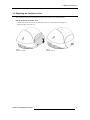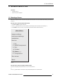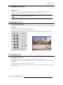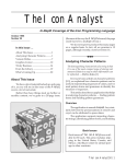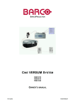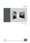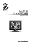
1
Copyright ©
All rights reserved. No part of this document may be copied, reproduced or translated. It shall not otherwise be recorded, transmitted or stored
in a retrieval system without the prior written consent of BARCO.
Changes
Barco provides this manual ’as is’ without warranty of any kind, either expressed or implied, including but not limited to the implied warranties
of merchantability and fitness for a particular purpose. Barco may make improvements and/or changes to the product(s) and/or the program(s) described in this publication at any time without notice.
This publication could contain technical inaccuracies or typographical errors. Changes are periodically made to the information in this publication; these changes are incorporated in new editions of this publication.
Trademarks
Brand and product names mentioned in this manual may be trademarks, registered trademarks or copyrights of their respective holders. All
brand and product names mentioned in this manual serve as comments or examples and are not to be understood as advertising for the
products or their manufactures.
Federal Communication Commission (FCC Statement)
This equipment has been tested and found to comply with the limits for a Class B digital device, pursuant to Part 15 of the FCC Rules. These
limits are designed to provide reasonable protection against harmful interference when the equipment is operated in a residential environment. This equipment generates, uses, and can radiate radio frequency energy and, if not installed and used in accordance with the
instruction manual, may cause harmful interference to radio communications. Operation of this equipment in a residential area is likely to
cause harmful interference in which case the user is encouraged to try to correct the interference by one or more of the following measures.
Introduction to the user:
If this equipment does cause interference to radio or television reception, the user may try to correct the interference by one or more of the
following measures:
•
Re-orientation of the receiving antenna for the radio or television.
•
Relocate the equipment with respect to the receiver.
•
Plug the equipment into a different outlet so that the equipment and receiver are on different branch circuits.
•
Fasten cables connectors to the equipment by mounting screws.
The use of shielded cables is required within the limits of Part 15 of FCC rules and EN55022.
Guarantee and Compensation
Barco provides a guarantee relating to perfect manufacturing as part of the legally stipulated terms of guarantee. On receipt, the purchaser
must immediately inspect all delivered goods for damage incurred during transport, as well as for material and manufacturing faults. Barco
must be informed immediately in writing of any complaints.
The period of guarantee begins on the date of transfer of risks, in the case of special systems and software on the date of commissioning, at
latest 30 days after the transfer of risks. In the event of justified notice of complaint, Barco can repair the fault or provide a replacement at its
own discretion within an appropriate period. If this measure proves to be impossible or unsuccessful, the purchaser can demand a reduction
in the purchase price or cancellation of the contract. All other claims, in particular those relating to compensation for direct or indirect damage,
and also damage attributed to the operation of software as well as to other services provided by Barco, being a component of the system or
independent service, will be deemed invalid provided the damage is not proven to be attributed to the absence of properties guaranteed in
writing or due to the intent or gross negligence or part of Barco.
If the purchaser or a third party carries out modifications or repairs on goods delivered by Barco, or if the goods are handled incorrectly, in
particular if the systems are commissioned operated incorrectly or if, after the transfer of risks, the goods are subject to influences not agreed
upon in the contract, all guarantee claims of the purchaser will be rendered invalid. Not included in the guarantee coverage are system failures which are attributed to programs or special electronic circuitry provided by the purchaser, e.g. interfaces. Normal wear as well as normal
maintenance are not subject to the guarantee provided by Barco either.
The environmental conditions as well as the servicing and maintenance regulations specified in this manual must be complied with by the
customer.
Table of contents
TABLE OF CONTENTS
1.
SAFETY INSTRUCTIONS..........................................................................................................3
1.1
1.2
2.
OVERVIEW OF USER’S CONTROLS .......................................................................................5
2.1
2.2
2.3
3.
Selecting a Source..................................................................................................................................................................15
Menu-to-connector Comparison..............................................................................................................................................16
IMAGE CONTROL....................................................................................................................17
6.1
6.2
6.3
6.4
6.5
6.6
7.
Switching on the Projector ......................................................................................................................................................13
Switching between STANDBY and OPERATION....................................................................................................................13
Switching off the Projector ......................................................................................................................................................13
SOURCE SELECTION .............................................................................................................15
5.1
5.2
6.
Removing the Connector Cover ................................................................................................................................................9
Connecting Input Devices .........................................................................................................................................................9
Replacing the Connector Cover ..............................................................................................................................................11
SWITCHING ON/OFF THE PROJECTOR ...............................................................................13
4.1
4.2
4.3
5.
Projector ...................................................................................................................................................................................5
Remote Control.........................................................................................................................................................................5
Remote Control Operation ........................................................................................................................................................7
2.3.1
General .......................................................................................................................................................................7
2.3.2
Battery Insertion in the Remote Control ......................................................................................................................8
MAKING CONNECTIONS ..........................................................................................................9
3.1
3.2
3.3
4.
General Safety Instructions.......................................................................................................................................................3
Projector Related Safety Information ........................................................................................................................................3
Brightness Control ..................................................................................................................................................................17
Contrast Control......................................................................................................................................................................17
Sharpness (Detail) Control......................................................................................................................................................18
Color (Saturation) Control .......................................................................................................................................................18
Tint Control .............................................................................................................................................................................19
Aspect Ratio Control ...............................................................................................................................................................19
PICTURE IN PICTURE .............................................................................................................21
7.1
7.2
7.3
7.4
7.5
Brief Introduction.....................................................................................................................................................................21
Turning On/Off PIP .................................................................................................................................................................21
Selecting the PIP Source ........................................................................................................................................................22
Configuring the PIP Window ...................................................................................................................................................22
Remote Control PIP Configuration ..........................................................................................................................................23
R5976691 CINE VERSUM 70/60 12042004
1
Table of contents
2
R5976691 CINE VERSUM 70/60 12042004
1. Safety Instructions
1. SAFETY INSTRUCTIONS
Overview
•
General Safety Instructions
•
Projector Related Safety Instructions
This manual is intended for the user/operator of the installed projector. Any change in cabling or servicing of the
installed projector must be performed by service personnel having appropriate technical training and experience
necessary to be knowledgeable of potential hazards to which they are exposed in performing a task, and of
measures to minimize the potential risk to themselves or other persons.
1.1 General Safety Instructions
Lightning
For added protection for this projector during a lightning storm, or when it is left unattended and unused for long periods of time, unplug
it from the wall outlet and disconnect the power cord. This will prevent damage to the projector due to lightning and power-line surges.
Object and liquid entry
Never push objects of any kind into the modules through openings as they may touch dangerous voltage points or short-out parts that
could result in a fire or electrical shock. Never spill liquid of any kind on the product.
Servicing
Do not attempt to service the modules yourself as opening or removing covers may expose you to dangerous voltage or other hazards.
Refer all servicing to qualified service personnel.
Damage requiring servicing
Unplug the modules from the wall outlet and refer servicing to qualified service personnel under the following circumstances:
•
If the power-supply cord or plug is damaged.
•
If liquid has been spilled, or objects have fallen into the projector.
•
If the projector has been exposed to rain or water.
•
If the product exhibits a distinct change in performance, this indicates a need for service.
1.2 Projector Related Safety Information
On cooling
The cooling fans in this projector continue to run for about 1 min. after the projector is turned off. During normal operation, when turning the power off always use the power down function on the remote control. Ensure the cooling fans have stopped before switching off
the projector using the power switch.
DURING NORMAL OPERATION, NEVER TURN THE PROJECTOR OFF BY DISCONNECTING THE POWER CORD. FAILURE TO
OBSERVE THIS WILL RESULT IN PREMATURE LAMP FAILURE.
Slots and openings
Slots and openings in the cabinet and the sides are provided for ventilation; to ensure reliable operation of the projector and to protect
it from overheating, these openings must not be blocked or covered.
Image 1-1
Air inlet/outlets
R5976691 CINE VERSUM 70/60 12042004
3
1. Safety Instructions
Protection from ultraviolet radiation
WARNING: DO NOT LOOK DIRECTLY IN THE HIGH INTENSITY LIGHT BEAM. The lamp contained in this product is an intense
source of light and heat. One component of the light emitted from the lamp is ultraviolet light.
4
R5976691 CINE VERSUM 70/60 12042004
2. Overview of User’s Controls
2. OVERVIEW OF USER’S CONTROLS
Overview
•
Projector
•
Remote Control
•
Remote Control Operation
2.1 Projector
Top view
The top side of the projector is provided with the following controls:
1
2
3
4
Image 2-1
Projector controls
Controls function description
Ref.
Function
Description
1
Infrared receiver
Infrared reception diode for the IR signals from the IR transmitter.
Allows switching On/Off (Standby) of the projector.
2
Infrared reception LED indicator
Lights up when a valid IR signal from the remote control has been
captured.
3
Standby LED
Lights up continuously: projector in operation mode.
Lights up repeatedly 2 times short, 1 time long, off: projector in
standby mode.
Blinks fast: projector in cooling down mode after switching off (duration 1 min.).
Lights up repeatedly 1 time long, 1 time short, off: projector has been
started up in cooling down mode, waiting for lamp ignition.
4
Main power switch
Button pressed, switches the projector in ’standby’ mode. This mode
is indicated by the standby LED which lights up repeatedly 2 times
short, 1 time long, off.
Table 2-1
2.2 Remote Control
Top side
The Infrared remote control buttons support the following functionality:
Buttons that are not labeled in the following remote control illustration have no function.
R5976691 CINE VERSUM 70/60 12042004
5
2. Overview of User’s Controls
Image 2-2
Remote control
Ref.
Function
Description
1
Remote control operation indication
Lights up when a button on the remote control is pressed (Visual indication of remote control operation – Battery check).
2
F1-5 buttons
Activate PIP functions. See “Picture in Picture” on page 21.
3
ADJ (Adjust button)
Toggle button to enter or exit the adjustment mode.
4
System setting
Service function only.
5
PAUSE
Press to stop the image projection, press again to restart.
6
Standby button
To power up/down the projector.
7
Digit buttons
Allow direct input selection in system setting.
8
Picture controls
Allow optimization of picture reproduction.
9
Aspect ratio button
Press to scroll through aspect ratio (width-to-height) settings of projected
image.
10
FREEZE
Press to freeze the image.
11
TEXT
Press to remove bar scale display when adjusting picture. (Handy when
adjusting picture during a meeting.) Press button again for re-activation.
12
ENTER
Press to start the adjustment mode, confirm an adjustment or selection
in the adjustment mode. Press again to leave the adjustment mode.
13
Cursor buttons
Allow menu selections in the adjustment mode.
14
EXIT
Press to leave the adjustment mode via scrolling upwards in the menu structure.
Table 2-2
6
R5976691 CINE VERSUM 70/60 12042004
2. Overview of User’s Controls
2.3 Remote Control Operation
Overview
•
General
•
Battery Insertion in the Remote Control
2.3.1
General
How to use
This remote control includes a battery powered infrared transmitter which allows the user to control the projector remotely via its own
built-in infrared receiver.
When operating the remote control unit, point it at any of the remote sensors, located on the front, front top, and rear of the projector.
The remote control unit is operable up to 9 meters from the unit and within a 45-degree angle on each side of the sensor (image 2-3).
The signal from the remote control can be reflected off a screen for easy operation. However, the effective distance of the signal may
differ due to the screen material.
+
VOL
-
CE
+
BALAN
BASS
-
+
+
R
CONT
-
-
+
LE
+
TN
BRIGH
TREB
-
-
2
R
+
COLO
1
-
4
+
TINT
3
-
6
5
+
SHAR
PN
-
8
7
E
+
PHAS
-
0
R
TEXT
9
ENTE
?
E
PAUS
EXIT
F5
F4
F3
ADJ
F2
F1
45 45
F3
F2
F4
F5
F1
EXIT
ADJ
ENTER
TEXT
PAUSE
-
?
-
-
SHARPN
+
TINT
+
F2
-
6
J
AD
0
8
5
F1
9
7
+
PHASE
F3
+
+
F5
BRIGHTN
CONTR
IT
EX
SE
PAU
?
-
9
2
1
F4
-
4
3
+
COLOR
T
TEX
0
-
+
+
T
TIN
-
+
-
+
TR
CON
+
S
BAS
N
GHT
BRI
+
+
-
BLE
-
TRE
LOR
CO
2
-
VOL
RPN
SHA
-
4
BASS
+
SE
PHA
+
6
+
BALANCE
8
-
1
+
3
TREBLE
-
ER
ENT
7
5
-
-
+
-
NCE
BALA
+
VOL
+
Image 2-3
Remote control operating range
Backlighting
When a button on the remote control is pressed, backlight is activated automatically. That allows the user to operate the remote control
in a dark room. Backlight is turned off automatically a few seconds after the last key activation.
If the backlight and remote control operation indicator light up too long or continuously, the batteries need to be
replaced.
R5976691 CINE VERSUM 70/60 12042004
7
2. Overview of User’s Controls
2.3.2
Battery Insertion in the Remote Control
Where to find the batteries
The batteries are not placed in the remote control to avoid remote control operation in its package, resulting in a shorter battery life
time.
How to install the batteries
1. Push the cover tab (A) with the fingernail a little backwards and pull upwards the cover top (B). (Image 2-4)
2. Lift the cover forwards to remove (image 2-5).
3. Push the battery body towards the spring and lift it up to remove (image 2-6).
4. Insert two AA size batteries, making sure the polarities match the + and – marks inside the battery compartment (image 2-6).
5. Insert the lower tab of the battery cover in the gap at the bottom of the remote control, and press the cover until it clicks in place
(image 2-6).
Image 2-4
Battery cover unlock
Image 2-5
Battery cover removal
Image 2-6
Battery replacement
8
R5976691 CINE VERSUM 70/60 12042004
3. Making Connections
3. MAKING CONNECTIONS
Overview
•
Removing the Connector Cover
•
Connecting Input Devices
•
Replacing the Connector Cover
3.1 Removing the Connector Cover
Before you can connect the power cord and input devices to the projector, the connector cover must be removed.
How to remove the connector cover
1. Loosen the captive screw (image 3-1).
2. Lift up at the bottom firmly and “snap” the cover loose (image 3-2).
The cover makes a loud “snap” when removed: this is normal and does not damage the cover.
Image 3-1
Connector cover unlock
Image 3-2
Connector cover removal
3.2 Connecting Input Devices
Various video devices and a PC or notebook computer can be connected to the projector at the same time. Video devices include
DVD, VCD, and VHS players, as well as movie camcorders and digital still cameras. Check the user manual of the connecting device
to confirm it has the appropriate output connector.
Component versus composite video
In component video the term component describes a number of elements that are needed to make up the video
picture; these components are PR/Y/PB. A composite video signal on the other hand contains all the information
needed for the color picture in a single channel of information.
R5976691 CINE VERSUM 70/60 12042004
9
3. Making Connections
Connector View
Image 3-3
Connectors and power plug
Ref.
Function
Description
1
S-video
Connect an S-video cable from the S-video out connector on the video
device to this connector.
2
Video (composite)
Connect a composite video cable from the video (composite) out connector on the video device to this connector.
3
RGBHV (5-cable)
RGSB (sync on green)
RGBS (SCART)
Connect a 5-cable RGB cable from the video (component) out connectors on the video device to these connectors.
PrYPb
4
PrYPb (component)
Connect an RGB cable from the video (component) out connectors on
the video device to these connectors.
5
VGA input
Connect a VGA (analog) cable from a computer to this connector.
6
Power
Connect the female connector of the supplied power cable to this connector. Connect the other end to an electrical outlet only after you have
finished all other connections and replaced the connector cover.
7
DVI input
Connect a DVI (digital) cable from a computer or video source to this
connector.
8
RS232/RS422 in
This is a service port for firmware upgrades or RS232 control of the
projector.
9
Screen
Connect a 12-volt trigger cable from the screen to this connector. When
connected, the screen automatically adjusts vertically to match the
screen aspect ratio.
10
Aspect ratio
Connect a 12-volt trigger cable from the screen to this connector. When
connected, the screen automatically adjusts horizontally to match the
screen aspect ratio.
Table 3-1
Aspect ratio
The screen aspect ratio is the ratio of width to height. The aspect ratio of a standard TV set is 4:3. The highdefinition TV (HDTV) format is 16:9. The projector’s screen and aspect ratio feature automatically adjusts the
screen size to match the output ratio from the projector.
10
R5976691 CINE VERSUM 70/60 12042004
3. Making Connections
3.3 Replacing the Connector Cover
After connecting the power cord and input devices to the projector, the connector cover should be replaced.
How to replace the connector cover
1. Insert the cover brackets first, and then push down firmly until the cover “snaps” back into place (image 3-4).
2. Tighten the captive screw (image 3-5).
Image 3-4
Connector cover replace
R5976691 CINE VERSUM 70/60 12042004
Image 3-5
Connector cover lock
11
3. Making Connections
12
R5976691 CINE VERSUM 70/60 12042004
4. Switching ON/OFF the Projector
4. SWITCHING ON/OFF THE PROJECTOR
Overview
•
Switching on the Projector
•
Switching between STANDBY and OPERATION
•
Switching off the Projector
4.1 Switching on the Projector
How to switch on
Press the main power switch on the projector.
The projector goes from OFF to STANDBY, visualized by blinking of the standby LED.
4.2 Switching between STANDBY and OPERATION
How to switch between STANDBY and OPERATION
Press the Standby button on the remote control to switch the projector to OPERATION.
4.3 Switching off the Projector
How to switch off
1. Press the Standby button on the remote control for 2 seconds. The projector turns off automatically after 1 minute.
2. Press the power switch on the projector.
3. Let the projector cool down for at least 15 minutes.
R5976691 CINE VERSUM 70/60 12042004
13
4. Switching ON/OFF the Projector
14
R5976691 CINE VERSUM 70/60 12042004
5. Source Selection
5. SOURCE SELECTION
Overview
•
Selecting a Source
•
Menu-to-connector Comparison
5.1 Selecting a Source
More than one input device can be connected to the projector at the same time. The source selection menu allows you to select the input source.
How to select a source from the main menu
1. Press ADJ or ENTER to open the main menu.
2. Press ↑ or ↓ (up/down buttons on the remote control) to scroll through the menu and select a source (image 5-1).
3. Press ENTER to confirm your choice. (The system may take several seconds to detect the source.)
Main Menu
Image settings
Advanced settings
Installation
Service
1. PC
2. RGB/Component
3. DVI
4. SVideo
*5. Video
6. Component
Shut down
Back
Image 5-1
Main menu
How to select a source using the remote control
Press the corresponding number for the source 1 to 6 on the remote control.
or
Press ↑ or ↓ (up/down buttons on the remote control) to automatically search for connected devices.
R5976691 CINE VERSUM 70/60 12042004
15
5. Source Selection
5.2 Menu-to-connector Comparison
The input source that you select from the main menu corresponds directly to one of the connectors on the projector, and to the input
device connected to that connector (image 5-2).
4
5
Main Menu
Image settings
Advanced settings
Installation
PC INPUT
2
Service
6
1. PC
2. RGB/Component
3. DVI
1
4. SVideo
*5. Video
6. Component
Shut down
Back
3
Image 5-2
Menu-to-connector comparison
16
R5976691 CINE VERSUM 70/60 12042004
6. Image Control
6. IMAGE CONTROL
Image controls
The Brightness, Contrast, Sharpness (Detail), Color and Tint (Hue) functions are accessed directly from the remote control.
The adjustment functions, when selected, display a slide bar overlayed on the source image (only if text is On).
It is useful to adjust the Brightness whenever the ambient room lighting changes. The same is true for Contrast.
For best results, change the Brightness, then the Contrast.
6.1 Brightness Control
How to adjust the Brightness
The Brightness function is used to adjust the overall light output. To adjust the Brightness, press the (-) or (+) side of the ’BRIGHTN’
button (image 6-1).
The following barscale is overlayed on the source image (image 6-2).
Press the (+) button for a brighter image or the (-) button for a darker image.
If video or data is displayed with a black background, adjust until the background just appears (black becomes a very dark grey).
Image 6-1
Image 6-2
6.2 Contrast Control
How to adjust the Contrast
The Contrast function is used to adjust the contrast between the light and dark areas of the displayed image.
To adjust Contrast, press the (-) or (+) side of the ’CONTR’ button (image 6-3). The following barscale is overlayed on the source image (image 6-4).
Press the (+) or (-) button until dark parts of the image show good detail.
If Contrast is set too light, the image loses detail and clarity. If set too low, it may be difficult to distinguish between foreground and
background information.
R5976691 CINE VERSUM 70/60 12042004
17
6. Image Control
Image 6-3
Image 6-4
6.3 Sharpness (Detail) Control
How to adjust the Sharpness
The Sharpness function is used to adjust the image sharpness of video signals when using a video decoder installed in the projector.
To adjust the Sharpness, press the (-) or (+) side of the ’SHARPN’ button (image 6-5). The following barscale is overlayed on the
source image (image 6-6).
Press the (+) or (-) button until the sharpest display is attained. Detail level should be roughly proportional to the input signal quality.
Higher levels of detail improve good quality levels. Low levels of detail reduce noise in poor quality signals.
Image 6-5
Image 6-6
6.4 Color (Saturation) Control
How to adjust the Color (saturation)
The Color function is used to adjust color saturation levels and is only active for Video and S-Video sources.
To adjust Color, press the (-) or (+) side of the ’COLOR’ button (image 6-7). The following barscale is overlayed on the source image
(image 6-8).
Press the (+) or (-) button until the desired color saturation level is displayed. If the color is set to a 0% level, the result will be black
and white picture. If the color is set too high, the color levels in the image will be over-powering.
18
R5976691 CINE VERSUM 70/60 12042004
6. Image Control
Image 6-7
Image 6-8
6.5 Tint Control
How to adjust the Tint (hue)
The Tint function is used to adjust color hue to obtain true color reproduction and is only active for Video and S-Video when using the
NTSC 4.43 or NTSC 3.58 color system.
To adjust Tint, press the (-) or (+) side of the ’TINT’ button (image 6-9). The following barscale is overlayed on the source image
(image 6-10).
Press the (+) or (-) button until an optimal display is obtained. It is best to adjust tint while displaying an image with natural flesh tones.
Image 6-9
Image 6-10
6.6 Aspect Ratio Control
How to adjust the Aspect Ratio
This function allows you to modify or customize the image display mode to enhance the input image.
1. Press * on the remote control (image 6-11) to open the Aspect ratio menu.
The Aspect ratio menu appears on the screen including all available aspect ratios (image 6-12).
R5976691 CINE VERSUM 70/60 12042004
19
6. Image Control
Explanation
Aspect Ratio
Description
16:9
Wide screen television format/Anamorphic format.
4:3
Standard television format (no effect in 1080i digital TV).
5:4
Workstations format (no effect in 1080i digital TV).
2.35:1
Panavision or Cinemascope format, frequently used by Hollywood films.
1.78:1
Wide screen television format/Anamorphic format.
Letterbox
Forces the letter format of the input signal into the native panel resolution.
2. Press * to scroll through the available options.
3. Press ENTER to confirm your selection.
Image of the input signal is displayed in the selected format.
Image 6-11
Image 6-12
Image 6-13
A Letterbox format input signal
B Conversion to native panel resolution
20
R5976691 CINE VERSUM 70/60 12042004
7. Picture In Picture
7. PICTURE IN PICTURE
Overview
•
Brief Introduction
•
Turning PIP On/Off
•
Selecting the PIP Source
•
Configuring the PIP Window
•
Remote Control PIP Configuration
7.1 Brief Introduction
If PIP is enabled, a window is inserted in the active image, in which the image of another selected input source will be displayed. The
position and the size of the window are adjustable.
PIP (Picture In Picture) mode allows you to view a small video window in a full-screen video display. For example,
while displaying output from your PC you could have a small window displaying your video source.
7.2 Turning On/Off PIP
How to turn On/Off PIP
1. Press ADJ to open the Main menu.
The Main menu appears on the screen (image 7-1).
2. Press ↑ or ↓ to select Advanced settings and press ENTER.
The Advanced settings menu appears on the screen (image 7-2).
3. Press ↑ or ↓ to select PIP configuration and press ENTER.
The PIP configuration menu appears on the screen (image 7-3).
4. Press ↑ or ↓ to select PIP.
5. Press ENTER to turn PIP on or off.
Main Menu
Image settings
Advanced settings
Installation
Service
* 1. PC
2. RGB/Component
3. DVI
Advanced settings
Aspect Ratio
PIP configuration
Position
Pip
PIP configuration
Horizontal shift
5. Video
Blanking
Vertical shift
6. Component
Input Balance
Window size
4. SVideo
PIP source
On
Video
Shut down
Back
Image 7-1
R5976691 CINE VERSUM 70/60 12042004
Back
Image 7-2
Back
Image 7-3
21
7. Picture In Picture
7.3 Selecting the PIP Source
The main screen and PIP screen are automatically selected from connected devices.
The main screen
When a PC is present on connectors 1 (PC) or 3 (DVI) on the projector, it displays by default as the main (full-screen) picture. The device on connector 3 (DVI) only displays when no device is present on connector 1 (PC).
The PIP screen
When a video device is present on connectors 4 (SVideo) or 5 (Video) on the projector, it displays by default as the PIP picture. The
device on connector 5 (Video) only displays when no device is present on connector 4 (SVideo).
PIP
source (1)
4
PIP
source (2)
5
Main Menu
Image settings
Advanced settings
Installation
Service
PC INPUT
1. PC
Main
source (1)
1
2. RGB/Component
3. DVI
4. SVideo
*5. Video
6. Component
Shut down
Back
Main
3 source (2)
Image 7-4
Main screen and PIP screen source
7.4 Configuring the PIP Window
How to adjust the horizontal position
1. Select the PIP configuration menu. (Turning On/Off PIP, page 21.)
2. Press ↑ or ↓ to select Horizontal shift and press ENTER.
3. Press ← or → to move the PIP window horizontally on the main screen (image 7-5).
Image 7-5
22
R5976691 CINE VERSUM 70/60 12042004
7. Picture In Picture
How to adjust the vertical position
1. Select the PIP configuration menu. (Turning On/Off PIP, page 21.)
2. Press ↑ or ↓ to select Vertical shift and press ENTER.
3. Press ← or → to move the PIP window vertically on the main screen (image 7-6).
Image 7-6
How to adjust the window size
1. Select the PIP configuration menu. (Turning On/Off PIP, page 21.)
2. Press ↑ or ↓ to select Window size and press ENTER.
3. Press ← or → to increase/decrease the size of the PIP window (image 7-7).
Image 7-7
7.5 Remote Control PIP Configuration
Dedicated buttons on the remote control allow you to quickly configure the PIP window (image 7-8).
Button
Description
F1
Move PIP window to upper-left corner of screen
F2
Move PIP window to bottom-left corner of screen
F3
Switch PIP source and main source
F4
Move PIP window to bottom-right corner of screen
F5
Move PIP window to upper-right corner of screen
Table 7-1
Image 7-8
R5976691 CINE VERSUM 70/60 12042004
23
7. Picture In Picture
24
R5976691 CINE VERSUM 70/60 12042004